|
CptAJ posted:Quick couple of questions here. First of all, I don't really know much about electronics but I can't stop myself from breaking stuff open. That said, I was recently playing a mighty fine game of CIV4 and my computer crashed horribly. Seeing as the screen went to poo poo and I knew the videocard's fan was busted, I figured it was overheating. I decided to remove the fan and play mcguyver by putting a casefan pointing towards it. Thats when I noticed 3 bloated caps. Some of them have already started oxidizing or whatever. Yeah, they should work. Just be aware that you would probably be putting your card out of warranty by replacing components on it...
|
 #
?
Mar 29, 2009 00:34
#
?
Mar 29, 2009 00:34
|
|


|

|
| # ? Jun 3, 2024 22:27 |
|
|
It worked. I rock. You guys rock. We all rock. =) *Goes back to playing CIV4*
|
|
#
?
Mar 29, 2009 03:30
|
|
|
Mill Town posted:Put a few kHz or so square wave out the LEDs and a high-pass filter on the detector? Coincidentally I was just looking at a Panasonic PNA4602M, a sensor that detects only IR light at around 38kHz. You can get it for only a couple dollars on Digikey, it's tiny, and it doesn't need any extra equipment. If you have a spare PWM output or space for a 555 timer you'll be good to go.
|
|
#
?
Mar 29, 2009 06:39
|
|

|
TwoShanks posted:I am currently building several robots which are attracted to light and have ultrasonic collision sensing. I'm now trying to think of a way to make the robots able to find and move toward each other in certain circumstances. I was going to use infrared emitters and detectors but the lights produce too much IR and overwhelm the LEDs. That sounds like a fun project ") Just a word of caution to you - even though you can't hear ultrasonic frequencies, they're still dangerous to your hearing. Maybe moreso because you can't percieve how loud they are. I work with a guy who is mostly deaf. He blames it on a few years of working with 40kHz transducers and not paying attention to their directivity or volume.
|
|
#
?
Mar 29, 2009 09:37
|
|

|
The ultrasonics on the robot are quite low-level - I'm only using them to detect objects closer than about 5cm or so. I'll keep it in mind though, my previous project was an ultrasonic distance measurement system with about 15m range. The robot project has been fun so far, much more complicated than anything else I've built. It has about 15 randomly-generated variables such as speed, turning circle, sensitivity to light, etc. It also has an "energy" value which counts down at different rates depending on the speed variable and goes up when the light is above a certain value. The robot "dies" when the energy runs out. The next step in the project is to have a "breeding" energy threshold where the robots will be attracted to the dead units and transmit their variables across with a slight chance of mutation. The dead unit then starts up with the new variables. I'm planning to build a lot of the little things and let them "evolve" in different conditions to see what happens to the variables - it should be interesting.
|
|
#
?
Mar 29, 2009 12:42
|
|
|
Working on a big project. Involving two AT91SAM7s plus an ATmega8. There's going to be a motherboard with a SAM7 and a bluetooth module, a SAM7 comms board with a CMOS camera and an infra-red system, and an ATmega8 motor control/peripheral board. What is the best way to detect IR signals from a TV remote or similar? It will have to compete with a bunch of other similar robots. Can I just use a biasing network for an IR detecting diode, interface it in GPIO, and do everything in software? Are there commonly available IR systems that operate on a different wavelength to standard TV ones, and would be immune to the effects of them?
|
|
#
?
Mar 29, 2009 23:02
|
|
|
catbread.jpg posted:What is the best way to detect IR signals from a TV remote or similar? It will have to compete with a bunch of other similar robots. Can I just use a biasing network for an IR detecting diode, interface it in GPIO, and do everything in software? This is similar to the problem I was having (thanks BattleMaster!). From recent reading, TV remotes use a carrier frequency usually around 38kHz. Various sensors are available that will only detect IR at specific frequencies - I've found them available from 30-40kHz. They are single sensors with integrated amplification, no external circuitry needed. I've just ordered a bunch of OSRAM SFH 5110-36 sensors for this purpose.
|
|
#
?
Mar 29, 2009 23:36
|
|
|
TwoShanks posted:This is similar to the problem I was having (thanks BattleMaster!). From recent reading, TV remotes use a carrier frequency usually around 38kHz. Various sensors are available that will only detect IR at specific frequencies - I've found them available from 30-40kHz. They are single sensors with integrated amplification, no external circuitry needed. Those look pretty good. Now I just have to figure out how to find/modify an IR remote to have a non-standard carrier frequency.
|
|
#
?
Mar 29, 2009 23:46
|
|
|
Hurf durf magnetic compass nevermind.
|
|
#
?
Mar 30, 2009 03:10
|
|


|
catbread.jpg posted:Working on a big project. Involving two AT91SAM7s plus an ATmega8. And by the way, IR transistors and diodes normally have considerable capacitance, meaning using them at high frequencies isn't always easy. For instance, when using an IR transistor in a normal common emitter configuration, its bandwidth might only be 5KHz. Getting it above that requires some analog tricks; most likely cascoding. How much data bandwidth are you trying to encode? Any idea what modulation scheme you'll use? Is directionality an issue?
|
|
#
?
Mar 31, 2009 14:11
|
|


|
My power amp has a 12v auto turn on feature to it. It is hooked up through a 4 screwed terminal block, two brass two black(I believe it is a passthrough). It was designed to be used in conjuction with the preamp but I talked to the manufacturer and got this information from them.quote:I would recommend using something that provides 100ma up to 1amp. The amp is currently hooked up to my HTPC and I was wondering if I could use one of the 4 pin molex connectors, using yellow and black, off the psu to hook it up.
|
|
#
?
Mar 31, 2009 18:29
|
|
|
ANIME AKBAR posted:I supposed you could do a lot of it in software, but a simple analog bandpass filter and demodulator would probably be easier, unless you're much more comfortable with the software side of things. I'll be looking at the OSRAM SFH 5110-36 mentioned, which does all of the above already. The idea here is to use standard equipment (TV remote or similar, hopefully one encoded RC-5), but perhaps modified to use a different carrier frequency. Not sending lots of data, I'll end up training it to use the arbitrary signals of the TV remote.
|
|
#
?
Mar 31, 2009 20:23
|
|
|
I've never worked with RC-5, but after some reading I would suggest the following approach: If you have an IR receiver that's got built-in carrier removal, you could save yourself some trouble here and skip right to the decoding phase. Otherwise, you can assume you're going to get a ~40kHz carrier wave out of the IR receiver. In this case, I'd take the square-wave output of your IR receiver and run it through an analog lowpass filter (even a passive RC would be fine). Since the worst-case frequency content of your signal is 1/32 of the carrier frequency, you could filter the carrier right out with even a first-order lowpass filter and still leave the band of interest pretty much untouched. Run the output through a comparator and you've got the manchester-encoded data stream, carrier-free. The question from here is what to do with it. If you have an RTOS or something, you might be able to do all the sampling and decoding in software. Otherwise I'd either buy a chip designed for de-encoding and de-serializing your data or else use a CPLD and make my own. EDIT: Another approach that might be interesting would be to use 9600 baud for your manchester transition rate (which would work out to 4800 bits per second), and then running the comparator output directly into your micro's UART. You'd have to work out the mapping function between a "byte" of manchester and a nibble of actual data, but that would be pretty reasonable to do. Poopernickel fucked around with this message at 03:35 on Apr 1, 2009 |
|
#
?
Apr 1, 2009 03:29
|
|
|
Poopernickel posted:I've never worked with RC-5, but after some reading I would suggest the following approach: If I use the component above, that's all taken care of, I'm left with a serial data stream. I want to use a stock *transmitter*. Not too worried about decoding the serial data.
|
|
#
?
Apr 1, 2009 07:54
|
|
|
Oh, my bad - If that's the case, you can probably do the transmitting from within software (assuming you don't have any critical tasks which need to occur at the same time). It would be pretty straightforward to send serial manchester data out of your micro. You could do it either by bit-banging, by using the UART port, or by using a peripheral of some sort (CPLD or maybe a serializer chip). I'd avoid trying to bang out a 40kHz square wave, because that begins to approach frequencies where you will have to count and conserve your clock cycles. Instead, I'd recommend using an oscillator of your desired carrier frequency (you can buy pre-programmed oscillator chips or build a crystal circuit) and a generic discrete AND gate, with one input tied to the oscillator and the other input tied to an inverted copy of your manchester stream (or just generate it upside-down).
|
|
#
?
Apr 1, 2009 09:18
|
|
|
Can I get some advice on my H-bridge? I want to build a dual H-bridge motor controller for my RC crawler. The H-bridges would be controlled by some kind of atmel chip, perhaps an ATTiny. The bridge will be running at a pwm frequency of say 3000hz. For the sake of safety I have tried to make it impossible to short circuit the bridge by having a bridge off pin (V4) and a pwm control pin (V3). The battery voltage is 8.4v (V1) and the mosfets IRF3415 because I have a bunch of them. These are n-channel, so a voltage doubler chip is used to make the V2 voltage which is needed to run the gates of the top mosfets. I have tried to make this as simple as possible, but although this design appears to work in simulation it makes very inefficient use of V2. The doubler chip can only supply 80mA, and I am burning it all away by sinking the mosfet gates to ground. R1 and R3 can't be increased because the mosfets have a rather high gate charge (200nC). 
|
|
#
?
Apr 1, 2009 17:34
|
|

|
Why not just use a dual H-bridge IC?
|
|
#
?
Apr 1, 2009 18:01
|
|
|
I built a discrete class-D amplifier a couple of years back, and I used basically the same setup you've got (except mine was a half-bridge) and I used complementary mosfets. What my experience taught me is that it's easier and often cheaper to buy it inside of a chip instead. Depending on your interest, you can either buy chips that have the whole H-bridge and drivers inside of it, or you can buy dedicated gate drive chips (I recommend these) which accept a logic-level input and provide gate signals suitable for a power MOSFET. Check out Linear Technology's and International Rectifier's various offerings. As far as feedback on your design goes, it seems to be missing the bootstrap circuits you typically see driving the high-side NMOS's gates. These are normally needed because you have to bias [V(g)-V(s)] and V(s) is connected to your load rather than to something with a constant voltage. This might be why you've having such a tough time running your design without using those monster pullup resistors. If you want to do the design yourself, consider using a bootstrap approac for the high-side or switching to complementary NMOS and PMOS instead. The January issue of Nuts and Volts had a pretty interesting article all about this subject. Poopernickel fucked around with this message at 18:33 on Apr 1, 2009 |
|
#
?
Apr 1, 2009 18:20
|
|
|
BattleMaster posted:Why not just use a dual H-bridge IC? Haven't really found any of these (or single ones for that matter) that put out the currents/voltages I'd like to use. The crawler doesn't need very much (8.4V 6A per motor) but I kinda wanted to have a scalable design for future projects such as CNC servos. Poopernickel posted:dedicated gate drive chips (I recommend these) Sounds interesting. I'll have a look around. As for the bootstraps you mentioned, that's something I didn't even consider, need to absorb some more knowledge I guess..
|
|
#
?
Apr 1, 2009 18:40
|
|
|
Astrolite posted:Haven't really found any of these (or single ones for that matter) that put out the currents/voltages I'd like to use. The crawler doesn't need very much (8.4V 6A per motor) but I kinda wanted to have a scalable design for future projects such as CNC servos. Oh, when you said "RC crawler" I was envisioning something much, much smaller. What are you using to power that thing, a car battery?!
|
|
#
?
Apr 1, 2009 18:58
|
|
|
BattleMaster posted:Oh, when you said "RC crawler" I was envisioning something much, much smaller. What are you using to power that thing, a car battery?! Haha, while 6A is admittedly the peak current draw this thing still drains batteries like nothing else. It's got a 2cell (~8V) 9400mAh lipo pack in it. By the way, I've got another rc car with a mamba max brushless system, which apparently can draw upwards of 80 amps peak. There's some zesty mosfets in that one for sure.
|
|
#
?
Apr 1, 2009 19:22
|
|
|
Well, it kinda worked. Turns out the problem persists. Oh well, at least I discovered I can effectively change caps and those needed replacing anyway (I'm surprised they didn't fail before since they were leaking and whatnot). I wan't to try testing the rest of the caps on the card, see if they're alright (Hopefully thats the problem since I can hardly change anything else in there) Anyway, here's the cheapo tester I have. Can it test capacitors? Actually, do any of you mind giving me a crash course explanation on what each of those functions do? Learning never hurt nobody... unless maybe Marie Curie or something I guess 
|
|
#
?
Apr 2, 2009 01:00
|
|
|
Sorry, your meter won't work for testing caps. The left green region is for measuring resistance. The left white region is for measuring DC voltage. The right white region is for measuring AC voltage. The right green region is for measuring DC current. Your meter can also test diodes and transistors, but I doubt you'd have a use for that.
|
|
#
?
Apr 2, 2009 01:52
|
|

|
Thanks. Its good to know what the thing does anyway.
|
|
#
?
Apr 2, 2009 04:15
|
|
|
Cyril Sneer posted:Sorry, your meter won't work for testing caps. Unless the caps shorted when (if?) they failed, which I've seen happen. The continuity measurement (which that meter doesn't seem to have) would be one way to check that. There is a good chance that the caps are not the problem for the circuit - their failure was a symptom and not a cause. it would be worth using the voltage measurements of your probe and checking the polarity of the power connector that gets plugged into the card, assuming there is one. It sounds strange, but I had a friend who required his molex connects (he wanted to put loom on the cables) and didn't get the cables plugged in the right way. The poor video card was able to regulate the voltage for a long while with the 12V rail plugged in instead of the 5V rail, but it generated tons of head and eventually lead to problems. One of those things that couldn't hurt to check I guess.
|
|
#
?
Apr 2, 2009 07:56
|
|

|
I thought that the option with the diode icon was the continuity test.
|
|
#
?
Apr 2, 2009 11:55
|
|
|
Its quite an old card so it takes power from the AGP slot itself. (NVIDIA Geforce FX5700LE) Amazing that your friends card worked on the wrong rail though. And yeah, I figured the diode test is just a continuity test. So is the resistance one for that matter, right?
|
|
#
?
Apr 2, 2009 14:19
|
|
|
CptAJ posted:And yeah, I figured the diode test is just a continuity test. So is the resistance one for that matter, right? Well, in a way, I guess. The meter sends a minuscule test current through the resistor and measures the voltage drop across the resistor to compute the actual resistance. But if current isn't flowing it'll show a ridiculously high number or infinity.
|
|
#
?
Apr 2, 2009 15:50
|
|

|
BattleMaster posted:I thought that the option with the diode icon was the continuity test. It's to check the diode voltage drop, which is kind of like continuity for diodes. If you set it to that and put it across an LED, it will usually light it up slightly, which is a good way to figure out LED polarity safely.
|
|
#
?
Apr 2, 2009 16:07
|
|

|
BattleMaster posted:I thought that the option with the diode icon was the continuity test. I think it's the diode test setting  The way I see it, if it doesn't beep, it's not testing continuity. Sure, you can fake the test using resistance or whatever, but then you are testing resistance and not continuity The way I see it, if it doesn't beep, it's not testing continuity. Sure, you can fake the test using resistance or whatever, but then you are testing resistance and not continuity 
Delta-Wye fucked around with this message at 19:20 on Apr 2, 2009 |
|
#
?
Apr 2, 2009 18:57
|
|
|
A continuity test is just a resistance test with an arbitrary cutoff
|
|
#
?
Apr 2, 2009 20:40
|
|
|
Well the diode setting on my multimeter beeps.
|
|
#
?
Apr 2, 2009 20:41
|
|
|
A multimeter that is incapable of beeping is literally worthless.
|
|
#
?
Apr 2, 2009 21:07
|
|

|
mine plays the mario theme song not really but if there was one that did I would totally buy it edit: it actually shouldnt be too hard to implement, fitting it all in the case would be another matter, I will look into this further
|
|
#
?
Apr 3, 2009 11:00
|
|

|
Bush Ant posted:mine plays the mario theme song ATtiny13 + piezo buzzer
|
|
#
?
Apr 3, 2009 23:06
|
|


|
Here is a circuit only a mother could love!   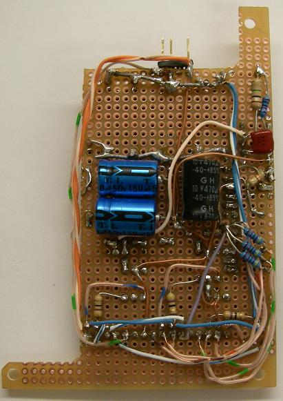 This is so ugly I have no idea why I'm showing you  I did some back-of-the-envelope calculations, and I think my line-voltage->5V regulator is approximately 2.2% efficient. It's not a big deal as the power draw isn't huge, and I think the paralled 2W resistors should be a-okay. One of my EE professors came into lab to see what I was tinkering on, looked at the project, looked at the calculations on the white board (including the drawn schematic), and after pondering this monstrosity for a few minutes said something along the lines of "If you show that to an electrician, he will never respect you again," and then walked out. I wonder if the same applies to EE professors I was working on the firmware a bit today, it seems like it is going to work! I hope this is what you were imagining Bush Ant, it was a fun idea to put together. I've only blown 2 fuses and popped the breaker once (all through sloppy probing). EDIT: I vote microprocessor with a lot of memory and a DAC and a small amp. Install it between the current circuit and the speaker - when it sees the attempt to drive the speaker, it starts dumping values out through the DAC into a simple amp that then drives the speaker in turn. Seems like it would work. Delta-Wye fucked around with this message at 07:01 on Apr 5, 2009 |
|
#
?
Apr 5, 2009 06:57
|
|
|
oh dear god you actually built it???!?!! that schematic I posted was meant to be a parody of a power supply than an actual one. like the advice to use thin green branches from trees as replacement spark plug leads if your 1000km from anyone and your leads happen to break (which actually does work for about 5 minutes untill they dry out due to resistive heating and catch fire in your engine bay) I can only see this ending badly, very very badly.
|
|
#
?
Apr 5, 2009 09:55
|
|
|
There are no words.
|
|
#
?
Apr 5, 2009 10:20
|
|
|
Delta-Wye posted:Here is a circuit only a mother could love! what the christing rear end  You know, you could definitely fit a small switching supply in that large an amount of space. There are toroidal transformers that are smaller than that bank of resistors. I didn't really think about it when you first posted, because I have a hell of a time visualizing things. I'm really terrible at it. But now I can see how much space you have to work with.
|
|
#
?
Apr 6, 2009 07:09
|
|
|

|
| # ? Jun 3, 2024 22:27 |
|
|
This may be a stupid question, I may be a stupid person. Regardless, I've got this question: http://zaphaudio.com/WaveguideTMM-minimalist-crossover.gif This is a schematic for a crossover for a speaker. Thing is, I've not previously seen one such as this, where all "routes" terminate to ground. Does this mean they all actually terminate to the (-) wire of the speaker input? I cant see this circuit working ANY other way; but I cant find any reference to similar style schematics. Thanks!
|
|
#
?
Apr 7, 2009 14:07
|
|