


|
Bad Munki posted:Force sensor stuff Take a look at something like this: http://search.digikey.com/scripts/DkSearch/dksus.dll?Detail&name=LT1920CN8-ND It might be cheaper to use 3 discrete opamps but this is the canonical case for an instrumentation amplifier and it will minimize your fabrication effort. Also, watch out for DC bias issues at the differential inputs and noise. Noise can probably be mostly taken care of by a strategically placed capacitor or by oversampling and averaging in the digital domain. I'd probably also be sure to use a solid linear-regulated reference voltage across the bridge. sixide fucked around with this message at 23:05 on Mar 5, 2011 |
 #
?
Mar 5, 2011 23:02
#
?
Mar 5, 2011 23:02
|
|


|

|
| # ? May 28, 2024 22:45 |
|
|
Cyril Sneer posted:So this implies that coaxial shielding functions as a result of the skin effect and not field cancellation. Why then do many sources claim that it is necessary to ensure that the centure conductor current must all be returned on the shield lest we end up having normal rather than differential current flow? It's been a while since I've taken an e-mag class, so bear with me. I believe that, under normal circumstances, the field lines terminate between the center conductor and the shield. Now, I'm not quite sure what you mean by "field cancellation" but this does not at all mean that both the shield and center conductor are radiating but in opposite phase. When you have a common mode current (i.e. current is flowing through the shield and center conductor in the same direction), some of the electric field lines do not terminate between the shield/conductor. Instead they terminate in whatever else is around them, leading to radiated energy.
|
|
#
?
Mar 6, 2011 01:34
|
|
|
Topical image concerning the coax discussion:
|
|
#
?
Mar 6, 2011 05:41
|
|

|
Cyril Sneer posted:Now assume the load is mismatched. Reflections occur, causing some phase shift between the forward and reverse currents. This results in a standing wave along the line. For a given infinitesimal length, the current on the centre conductor and the reverse current on the inner shield are no longer equal and opposite. Field cancellation does not occur and the line now radiates.
|
|
#
?
Mar 6, 2011 06:33
|
|


|
Corla Plankun posted:Topical image concerning the coax discussion: Sir are you suggesting that audiophiles are full of poo poo?! Surely if we put five dollars of electronics in a wooden box, it becomes worth $350, right?
|
|
#
?
Mar 6, 2011 06:41
|
|
|
ANIME AKBAR posted:Sir are you suggesting that audiophiles are full of poo poo?! Hahahahaha is that an altoid tin amp with a machined mahogany facade? My wallet 
|
|
#
?
Mar 6, 2011 07:29
|
|
|
 Altoid tin amps are probably better. This is the sort of thing you knock out in 10 minutes with a Monday morning hangover.
|
|
#
?
Mar 6, 2011 08:44
|
|
|
Love the use of that high end JR4556 opamp for driving 32 ohm phones.
|
|
#
?
Mar 6, 2011 17:50
|
|
|
sixide posted:
I laughed but I would have laughed harder if it was an LM386.
|
|
#
?
Mar 6, 2011 19:58
|
|

|
Been working on this R/C and USB project but, since I'm out of budget for now, I'm moving forward with the software side using a leftover board I built a while back for another project since it uses the same MCU as the future project. I'm trying to set up ICSP to make development safer on the MCU's puny little pins. I have a PICKit 2 programmer and I'm using the kit's software. The problem: I can't get the programmer to recognize the MCU. The target MCU has some blinker test code in it so I can confirm it still works. I can power the target board through USB or through the ICSP pins and it blinks fine. I tried shortening the ICSP cables to less than a couple of inches (since I couldnt find the suggested length) as the user's guide mentioned that they should be as short as possible. What am I doing wrong? Please help. Here's a schematic of the target board. A bit of a rush job, I'm sorry.  Thank you! PS: I realize that, this being a USB project, I could just use a bootloader. But I didn't have the proper parts to add a button to the board and this seemed better for some reason I can't quite remember. Still want to get it working though.
|
|
#
?
Mar 6, 2011 20:23
|
|
|
CptAJ posted:Been working on this R/C and USB project but, since I'm out of budget for now, I'm moving forward with the software side using a leftover board I built a while back for another project since it uses the same MCU as the future project. I'm not sure if you have something fancy going on with the ICSP header, but your wiring is all hosed up. I assume that if you were intentionality not following the PICKit2 cable layout, you would have specified, so match your connections up to the docs and see if it works better. 
|
|
#
?
Mar 6, 2011 20:37
|
|

|
babyeatingpsychopath posted:This appears to be a diversion regulator. When the battery is full, it dumps any power to a shunt load. If the turbine voltage is less than battery voltage, the blocking diode prevents the battery from spinning the turbine, so no, it will not charge the battery if the turbine is less than battery voltage. Thanks. Now that I think about it, my question about the <12v charging was silly, as the purpose of the diode is to make sure it only goes one way. Another question: today we found out that he has a SCR. How can we connect the gate wires so it behaves like a blocking diode? I'm not really sure what the difference between an SCR and a regular diode is.
|
|
#
?
Mar 6, 2011 21:27
|
|
|
Delta-Wye posted:I'm not sure if you have something fancy going on with the ICSP header, but your wiring is all hosed up. I assume that if you were intentionality not following the PICKit2 cable layout, you would have specified, so match your connections up to the docs and see if it works better. Well, I'm actually using an SE2-USB programmer. Which I understand is a clone of pickit2 (uses the same software too). Here are the instructions provided for it:  That should make more sense. The wiring is fine, as you can see. Any other ideas? I gather I don't need the resistive/diode isolation of the VPP pin because I'm not using the MCLR functions on the board.
|
|
#
?
Mar 6, 2011 22:54
|
|
|
CptAJ posted:Well, I'm actually using an SE2-USB programmer. Which I understand is a clone of pickit2 (uses the same software too). Here are the instructions provided for it: I think the PICKit2 uses the reset line to enter into programming mode, you might try adding the pullup circuitry and seeing if that changes the behavior.
|
|
#
?
Mar 6, 2011 23:05
|
|
|
CptAJ posted:Well, I'm actually using an SE2-USB programmer. Which I understand is a clone of pickit2 (uses the same software too). Here are the instructions provided for it: I think if you connect it up like in the instructions you posted it should work. All 5 connections.
|
|
#
?
Mar 6, 2011 23:09
|
|
|
Unparagoned posted:I think if you connect it up like in the instructions you posted it should work. All 5 connections. I must have traced the circuit out a million times now, and this is killing me - what is missing? It looks like it is connected correctly according to the (minimalist) provided connection diagram.
|
|
#
?
Mar 6, 2011 23:44
|
|
|
Delta-Wye posted:I must have traced the circuit out a million times now, and this is killing me - what is missing? It looks like it is connected correctly according to the (minimalist) provided connection diagram.
|
|
#
?
Mar 7, 2011 00:40
|
|
|
 New schematic. I was tired and rushed. Made some mistakes on the other one. Surprised no one noticed the lack of decoupling and VUSB caps =P
|
|
#
?
Mar 7, 2011 07:45
|
|
|
Delta-Wye posted:I think the PICKit2 uses the reset line to enter into programming mode, you might try adding the pullup circuitry and seeing if that changes the behavior. I use an ICD3 so I don't have any experience with the PICKit2, but the lack of a pullup resistor on MCLR jumped out at me. The ICD3 needs one, so maybe the PICKit2 needs one as well?
|
|
#
?
Mar 7, 2011 08:55
|
|
|
Solved it. The pinouts were the problem. The PGD and PGC pins were inverted on the programmer's user guide. I used the PICKit2's app to individually pull up and test the pins and found the problem. A quick rewire fixed the problem and the MCU is showing up now. No need for the isolation circuit. Thanks a bunch for the ideas guys! You rock.
|
|
#
?
Mar 7, 2011 20:00
|
|
|
Ok, so I have this hackshit of a schematic: 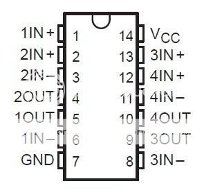 Is there another opamp I could use in place of that one to save space? I wish I knew more about this stuff
BlackMK4 fucked around with this message at 22:03 on Mar 7, 2011 |
|
#
?
Mar 7, 2011 21:53
|
|

|
BlackMK4 posted:Ok, so I have this hackshit of a schematic: havent been able to find anything less than a 14-pin norton op amp, though im not sure what its for. they have them surface mount though
|
|
#
?
Mar 8, 2011 06:47
|
|
|
BlackMK4 posted:Ok, so I have this hackshit of a schematic: The LM3900 is a pretty special op-amp. There might be another way to do whatever it is you're doing with a LM741 or something, but there isn't anything (to my knowledge) that you can just drop into the LM3900's place. You'll have to either use that or redesign.
|
|
#
?
Mar 8, 2011 07:04
|
|

|
Thank you both, was worth the shot ")
|
|
#
?
Mar 8, 2011 07:11
|
|
|
Oh god why would anyone seriously suggest the 741?! Yes, it was interesting in class as a historical footnote, but jesus please never ever use these. Never ever.
|
|
#
?
Mar 8, 2011 07:19
|
|
|
Slanderer posted:Oh god why would anyone seriously suggest the 741?! Well, forums poster Slanderer, my professor for EE 201 told me they were ideal. I paid a lot of money for that class, why should I believe you?  fakedit: Also, the professor probably predated the 741 by at least half a century and was still waiting for that "solid-state-craze" to blow over 
|
|
#
?
Mar 8, 2011 08:07
|
|
|
Slanderer posted:Oh god why would anyone seriously suggest the 741?! My three op-amp courses was taught by two guys who retired literally right after those classes finished and did not give a gently caress 
|
|
#
?
Mar 8, 2011 08:52
|
|
|
Heh, we spent a lab or so measuring some of the characteristics of the 741, and then immediately switched to a newer LF411 and did the same, just to show how crappy the 741 was (and the LF411 isn't even that good anymore). Dual power supplies, and no rail to rail output? Jesus, man. Nowadays, I just use a plethora of whatever-the-gently caress I have stored away. Probably working from a 3.3 or 5V single supply. If I use a dual op amp chip, it will probably be just to generate a virtual ground of like Vcc/2 to bias the signal or whatever. I'm so goddamn spoiled by brand-new op amps, with no noise, huge cutoff frequencies, staggering input impedances, negligible bias current and offset voltage, and basically no real temperature variation. Not to mention that it could probably get enough supply current from you staring at it hard enough. Oh, and they take ESD like a champ. God bless you, analog IC designers. God loving bless you. On an unrelated note: audiophiles who are spergy enough to swap out op-amps inside equipment are hilarious, as I've read about guys swapping out new chips with fantastic frequency responses with lovely ones that give all kinds of distortion. And then saying things like" ____ chip gives a richer sound!". No it doesn't, its just making GBS threads itself when you turn the volume up.
|
|
#
?
Mar 8, 2011 19:33
|
|
|
Slanderer posted:God bless you, analog IC designers. God loving bless you. loving wisdom
|
|
#
?
Mar 8, 2011 21:30
|
|

|
I really was not sure where to post this, but I think this is the best place. This video is awesome and should appeal to the Mech-E and Elec-E in all of us. http://www.youtube.com/watch?v=VqfMl0lBX0s
|
|
#
?
Mar 8, 2011 22:00
|
|

|
Slanderer posted:God bless you, analog IC designers. God loving bless you. RIP Bob Widlar: Drink all night, change the world all day. Also, current regulating diodes are pretty awesome but stupidly expensive. If you're clever enough you can find a $0.50 JFET that will give you the fixed current you want. Then you can bias zeners and signal BJTs all day. The 2N5457 will give you ~3.8mA from ~2V to maximum (25V). Also you can drop a resistor between your gate-source jumper and the source to reduce it. Too bad I discovered this while working on a +/- 60VDC power supply which is mostly out of the operating range of cheap JFETs. sixide fucked around with this message at 23:18 on Mar 8, 2011 |
|
#
?
Mar 8, 2011 23:09
|
|
|
Slanderer posted:Heh, we spent a lab or so measuring some of the characteristics of the 741, and then immediately switched to a newer LF411 and did the same, just to show how crappy the 741 was (and the LF411 isn't even that good anymore). Dual power supplies, and no rail to rail output? Jesus, man.
|
|
#
?
Mar 9, 2011 07:03
|
|
|
Speaking of old parts, has anyone ever compiled a timeline of the release dates of common parts and who manufactured them first? I have an old textbook from 1970 that uses the 741, the 1N4001 series, and the 2N3904 in examples so obviously they predate the book, but I don't know where to find anything more specific. Also, how can I determine if a diode is fast enough for a particular switching regulator if I know the frequency and duty cycle?
|
|
#
?
Mar 9, 2011 18:19
|
|
|
I've got a boost pump circuit based based using a PIC as a brain. The only problem is that it seems like I've made a quantum computer. I'm using an oscilloscope to work out if it's working, etc. I have probes x100 on over the capacitor to see if it's charging. The capacitor won't charge. So I use a second probe X10 to see what's going on elsewhere to find out why it's not working. As soon as I try and measure anything the capacitor starts charging. I was measuring the base of a transistor. I've also removed the first probe when making the measurement with the second probe, it still causes the circuit to charge. If I use a X100 probe to make a measurement then the circuit doesn't change it's behavior. The circuit is pretty much as standard DC/DC charge pump but with a PIC18F generating the signal. (Yeh it's probably not the best way to do it). The oscilloscope is a tektronix 2445A. I've worked out why the circuit doesn't work without any measurements. But I can't figure out how the x10 probe makes the circuit work. So basically what effects do oscilloscopes have on the circuit you are measuring?
|
|
#
?
Mar 9, 2011 19:25
|
|
|
Do you have a load, even just a resistor, on the output? Power converters tend to act funny when they're unloaded, but gently caress if I know how else to explain what's going on there. And there's nothing wrong with using a PIC in a power supply! Microchip even makes a series designed for power supplies: PIC18F4331/4431 (40 pin) and PIC18F2331/2431 (28 pin). They've got a bunch of PWM generators with complementary outputs and a higher-speed ADC with simultaneous dual-sampling. Pretty neat if you're making a smart power supply.
|
|
#
?
Mar 9, 2011 19:50
|
|
|
Unparagoned posted:I've got a boost pump circuit based based using a PIC as a brain. The only problem is that it seems like I've made a quantum computer. Do you have a schematic?
|
|
#
?
Mar 9, 2011 21:45
|
|
|
SnoPuppy posted:Do you have a schematic? I do now, with the help of paint. So if I used the probe on the right side of D1 C would start charging to 100V. Using a 100X probe showed that the diode D1 I put there to protect my pic so I didn't blow another one up meant that T2 wouldn't switch.
|
|
#
?
Mar 9, 2011 22:22
|
|
|
Unparagoned posted:I do now, with the help of paint. So if I used the probe on the right side of D1 C would start charging to 100V. I would probably have a resistor instead of D1, and an additional base resistor on T1. The probe could be adding capacitance wherever you are touching it. I would also add some series resistance because your initial current draw to the uncharged capacitor is going to be very large, potentially damaging parts of your circuit.
|
|
#
?
Mar 9, 2011 23:03
|
|
|
Unparagoned posted:I do now, with the help of paint. So if I used the probe on the right side of D1 C would start charging to 100V. Yeah, you'll definitely want to change D1 to a resistor. Right now there's no ohmian resistance at all between your PIC supply and ground, so weird stuff will happen. That's all I would change at first, actually. A base resistor at T1 shouldn't be necessary because of R2, and a resistor in series with C will affect what you're trying to do. There shouldn't be a significant initial current spike at C because the inductor has an inverse charge/discharge waveform. D1 isn't actually doing anything, because the base junction of the transistor has much the same effect
|
|
#
?
Mar 9, 2011 23:18
|
|
|

|
| # ? May 28, 2024 22:45 |
|
|
Unparagoned posted:I do now, with the help of paint. So if I used the probe on the right side of D1 C would start charging to 100V. As others have said, put a base resistor on T2 instead of a diode. Something like 5-10k would probably be good. Second - It looks like you've made an unregulated boost converter. This may be what you're going for, but it's not a charge pump. Charge pumps don't have any inductor in the switching path - they use capacitors as the primary energy storage, with diodes to direct charge flow. Lastly, the collector of T2 is on what could be a high voltage node. Are you sure this won't damage your transistor?
|
|
#
?
Mar 10, 2011 06:27
|
|