


|
Pollyanna posted:Christmas is coming up, and I wanted to get myself some Arduino swag so I can really dive into it. I like flashy stuff like LEDs and LCD screens and music makers, but I also want to branch out to more advanced stuff. What are some good books/learning resources I can buy? Are there any particularly cool components people here would recommend? I'm looking for the same stuff as well. I have an Arduino R2 and a bit of pre-cut jumper wire, but I somehow forgot to get any fun bits to make it actually do something. 
|
 #
?
Dec 15, 2014 03:51
#
?
Dec 15, 2014 03:51
|
|

|

|
| # ? May 31, 2024 08:15 |
|
|
The accessories you'd want to pair with an Arduino (along with any supplemental reading materials) depends highly on what it is you're interested in doing. If you just want to blink some lights, 74HC595 shift registers are a standard classic and there's tons of material to go along with them. (Don't forget some decoupling capacitors if you're planning on hooking up more than about two in series.) LEDs naturally require resistors and wiring, and if you're running a lot of stuff, you may need an external power source. RGB LEDs are good way to get your feet wet with pulse width modulation. Servos are pretty standard (start with small ones and buy more than one because you will break at least one, I can almost guarantee it) if you're interested in making things move, as are stepper motors and just straight DC motors. You can do some interesting sensor projects with thermometers, magnetometers, accelerometers, gyroscopes, force sensitive resistors, and/or ultrasonic range sensors. Push buttons (either momentary or non-momentary), 10K potentiometers, rotary encoders, and toggle switches are all good for handling basic user input, and they pair well with LCDs. For just about all of those input methods (except the 10K pot), I'd recommend some 10K fixed resistors and 0.01uF capacitors to build a basic debouncing circuit. The more common yet more advanced add-ons tend to be ethernet or wi-fi connectivity, data logging to SD cards, and bluetooth connectivity. If you're interested in computer interfacing, the normal go-to is to use Processing, and there's tons of example projects on interfacing Processing sketches with Arduino projects. If you don't have one already, get a decent digital multi-meter (preferably with audible continuity testing). While the Arduino is pretty bread-board friendly, you'll soon want a soldering iron. Really, though, if you're looking for what accessories you want, figure out some things you'd like to try to do and then ask for suggestions. You'll get much better focused suggestions. The Arduino site and forums, Sparkfun, Adafruit, Instructables, and HackADay are all filled with project ideas if you're looking for something to make you go "Oooh! Neat!"
|
|
#
?
Dec 15, 2014 04:29
|
|
|
Browse around for projects on sites like https://learn.adafruit.com/ for some ideas too.
|
|
#
?
Dec 15, 2014 06:51
|
|
|
Pollyanna posted:Christmas is coming up, and I wanted to get myself some Arduino swag so I can really dive into it. I like flashy stuff like LEDs and LCD screens and music makers, but I also want to branch out to more advanced stuff. What are some good books/learning resources I can buy? Are there any particularly cool components people here would recommend? 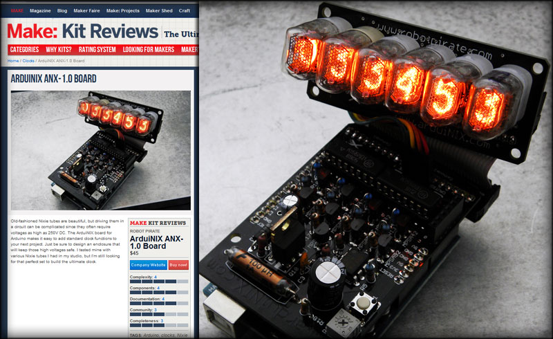 Sure, I'll use this opportunity for a shameless plug. Nixies predate LED and LCD though... https://www.arduinix.com
|
|
#
?
Dec 15, 2014 16:06
|
|

|
TheLastManStanding posted:Serial.print(x) Thanks for that. Makes everything much nicer. I've been messing with a Piezo buzzer and some buttons and trimmers. I'm not sure if I'd call it a proper synth since I'm just using tone(), but it's fun. Is there a beginner-friendly kind of way to get more interesting sounds out of a buzzer? And I think I know the answer to this, but Arduino code will always run in one single loop right? Or can you have stuff like multiple while loops trigger simultaneously/independently?
|
|
#
?
Dec 15, 2014 18:24
|
|

|
The arduino is single threaded, but that doesn't mean you can only do one thing at a time. With interrupts, you can get the arduino to drop what it's doing and do something right away (after a timer runs out or a pin is pulled high or low after you set an interrupt). http://playground.arduino.cc/Code/Interrupts There's a synthesizer plan on sparkfun. https://learn.sparkfun.com/tutorials/build-an-auduino-step-sequencer You might also want to Google the Atari Punk Console for a simple audio toy you can make out of two 555 timers and simple components. It's not an arduino project, but it's still fun. TVarmy fucked around with this message at 00:43 on Dec 16, 2014 |
|
#
?
Dec 16, 2014 00:41
|
|


|
Nice yeah those look fun. As far as the single threaded thing goes, I guess you just need to make sure everything you need is looping at all times. I've started using millis() in place of delay() which seems like a good idea. Requires a little more thought though. I came up with what I think is a pretty neat idea for a project too- pong on an 8x8 led matrix with a PS2 joystick and a scoreboard. It's not anything crazy but getting it working should be rewarding. Then after that I want to do something with my gyroscope.
|
|
#
?
Dec 16, 2014 01:42
|
|
|
Got myself my first Arduino nano clone. �2 from China.. Dinky little thing!
|
|
#
?
Dec 16, 2014 14:31
|
|


|
mod sassinator posted:Browse around for projects on sites like https://learn.adafruit.com/ for some ideas too. I was looking around and I actually found your kitty in one of the articles 
|
|
#
?
Dec 16, 2014 20:07
|
|


|
nonentity posted:
How easy would it be to adapt your board to different nixies? (Only just starting to look into this).
|
|
#
?
Dec 17, 2014 03:08
|
|

|
ImplicitAssembler posted:How easy would it be to adapt your board to different nixies? (Only just starting to look into this). Oh it runs any Nixie tube. I just have the IN-17s in as a stock setup.
|
|
#
?
Dec 17, 2014 03:48
|
|
|
nonentity posted:Oh it runs any Nixie tube. I just have the IN-17s in as a stock setup. What's the difference between the V1 and V2? (And when will you have the V2 back in stock?)
|
|
#
?
Dec 17, 2014 04:22
|
|
|
ImplicitAssembler posted:What's the difference between the V1 and V2? (And when will you have the V2 back in stock?) V2 has a few edits and new features that were asked for over the course of the years I have been offering the original kit. Namely, better parts layout, shorter total height, better power circuit, less signal noise, exposed input/output header, better labeling, etc. The parts load out is the same except for capacitor C3, which in the V1 kit, is a 1pF cap, but in the V2 it is a 47pF cap. That parts difference is a result of one of the reasons I went ahead wih the V2. The original circuit was very sensitive to manufacturers part tolerances, and I was constantly having to adjust the cap at C3 to make up for those variances. V2 should be much more resilient. I should have a new batch of V2 kits in a week or so, my manufacturer has a lead time of 8 days, and I think I ordered a new batch 4 days ago.
|
|
#
?
Dec 17, 2014 04:34
|
|
|
Anyone have any experience with logic analyzers? I'm using a lot of I2C/SPI/serial/USB and I'm tired of using my 2 channel digital oscilloscope for it.
|
|
#
?
Dec 17, 2014 20:32
|
|


|
Yeah the Saleae analyzers are really nice in my experience. If you're doing low level I2C, SPI, etc. it's a huge step up from using a scope. The software has nice features like decoding those bus messages so you can more easily figure out what's going on. For I2C in particular it's really, really handy since it's a somewhat complicated protocol. $100 for a logic 4 or $200 for the logic 8 is a great price. EEVblog has a good teardown and review: https://www.youtube.com/watch?v=7OCPWCdg2ys
|
|
#
?
Dec 18, 2014 00:52
|
|
|
Does anyone know of a guide on wiring up an 8x8 LED matrix with a MAX7219 or something similar? I've found two. With the first one I'm getting all 64 LEDs to light up, but none of the code I try does a thing to it from there. With the second one, which seems much better, I'm a little unclear on how to follow this: The numbers are all out of whack. I have the 7219 datasheet so I know the pins there, but I don't know where which numbers are on my 8x8. How finicky are these things if I have the wires going to the wrong places? Would that prohibit any control but still light them all up?
|
|
#
?
Dec 19, 2014 21:56
|
|
|
The Royal Scrub posted:Does anyone know of a guide on wiring up an 8x8 LED matrix with a MAX7219 or something similar? I've found two. With the first one I'm getting all 64 LEDs to light up, but none of the code I try does a thing to it from there. With the second one, which seems much better, I'm a little unclear on how to follow this: I'm not exactly sure how the matrix is set up but I'm guessing that one bank of connections on it is the common anodes, and the other cathodes with them running perpendicular to each other. DIG0-7 should be on the common cathodes (ground) and SEG0-7 should be on the anodes (positive). When two pins that are perpendicular to each other turn on, the LED at that point will turn on. For example: DIG2 and SEG2 will intersect at LED (2,2). When they are both turned on with the 7219, that LED will light up as SEG2 will source current to it and have a ground path through DIG2 that sinks it. Edit: Do you have the data sheet for the LED matrix or a link to where you got it? I'm guessing it has a shift register in it or something so that each LED can turn on independently. Also thanks for the suggestion on the logic analyzer, that's the one that was I leaning towards as well. Now to decide if I want to pay the extra $200 to get one that goes up to 100 MHz. Woolwich Bagnet fucked around with this message at 03:19 on Dec 20, 2014 |
|
#
?
Dec 20, 2014 00:38
|
|
|
nonentity posted:V2 has a few edits and new features that were asked for over the course of the years I have been offering the original kit. Scratch that, they're here... http://www.arduinix.com/Main/Store.htm
|
|
#
?
Dec 21, 2014 00:00
|
|
|
Stealth Like posted:Edit: Do you have the data sheet for the LED matrix or a link to where you got it? I'm guessing it has a shift register in it or something so that each LED can turn on independently. I don't and that's mostly the problem. The china kit I bought came with zero documentation, and the LED dot matrix is stamped with SH1088AS, which doesn't pull anything up on Google. I found a datasheet for an 8x8 LED dot matrix, which helps me understand how it works, but that's about it. I have it wired up and working now, but I have two problems. One is that when it's supposed to be all clear, 4 dots are on, 2 rows and 2 columns. Second is that my letters don't look like they should when I run the code. I'm pretty certain this means I have wires going to the wrong places, but there are too many possible combinations to start pulling wires out and sticking them random places. I really don't get why 2 rows and 2 columns are on when they should all be cleared.
|
|
#
?
Dec 21, 2014 18:47
|
|
|
The Royal Scrub posted:I don't and that's mostly the problem. The china kit I bought came with zero documentation, and the LED dot matrix is stamped with SH1088AS, which doesn't pull anything up on Google. I found a datasheet for an 8x8 LED dot matrix, which helps me understand how it works, but that's about it. If it's anything like this fellow....  I had to diagram the pinout by trial and error, as there was no datasheet available...  Once I knew which anode supplied which numeral position, and which cathode supplied which segment, I could multiplex them all..  Although I had to write my own font. http://youtu.be/hokNvhYrYLw And controlling each alphanumeric position required a lot of futzing... http://youtu.be/nelbQkZE-7Q I eventually got all the characters working... http://youtu.be/94aekVkjfRs The short version is, make notes, decipher the pinout and write a font. It's tough work but it's worth it. I love bringing these vintage displays back to life. nonentity fucked around with this message at 21:40 on Dec 21, 2014 |
|
#
?
Dec 21, 2014 21:38
|
|
|
Decipher the pinout and make notes was the correct approach. These things are just in random places lol Thanks once again for some guidance.
|
|
#
?
Dec 22, 2014 01:13
|
|
|
Is this a good value in a starter kit? It seems like most of the other components are pretty cheap (breadboard, cables, etc), so I'm not sure if the extra $40 is worth the components you get. I know you can get separate general electronics components, but would you just end up having to grab a bunch of specific IC's and things to make most projects and have it come out the same anyway? Would this kit, or a general electronics kit + Arduino work better? What types of components would I be looking for in a general electronics kit for an Arduino? edit: Kit components ($55) 1X Arduino Uno R3 1X Arduino & Breadboard Holder 1X Bread Board 1X Shift Register 2X P2N2222A Transistors 2X 1N4148 Diodes 1X DC Motor with wires 1X Small Servo 1X 5V Relay 1X TMP36 Temp Sensor 1X 6' USB Cable 65X Jumper Wires 1X Photocell 1X Tri-color LED 10X Red LED 10X yellow LED 1X 10K Trimpot 1X Piezo Buzzer 2X Big 12mm Buttons 45X 330 Resistors 45X 10K Resistors PRADA SLUT fucked around with this message at 10:05 on Dec 23, 2014 |
|
#
?
Dec 23, 2014 09:40
|
|

|
Looks pretty good to me, it has all kinds of little devices to experiment and learn from using the Arduino. I think that kit would take you pretty far in getting started, then you can pick up individual parts as you need them.
|
|
#
?
Dec 23, 2014 09:49
|
|
|
There's one thing I want to note. You don't really want to scrimp too much on breadboards if you buy one separately. The cheap ones can have such stiff springs that it's near impossible to insert components without damaging them, which kind of ruins the point of prototyping.
|
|
#
?
Dec 23, 2014 16:23
|
|
|
Do yourself a favor and order one of those 128x64 pixel 0.96 OLED displays with the I2C interface (uses fewer cables) off of ebay, they're about $5 shipped from china and give you a Nokia style display without the power or space requirements and has equally wide driver support from Adafruit and U8Glib. The SPI interface model is technically faster but I2C is zero config and uses 3 fewer cables (4 vs 7)
|
|
#
?
Dec 23, 2014 17:02
|
|


|
Yeah I'd say get the kit that comes with an actual book if you'll use it. I bought one for $64 that has more parts for sure, but the trade-off is that the documentation is just a dropbox of 25 lessons in Engrish and copy/pasted code full of formatting problems. It was fine at first when things are simple, but even if their poo poo works it doesn't really help you learn why. The dropbox for reference, in case anyone is curious.
|
|
#
?
Dec 23, 2014 23:12
|
|
|
I wouldn't be concerned about a book, when there's a ton of free material online that's really quite good. https://learn.adafruit.com/category/learn-arduino for example.
|
|
#
?
Dec 25, 2014 07:30
|
|

|
Hey guys, my only experience with soldering electronics is assembling an EDtracker (using an MPU9150 breakout & pro micro), but I think I've found my first real project. Essentially I want to have a rotary encoder report and display (live, in feet/inches) distance on a PC, nothing fancy. Specifically I'll be using it to display/record paper usage (paper remaining/total used) on a roll fed, wide-format printer. Ideally it would only record when the encoder is moving clockwise. I know I'll have to do some math, but I was wondering if anyone has seen a project like this? I'd appreciate any tips or a push in the right direction. I've already ordered this rotary encoder and a Leonardo.
|
|
#
?
Jan 6, 2015 13:26
|
|


|
Remember to scale your calculation down as the paper depletes. For instance, 1 revolution on a full roll gives more paper than one revolution on a near-empty roll.
|
|
#
?
Jan 6, 2015 20:49
|
|
|
PRADA SLUT posted:Remember to scale your calculation down as the paper depletes. For instance, 1 revolution on a full roll gives more paper than one revolution on a near-empty roll. The encoder will be contacting the paper after it's already off the roll and being fed onto the tray. I'll try to take a photo today.
|
|
#
?
Jan 6, 2015 22:21
|
|
|
From an engineering standpoint then, I would put some sort of wheel or something over the axle of the encoder that increases its circumference, which makes it spin a little slower and makes your encoder less likely to "skip" on a paper slide. What I would do (and I'm not familiar enough with the type of encoder to give you an exact code, but it looks like the encoder understands its directionality) is spin the encoder one full time and see what data it outputs. Then, figure out which piece of data you want to use (that is generated once per rotation), and have your code look for that, keeping it in another variable. Set up one of your pins as a digital (or analog, whatever the encoder returns) input, and have it input that data into encoderData (for this example, if the encoder returned 1 once per rotation). Figure out how much paper there is in a roll, and use the circumference of the encoder axle wheel to determine how many rotations the encoder will go through before the paper is empty (say, 500 here, like the circumference of the wheel was one foot, and there's 500 feet in a roll). C code:You could even put something like if rollRemaining < 10 digitalOut, to make a light engage when it's time to replace the roll, and a button that resets the counter when the roll is replaced. PRADA SLUT fucked around with this message at 02:34 on Jan 7, 2015 |
|
#
?
Jan 7, 2015 02:24
|
|
|
Be careful about using too big of a wheel. The precision of the encoder will be in terms of rotation (+/- 1 degree for instance), so using a bigger wheel will result in more uncertainty in the calculated length. The best arrangement would be a small, sticky wheel.
|
|
#
?
Jan 7, 2015 02:56
|
|


|
Man, thanks for the help, I'll give this a try once I have everything in front of me. As far as size of the wheel, I think it just needs to be slightly or exactly the same diameter as the body if the encoder. I'll take a photo of the mounting area if I can.
|
|
#
?
Jan 7, 2015 06:02
|
|
|
Is there a site for dirt cheap components shipped from China or wherever? Like a monoprice for components?Google Butt posted:Man, thanks for the help, I'll give this a try once I have everything in front of me. As far as size of the wheel, I think it just needs to be slightly or exactly the same diameter as the body if the encoder. I'll take a photo of the mounting area if I can. The important thing on the code is that you must know exactly what data values your encoder outputs, (and you can figure that out by just hooking it up to a console window and writing down what values output as you turn it by hand), since that will determine the looping structure of your program. For example, if the encoder didn't output a directionality, just a rotational position, you would have to put a nested if statement to differentiate between it moving forward or backward in the loop. For the encoder, if the wheel is too small, it may not catch the paper completely and your rotations might be off if the paper slides. Also, your circumference measurement margin of error decreases as the wheel size increases. For example, making a .1cm measurement error is far more significant on a 1cm circumference 100cm, as those as it represents a smaller percentage of each rotations linear distance. Optimally, you want a wheel circumference that is proportionate to the degree of precision in which your rotary encoder can resolve. edit: I noticed a possible error with the code. If the encoder only outputs one "tick" when it's turned, it's fine as-is. However, if the encoder outputs a constant "stream" of ticks, your if loop will have to make sure that it only counts up one time per change, otherwise if the encoder is just resting in a certain position, it will be giving back data nonstop to the Arduino, making it erroneously count up. The modified if would be something like: code:PRADA SLUT fucked around with this message at 08:56 on Jan 7, 2015 |
|
#
?
Jan 7, 2015 08:39
|
|
|
withak posted:Be careful about using too big of a wheel. The precision of the encoder will be in terms of rotation (+/- 1 degree for instance), so using a bigger wheel will result in more uncertainty in the calculated length. The best arrangement would be a small, sticky wheel. As for the code, sparkfun and google have a million examples and it should be very easy to make them fit your need. The main thing is to make sure you are using interrupts to be certain you don't miss any updates. PRADA SLUT posted:Is there a site for dirt cheap components shipped from China or wherever? Like a monoprice for components?
|
|
#
?
Jan 7, 2015 09:02
|
|
|
TheLastManStanding posted:DigiKey if you want a place you can trust. Ebay if you're willing to gamble on lower prices. I'm looking specifically for relays, laser diodes, servos, and assorted transistors.
|
|
#
?
Jan 7, 2015 09:39
|
|
|
My plan is to order a few different knobs and some rubber bands to wrap around it (I think that should be sticky enough). Might as well order some digital calipers while I'm at it. Here's where I'm planning on mounting it, regular bearing for scale.  
|
|
#
?
Jan 7, 2015 09:49
|
|
|
TheLastManStanding posted:Not really. The resolution of the encoder in terms of circumference traveled will go down, so the precision at any given point is slightly less, but that amount is negligible since it isn't cumulative. Doesn't the encoder output only rotation? It doesn't know anything about linear distance or circumference. withak fucked around with this message at 16:14 on Jan 7, 2015 |
|
#
?
Jan 7, 2015 16:00
|
|
|
withak posted:Doesn't the encoder output only rotation? It doesn't know anything about linear distance or circumference. Right, but I think he's just saying that using a large wheel isn't really a problem because yes, while feeding 1/100th of an inch along the wheel will produce very little rotation with the big wheel, vs. much more with a tiny wheel, leading to difference in accuracies of calculated lineal feed, that error doesn't actually matter, since it's not like it will build up over time. So with a tiny wheel on the encoder, your rotations->lineal feed result will give you a result with an error of, let's just say, oh, +/-.01", and with a very very large wheel, let's say the error is +/-.5". But who cares, it's a fixed error and not, as he said, a cumulative error, since the readout on the encoder is absolute, not relative.
|
|
#
?
Jan 7, 2015 16:07
|
|


|

|
| # ? May 31, 2024 08:15 |
|
|
Is it possible to say that the error won't be cumulative? There will definitely be a random component to it that won't be, but it is possible for mechanical devices to have a bias in one direction or another if they are measuring things in two directions. It probably doesn't matter, if the device is consistently underestimating or overestimating stuff then it could easily be adjusted for in the code.
|
|
#
?
Jan 7, 2015 16:15
|
|