


|
One thing to also take into account is that the Arduino is not going to retain information on how much was previously used if its power is removed. So if you think that either the batteries will not last long enough for entire rolls of paper to be used or someone will power it off or something then you'd need to look into additional stuff on how to store data on SD cards or whatever. And of course you'll want to make sure you've got some way to reset the current count for new rolls. If you're just keeping track of a single print job's consumption this might not be an issue however. ed: this might have been mentioned but it looks like that linked encoder outputs which direction it is traveling in somehow. If that's the case you can just not code anything to happen while it is in 'reverse' state and then while it's in 'forward' state then have the arduino count.
|
 #
?
Jan 7, 2015 16:26
#
?
Jan 7, 2015 16:26
|
|


|

|
| # ? May 28, 2024 13:25 |
|
|
The encoder link says it's a 200 pulse/rev Gray code. So there are 4 wires total, 2 will be signal lines that increment like: 00 01 11 10 00 In one direction and in the other: 00 10 11 01 00 Note that one bit changes between adjacent states. Gray codes are used frequently in embedded work where having 2 bits transition between states could be ambiguous. Without a Gray code if I read 01 then 11, did I miss 10 or merely catch the higher bit going up first? Someone was suggesting interrupts as well. If you're comfortable with that it's the way to go, otherwise you can do some napkin math to figure out how often you need to poll given your encoder's pulse rate and expected rate of paper feeding. A bigger wheel on the axle will effectively slow the pulse rate per inch measurement and let you check the values more slowly.
|
|
#
?
Jan 7, 2015 16:32
|
|

|
withak posted:Is it possible to say that the error won't be cumulative? There will definitely be a random component to it that won't be, but it is possible for mechanical devices to have a bias in one direction or another if they are measuring things in two directions. Encoders physically read position; it doesn't matter how many times you turn it, if you rotate it to the same position you'll get the same reading. This means that as long as you don't miss a bit change (which it is possible to miss), you will know exactly how much it has turned down to plus/minus whatever the resolution is. There might be some error at different positions through the rotation, but over the course of exactly 1 rotation, it is impossible for there to be any error. Where the important error comes in is when you multiply the error in your diameter by the rotations.
|
|
#
?
Jan 7, 2015 17:03
|
|
|
PRADA SLUT posted:Is there a site for dirt cheap components shipped from China or wherever? Like a monoprice for components? BangGood.
|
|
#
?
Jan 7, 2015 19:53
|
|

|
I have one question about laser diodes. I want to get a pack of laser diodes, basically just like the lasers that come in presentation pointers (not engraving lasers or anything like that). What specs should I be looking for on them? I'd rather not cannibalize some laser pens since it seems like diodes are way, way cheaper. 5mW 650nm?TheLastManStanding posted:Encoders physically read position; it doesn't matter how many times you turn it, if you rotate it to the same position you'll get the same reading. This means that as long as you don't miss a bit change (which it is possible to miss), you will know exactly how much it has turned down to plus/minus whatever the resolution is. There might be some error at different positions through the rotation, but over the course of exactly 1 rotation, it is impossible for there to be any error. Where the important error comes in is when you multiply the error in your diameter by the rotations. That's true, but that's not where the measurement error I was thinking of would lie. Let's say you take a measurement of the circumference of your axle (or a small wheel). You use your calipers (or a string wrap, or a ruler, whatever), and let's say you come up with a measurement of 1cm. However, if you have lovely calipers, or your ruler isn't lined up right, or for some reason, you make a small error, let's say this error is one tenth of a centimeter off. So your measured value is 1.0cm, and it actually is 1.1cm--an error of 10% (rounding all math in this example). Now, let's say you take a larger wheel and take the same measurement (and have the same error). This time, you measure your wheel to be 10cm (when it really should be 10.1cm). Again, a .1cm error, but this time, it only represents and error of 1%. The reason this error is manifest is because that the circumference measurement error will add up over time because it's being used to measure linear distance, not rotations. When you measure the roll of paper, you might say "oh, this paper is 1000cm long", so my wheel will rotate 1000 times before it's empty (1000cm [paper roll length] / 1cm [axis circumference]). However, it won't. The 0.1cm error will add up per rotation, making the roll deplete when only 909 revolutions have completed (1000 / 1.1), meaning your programs internal counter is off by around 10%, as expected from the initial margin of error during measurement. Conversely, if you use a larger 10cm wheel, and you do the math and write your program to expect 100 revolutions (1000 / 10), in reality, you will only get 99 revolutions (1000 / 10.1). However, 99 revolutions represents a smaller margin of error, using the larger wheel. Now your paper counter works within 1% accuracy, instead of 10%. If your initial measurements are perfect, that it's a moot point mathematically, but a larger circumference represents a smaller margin of error, for the same constant measurement error value. PRADA SLUT fucked around with this message at 22:01 on Jan 7, 2015 |
|
#
?
Jan 7, 2015 21:51
|
|

|
OP could avoid all of this headache by not attempting to do any theoretical calculations and just calibrating the finished device with a known length of paper.
|
|
#
?
Jan 7, 2015 21:53
|
|


|
withak posted:OP could avoid all of this headache by not attempting to do any theoretical calculations and just calibrating the finished device with a known length of paper. I don't believe our rolls are a consistent length. That's the other reason I want to do this, find out how long our rolls actually are. They should be 250'. I definitely only want to the encoder to count in one direction, the printer automatically reverses paper feed after every time it cuts a print. I'll have to look at a reset button for sure. Sleep modes/storing data I'll have to look into, but this is essentially a proof of concept right now. If this works well I'll be making 11 of these. I'll have to figure a basic gui or some existing program to display this information at the printing station. I think I already have quite a bit on my plate right now, so I'll cross that bridge when I get to it. I appreciate all the help! Google Butt fucked around with this message at 22:13 on Jan 7, 2015 |
|
#
?
Jan 7, 2015 22:11
|
|


|
Google Butt posted:I don't believe our rolls are a consistent length. That's the other reason I want to do this, find out how long our rolls actually are. They should be 250'. Take one outside (or to a long hallway) and unroll it.
|
|
#
?
Jan 7, 2015 23:11
|
|
|
withak posted:Take one outside (or to a long hallway) and unroll it. I think the length varies roll to roll, by how much? Not sure. I doubt I can convince my boss to let me unroll 250ft of paper anyway. I don't have a problem doing a little math, and I'm hoping this will give me the ability to confirm if our rolls are true to the manufacturer labeling. Google Butt fucked around with this message at 23:35 on Jan 7, 2015 |
|
#
?
Jan 7, 2015 23:30
|
|
|
Google Butt posted:I don't believe our rolls are a consistent length. That's the other reason I want to do this, find out how long our rolls actually are. They should be 250'. Google Butt posted:I definitely only want to the encoder to count in one direction, the printer automatically reverses paper feed after every time it cuts a print. I'll have to look at a reset button for sure. Sleep modes/storing data I'll have to look into, but this is essentially a proof of concept right now.
|
|
#
?
Jan 7, 2015 23:44
|
|
|
JawnV6 posted:If all you needed to do was check roll to roll variance, don't bother measuring anything at all, just count ticks being aware of the direction and make sure each roll is X number of ticks. I'd like to check roll variance in addition to displaying paper remaining, the latter being the priority.
|
|
#
?
Jan 8, 2015 00:48
|
|
|
Google Butt posted:I'd like to check roll variance in addition to displaying paper remaining, the latter being the priority. Have a button or something you can push when the roll is empty, which will then write/display the number of rotations. You can check variance with that.
|
|
#
?
Jan 8, 2015 00:56
|
|
|
Two servo questions: Are there any servos that report their position back? Also, what does the Motor Shield actually do (like what functionality does it extend)? I want to make a device that is two servos mounted together in an x/y, which will then "look" around the room using stereo ultrasonic sensors and report back various distance measurements.
|
|
#
?
Jan 9, 2015 07:23
|
|
|
PRADA SLUT posted:Two servo questions: Are there any servos that report their position back? Also, what does the Motor Shield actually do (like what functionality does it extend)? Openservo + a cheap generic servo would do exactly what you want. Having to buy and install it is kind of inconvenient though. I've also seen people open up servos and tap the center leg of the potentiometer for a slightly hackier feedback reporting. Make sure to run it on 5v if you do that. I've seen a couple of motor shields, and they've all been nothing more than an h bridge. So what they typically do is power handling.
|
|
#
?
Jan 9, 2015 07:55
|
|

|
Adafruit has some analog feedback servos that you can use to read the potentiometer inside the servo and record its position. The motor shield is most useful with motors, since you need a PWM signal with a lot of current and usually the ability to change polarity/direction. A servo has some of that logic built into it so it just needs a good power source and any PWM signal, like directly from an Arduino.
|
|
#
?
Jan 9, 2015 19:35
|
|
|
Has anyone come across or used an arduino-friendly water valve for ⌀<1cm or so? I'd like to spend even less time neglecting my garden and more time in front of a computer hacking together half-assed solutions.
|
|
#
?
Jan 12, 2015 14:46
|
|

|
Out of my area so I'm not sure what your notation there means precisely, but what electronic valve isn't arduino friendly? Wouldn't just about any solenoid valve work?
|
|
#
?
Jan 12, 2015 15:46
|
|


|
The notation is for under 1cm diameter of the hose/tube. I didn't mention it but it'd be pretty low pressure too. I have no experience with any of it whatsoever so I said that just in case to exclude any pneumatic or hydraulic contraptions or anything requiring mega amps ") Ideally it could be driven directly by arduino but I'm not sure that'd be possible current-wise. Ideally it could be driven directly by arduino but I'm not sure that'd be possible current-wise.Maybe just something like this random ebay hit could work: http://www.ebay.com/itm/Electric-So...=item20f30eb529 but now that I think about it, what would work even better is some sort of multiport switch that could redirect a single input into one of several outputs (or none). I can imagine exactly how such a thing could work so I'll try to look around for that instead.
|
|
#
?
Jan 12, 2015 16:13
|
|
|
For that, I would just have a single supply with a handful of solenoid valves, that'd be easy enough to wire up. What sort of budget are you working with, here? Because with a very little bit of anticipatory research and an afternoon at an auto junk yard, you could walk away with a nice little collection of valves on the cheap. On the other hand, if you want to drop like $60 per valve on nice stainless steel wet/dry/caustic/whatever valves, I have some I used for a project that I got form beveragefactory.com, they're nice little 1/4" NPT stainless 12VDC valves. In fact, they were super helpful, I had no idea what I was looking for and just called them and said, "Hey, help me out, here's my intended (non-beverage-related) application and a few requirements, whatcha got?" and they got a few more bits of info from me, like fail-open or fail-closed, that sort of thing, and now I've got these nice awesome valves for a project I never quite finished. But yeah, if you want something really specific, I'd contact a place like that. Obviously $60 isn't the minimum there, just an example, but you will pay a slight premium for higher quality/more specific specs. Maybe some more details about your intended application? I'm guessing you're doing irrigation? Bad Munki fucked around with this message at 16:31 on Jan 12, 2015 |
|
#
?
Jan 12, 2015 16:27
|
|
|
PRADA SLUT posted:The important thing on the code is that you must know exactly what data values your encoder outputs, (and you can figure that out by just hooking it up to a console window and writing down what values output as you turn it by hand), since that will determine the looping structure of your program. For example, if the encoder didn't output a directionality, just a rotational position, you would have to put a nested if statement to differentiate between it moving forward or backward in the loop. JawnV6 posted:The encoder link says it's a 200 pulse/rev Gray code. So there are 4 wires total, 2 will be signal lines that increment like: If your hardware doesn't have a hardware quadrature decoder, the quick and easy way to read one is connect the outputs to at least one interruptable IO pin and trigger an interrupt on the rising edge of one of the signals (or falling edge). The polarity of the other signal tells you direction. Something like this, in pseudo code: code:
|
|
#
?
Jan 12, 2015 16:36
|
|
|
What's the difference between these lasers? It it just one has a focusing lens, and the other is calibrated already? http://www.ebay.com/itm/170892492774 http://www.ebay.com/itm/400522296774 PRADA SLUT fucked around with this message at 02:14 on Jan 16, 2015 |
|
#
?
Jan 16, 2015 02:12
|
|
|
PRADA SLUT posted:What's the difference between these lasers? It it just one has a focusing lens, and the other is calibrated already? I'm not sure if there is one or what it is, but I actually bought a 10 pack of the first link recently and it arrived yesterday so let me know if you want to know more about them or anything. All ten worked on a 3v cell when I was testing them out.
|
|
#
?
Jan 16, 2015 07:37
|
|


|
Finally got all my nixie sockets wired up and all my neopixels firing...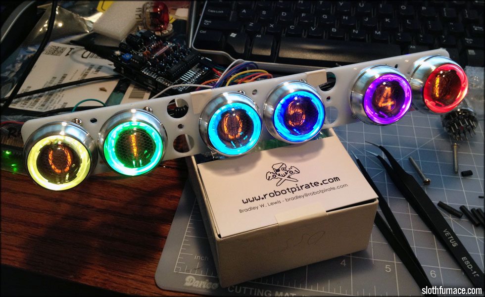 http://youtu.be/J8i86YIZoGc My plan is to use the electric imp to ping the current local weather and have my neopixel backlights display something according to weather conditions. So random blue flashes that ripple out if it's rainy, yellow if it's sunny, etc. right now I just have the neopixels doing lightly edited strandtest and knight rider Larson scanner action. http://youtu.be/rVtif8boQBk
|
|
#
?
Jan 17, 2015 03:05
|
|

|
Gorgeous.
|
|
#
?
Jan 17, 2015 03:09
|
|
|
Bad Munki posted:Gorgeous. Hey thanks, I suppose if I can't pull off the code to make the weather station functional, it will at least be pretty... Here's a vid of the rain with intermittent lightning mode... http://youtu.be/ok5sPjbiphU
|
|
#
?
Jan 17, 2015 17:04
|
|
|
That is amazing.
|
|
#
?
Jan 17, 2015 17:54
|
|

|
I have been thinking of some projects lately that need a ton of GPIO pins, so I spent some of the day today working on this board. This will give me 128 digital pins to mess around with, while remaining Arduino IDE compatible, and not requiring me to use a shield or anything. The design will change before I have them made, because I made some stupid decisions in the middle of the game here. I'll chuck the board and schematic files up on github when I'm done.
|
|
#
?
Jan 20, 2015 02:17
|
|

|
I assume that's the MCU on the bottom with a bunch of multiplexers above? Is that a 32U4 or something else entirely?
|
|
#
?
Jan 20, 2015 13:14
|
|


|
SoundMonkey posted:I assume that's the MCU on the bottom with a bunch of multiplexers above? Is that a 32U4 or something else entirely? 328 at the bottom (uno) and some MCP23017 chips up top, they're i2c IO expanders.
|
|
#
?
Jan 20, 2015 13:50
|
|
|
UberVexer posted:328 at the bottom (uno) and some MCP23017 chips up top, they're i2c IO expanders. Ah, I was just like "Oh I bet he's being fancy and using a 32U4" and the pin count looked about right 
|
|
#
?
Jan 21, 2015 00:05
|
|
|
SoundMonkey posted:Ah, I was just like "Oh I bet he's being fancy and using a 32U4" and the pin count looked about right I think the footprint is the same for the SMT 328 and the 32U4, but the pinout is different. USB isn't that important to me for this board, but maybe I'll do that and try to sell a couple of them in the mart or tindie or whatever. UberVexer fucked around with this message at 01:26 on Jan 21, 2015 |
|
#
?
Jan 21, 2015 01:23
|
|
|
I gotta admit I'm kinda tempted by this. http://www.ebay.com/itm/ESP8266-Serial-WIFI-Wireless-Transceiver-Module-Send-Receive-LWIP-AP-STA-/201205524305?pt=LH_DefaultDomain_0 ...despite likely issues being: - the range is probably trash - there's almost no documentation - what little documentation there is is poorly translated - setting up the wireless security is probably beyond tedious - relatively high power usage apparently (which is to be expected i guess) But still, $3 wifi module...
|
|
#
?
Jan 21, 2015 03:12
|
|
|
SoundMonkey posted:- there's almost no documentation Sometime when I was first playing with wifi, I ended up with a "Wifly" module, the docs were terrible at the time, and it discouraged me from finishing that project. If you end up with that chip, post your experience.
|
|
#
?
Jan 21, 2015 03:37
|
|
|
UberVexer posted:Sometime when I was first playing with wifi, I ended up with a "Wifly" module, the docs were terrible at the time, and it discouraged me from finishing that project. It's really tempting when I have this 2560 sitting here with all those drat UARTs I never use for anything. Hell with it, I'll order a couple and a level converter, then try to find a 3.3V supply somewhere. I don't have high hopes, but hey, $3.15. e: why must the only 3.3V boards I have be MSP430s and some Stellaris filth that I have no idea how to use.
|
|
#
?
Jan 21, 2015 03:46
|
|
|
Hackaday has a lot of posts on the ESP8266: http://hackaday.com/tag/esp8266/
|
|
#
?
Jan 21, 2015 03:50
|
|
|
mod sassinator posted:Hackaday has a lot of posts on the ESP8266: http://hackaday.com/tag/esp8266/ oh hell yes
|
|
#
?
Jan 21, 2015 05:45
|
|
|
https://www.tindie.com/products/AtomSoft/esp8266-buddy/?utm_source=twitter&utm_medium=twitter&utm_campaign=new_product_tweets This just popped up on my Twitter feed. Maybe I'll pickup one of those cheap ones from eBay. Edit: Some poking around on hackaday got me this. There's a whole bunch of documentation floating around for this thing I guess. https://github.com/bafeigum/ESP8266-Library http://hackaday.io/project/2879-esp8266-wifi-module-library UberVexer fucked around with this message at 17:07 on Jan 21, 2015 |
|
#
?
Jan 21, 2015 07:20
|
|
|
Yup, bought a couple of those after watching this; https://www.youtube.com/watch?v=rVbnnEMDSvU
|
|
#
?
Jan 21, 2015 22:48
|
|


|
This guy sells the whole programming kit pre-made for $10 shipped ($9.81 or something) on ebay, ships from USA even http://www.ebay.com/itm/281519483801 edit: Apparently you can   http://nathan.chantrell.net/20141230/wifi-mqtt-display-with-the-esp8266/ Hadlock fucked around with this message at 02:53 on Jan 22, 2015 |
|
#
?
Jan 22, 2015 02:48
|
|


|
|
| # ? May 28, 2024 13:25 |
|
|
I would like something similar, but just a simple wireless signal instead of wi-fi. What should I be looking for?
|
|
#
?
Jan 22, 2015 02:53
|
|