|
XBee modems are nice for small wireless serial communication: http://examples.digi.com/ They're a mesh network so you don't need a main router or anything else, just two modems to talk to each other.
|
 #
?
Jan 22, 2015 03:19
#
?
Jan 22, 2015 03:19
|
|

|

|
| # ? May 28, 2024 08:52 |
|
|
You can pick up an HC-06 bluetooth module which can run as master or slave, is 3-5v tolerant. The HC-05 is the same hardware but the firmware only allows slave mode (and typically a dollar cheaper). If you're patient you can reflash an HC-05 to HC-06.
|
|
#
?
Jan 22, 2015 03:27
|
|


|
Parts Kit posted:I would like something similar, but just a simple wireless signal instead of wi-fi. What should I be looking for? There's also http://playground.arduino.cc/InterfacingWithHardware/Nrf24L01 which can be had for pretty dang cheap, like well under a buck a piece, that may meet your more simple raw transceiver type needs.
|
|
#
?
Jan 22, 2015 03:33
|
|


|
Bad Munki posted:There's also http://playground.arduino.cc/InterfacingWithHardware/Nrf24L01 which can be had for pretty dang cheap, like well under a buck a piece, that may meet your more simple raw transceiver type needs. Yeah, you can buy 10-packs of Nordic boards on eBay for cheap, and probably 2 won't work, but it's still a hell of a lot better value than SparkFun or whatever. Try to get the + version if you can, there's some pretty cool additional features. Also just ordered a couple of those wifi modules since I totally forgot I had this adjustable buck regulator lying around unused, now I just have to work out the most effort-free way to deal with logic level conversion. Or I could just blow ten bucks on an Arduino board that uses 3.3V logic. For whatever reason I thought the Mega2560 did, but I was probably thinking of the Due.
|
|
#
?
Jan 22, 2015 04:27
|
|


|
Yeah the Due does 3.3V, but honestly I would avoid the board. It's fast and has a lot of memory, but not a lot of libraries support it and it has a lot of quirks. Just pick up a level converter chip and use that to do 5V to 3.3V (you don't need to worry about 3.3V to 5V since the signal will still register as high on a 5V Arduino).
|
|
#
?
Jan 22, 2015 06:58
|
|
|
AliExpress has these guys for $3.84 shipped with a more traditional Arduino-style pinout, has both a built in antenna and a standard-looking (MMCXJ-W?) connector with external antenna. http://www.aliexpress.com/item/ESP8266-Serial-Port-WIFI-Wireless-Transceiver-Send-Receive-Module-IO-Lead-Out/32254810086.html  Pin numbers are face down 
|
|
#
?
Jan 22, 2015 10:48
|
|
|
Hadlock posted:AliExpress has these guys for $3.84 shipped with a more traditional Arduino-style pinout, has both a built in antenna and a standard-looking (MMCXJ-W?) connector with external antenna. drat! looks neat, and not much more expensive.
|
|
#
?
Jan 22, 2015 12:41
|
|


|
I hope you can solder that serial header on yourself. They put it on the wrong way in that photo so you can't actually plug it into a breadboard. If it was facing up you could put it on a breadboard and then plug cables into it from the top.
|
|
#
?
Jan 22, 2015 20:17
|
|
|
eh, just grab some pliers and bend the pins 90 degrees
|
|
#
?
Jan 22, 2015 21:34
|
|


|
peepsalot posted:eh, just grab some pliers and bend the pins 90 degrees You should feel honored now. Question about programming with an external programmer: I think I've accidentally set lock bits that lock me out of using an ISP, is there a way to fix that?
|
|
#
?
Jan 24, 2015 08:19
|
|

|
Woo! Using the neopixel weather station instructable, http://www.instructables.com/id/NeoWeather-Ambient-Weather-Indicator/ I was able to get my Electric Imp hooked up to my wireless, which pings Weather Underground, and will feed my neopixel backlights different graphical representations of the current local ambient weather conditions... 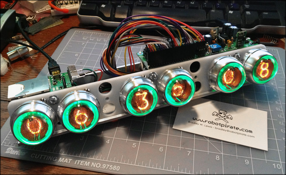 Since the photo, I went ahead and wired the electric imp board to 5V and GND coming off the nixie driver board. I might go in and make some new states, like sunrise, sunset, etc. But for now it's working. I spent all day friday with it going at work, while rain was happening outside off and on, and it reacted the way I expected. Faded in and out depending on weather. https://www.youtube.com/watch?v=XaQ3XCXqKm0 Now I need to build a nice box for it. I also switched the nixie driver board to a german one from my ArduiNIX because of size. This board is a lot skinnier, and will fit my project better. Plus I don't need this one to be reprogrammable, I just want clock functions for the nixies.
|
|
#
?
Jan 25, 2015 02:39
|
|

|
nonentity posted:[words and photo] That project is really coming along nicely. Maybe I'll make one eventually.
|
|
#
?
Jan 25, 2015 03:12
|
|
|
Is there any particular type of motor I should get if I want to have a very accurate angular velocity around 1500rpm? I'm trying to measure the speed of light via the Foucault method (http://en.wikipedia.org/wiki/Fizeau%E2%80%93Foucault_apparatus), but I'm not exactly sure what kind of motor I need to get that will give me a constant, accurate speed. I was looking at something like this http://www.adafruit.com/products/711. I'm probably going to be using a raspberry pi to drive it just because I already have one, but I could do it with an arduino so I thought you guys might be able to help.
|
|
#
?
Jan 25, 2015 18:56
|
|
|
TheCobraEffect posted:Is there any particular type of motor I should get if I want to have a very accurate angular velocity around 1500rpm? The two most common systems I've seen for regulating the speed of optical choppers / flicker veins / (whatever preferred term) have both been basically identical in function. Either a magnet and a detector are disturbed by a metallic blade or an IR beam and detector (which I'd recommend) are disturbed by an opaque beam to provide pulses to be interpreted by a dedicated uC. This is then used to either increase or decrease the current running to the motor to constantly adjust it toward the intended speed. If you can get the sensor to trigger the high and low states depending on the position of the blade, and set a uC to grab the system time on a rising or falling edge (or just on a change, if that's practical), you can have it difference the current value from the previous value, to figure out what the period is and adjust the current to the motor to get it in line with the intended period.
|
|
#
?
Jan 25, 2015 20:09
|
|
|
Two questions: 1) What is the maximum switching frequency of the Uno outputs? 2) What is the maximum switching frequency of this optoisolator: https://www.sparkfun.com/products/314 Background: Basically, I'm trying to build a stepper motor control circuit. Right now I have the arduino outputs going through the above optoisolator. There's no motor attached right now, I just have some LEDs on there...eventually I will be putting MOSFETs on there to drive the motor. I can sketch a schematic and post the code tonight after I get home, if necessary. The other thing I have hooked up for testing purposes is a pot to adjust the speed. Every 1000 us I'm reading the pot value and calculating the speed of the "motor" and translating that to us per step. I don't THINK there's a problem with my code, but I recently re-wrote it to run functions periodically off a timer instead of using the delay() function. So the loop() function freewheels and calls the functions every so often. I may have some bugs in there, but aside from hitting some top speed everything appears to be running as intended. Problem: I set up the serial to output the calculations to my PC. I can't remember the exact numbers I got last night, but at any faster than 20,000 us between steps I didn't see any visual difference in the blink rate of the LEDs. However, loop() was executing in about 600 us start to finish, so I don't think that was the limitation. Basically, I can still see them blink, but even if I scale the pot such that I achieve speed of 150 us between steps, it looks exactly the same to me. I would expect some visual difference at even 10,000 us/step vs 20,000 us/step, but it looks exactly the same to me. I haven't read an IC data sheet or really done any board level stuff since I was in college, but it appears that the optoisolator should be able to do either 80kHz or 36 us between switching (18 us each for rise and fall time, which looks like 27.7 kHz). edit: did a quick check of the data sheet and with the load resistance of 300 ohms for the LED, the minimum width of the output pulse (rise time + fall time + propagation delay (rise and fall)) for a 300 ohm load is about 18 us TOTAL, which gives me a max frequency of 55,648 kHz...way faster than I need. Still not sure if I'm reading this right, but from what I can tell the output response of the optoisolator isn't my limiting factor. So it could be the input characteristics, or the arduino outputs, or it could be the code. To be sure, I didn't really try hard to design the circuit...I just threw some stuff together and it works so far, but if I need to do some optimization then so be it. So far, the only software limitation that I can see is the loop() execution time, and that shouldn't be an issue at 20,000 us/step. Any thoughts as to where I'm hitting a limitation? Do my resistor values play a role in the switching speed? I know there's some RC garbage going on that will affect the rise/fall times, but I don't know if that's going to have a significant effect at the speeds I'm looking at. I'm not using the 50 ohm resistor on the input side as shown in the example schematic for the optoisolator. More something around 220-300 (can't remember exactly) in order to limit the current coming from the Arduino pins. But I am using the 100 ohm pull-down resistor on the output side of the optoisolator, as well as a 300 ohm current limiting resistor to power the LED. Also, does the current on the input side of the optoisolator have any impact on the output? I think I had intentionally selected the resistor as 220 ohm to limit the current supplied by the board. Do I need to up this to get better performance? Oh and for reference, everything is running on 5VDC. I have an ancient scope at home that I can hook up to try and get an actual read on the switching time...it's an old analog scope, so it'll be a chore, but I can probably get a ballpark. DaveSauce fucked around with this message at 19:52 on Jan 29, 2015 |
|
#
?
Jan 29, 2015 17:12
|
|

|
It would be helpful if you posted your code, but in my experience any time someone complains about having trouble at only high frequencies it is almost always because they are calling the serial write function every loop and it's bogging things down.
|
|
#
?
Jan 29, 2015 23:49
|
|
|
TheLastManStanding posted:It would be helpful if you posted your code, but in my experience any time someone complains about having trouble at only high frequencies it is almost always because they are calling the serial write function every loop and it's bogging things down. Welp. That did it. I had the serial spitting out the calculations every loop...I didn't have that in a separate function call. Oops. edit: OK so how do I speed up the serial write? Do I need to write my own driver? I'll eventually need to use serial to communicate with a PC for control. I parted the serial writes in to a diagnostic routine that runs once a second. Once I did that, typical scans went pretty fast at about 60 us. But, I timed the diagnostic routine on its own and it takes quite a while. At 9600 baud it was taking about 45,000 us, and when I crank it up to 115,200 baud it still takes about 4,000 us. Huge improvement, but it effectively means that if I ever want serial communication, I can't step any faster than 250 Hz. Any faster and I risk stuttering on the scans that I do a serial write. I'm not 100% sure if this is a problem, because I haven't bothered to calculate the speed I actually need, but it seems awfully inconvenient. DaveSauce fucked around with this message at 04:37 on Jan 30, 2015 |
|
#
?
Jan 30, 2015 03:24
|
|
|
DaveSauce posted:Two questions: I know it's been solved but but the answer is incredibly fast. It's limited by code, not the electronics. It's not hard to get it up to 4mhz but it requires a few tricks. It also can't do anything else at the same time, as it's a loop that's nothing more than turning a bank of pins on then off with interrupts disabled. Last I checked if you used standard digitalWrite calls it was closer to 100khz, but that was quite some time ago and libraries might have changed.
|
|
#
?
Jan 30, 2015 04:43
|
|

|
So I got one of those $10, 3 wheeled robot chassis off of ali express/ebay, am I just a huge baby for not soldering a wire to the leads on the motors, power switch and battery case? I soldered on 0.1" header pins to each of them to make it easier to plug a bunch of female to male jumper cables between them and a breadboard. Also, all the adafruit shield/hats have these big 10x15 "prototype areas" to fill up unused space, should I be using these for something? The only thing I can think of (right now) for my proto area is to add some 0.1" headers and a resistor inline to make it easy to add on extra LEDs for "tailights/headlights" off of the 3.3v rail. I feel like I'm wasting the space, but I'm thinking it's just probably a perk offered by a high quality PCB to justify Adafruit's higher prices.
|
|
#
?
Jan 30, 2015 06:51
|
|
|
DaveSauce posted:OK so how do I speed up the serial write? Do I need to write my own driver? I'll eventually need to use serial to communicate with a PC for control.
|
|
#
?
Jan 30, 2015 07:59
|
|

|
DaveSauce posted:OK so how do I speed up the serial write? Do I need to write my own driver? I'll eventually need to use serial to communicate with a PC for control.
|
|
#
?
Jan 30, 2015 08:42
|
|
|
TheLastManStanding posted:Post your code, because that still seems really slow. I'll post it tonight when I get home...at work right now, so I don't have it with me. I will also preface by saying it's been years since I did any C programming, so I'm still re-learning everything I've forgotten...meaning it's ugly and there's a lot of half-assed garbage in there. Other than that, I should clarify that I'm using Serial.print() and Serial.println(). I can't see from the reference that there's going to be a huge speed difference using Serial.write(), but I don't know what's going on under the hood. I'm also using the USB port, if that makes any difference. I did check, though, and it appears as though the Serial.print() command runs asynchronous. Doesn't that mean it should have very little impact on the main loop() execution time? I would take that to mean it simply parses and offloads the data to a buffer and returns while some other logic handles the nuts and bolts of sending the data over the wire. Unless I'm overloading the buffer and it has to sit and wait for the data to transmit out. But I'm making assumptions here to try and sound like I know what I'm talking about. On a similar-yet-separate subject, how accurate is the clock? I'm wondering if I can use it as a slip/stutter detection mechanism...meaning if I miss a step (or at a higher level, simply fail to run some arbitrary function) because something else took too long, I can detect this and correct. In the case of a stepper motor, I'm imaging that if I'm running the motor at a constant speed, and some long-running function causes me to miss a few steps, I can use the clock to estimate where I was supposed to be and run faster for a few cycles in order to correct myself. Basically, if this were a servo, I'd be trying to follow the position of a virtual axis. It's less of a constant-velocity application and more of a position-at-time application, if that makes any sense. That's a long way down the road from where I am now, but it's something I'm interested in attempting eventually. Also, odd question, but will the compiler complain if I try to assign negative values to an unsigned long? Similarly, if I try to compare an unsigned long to a negative value (say -1), will it work? I'm thinking about timers for my periodic functions. The timers will never actually be negative, but it would make my logic cleaner if I could treat 0 as run every loop, and -1 as never run (instead of run every 70 minutes). edit: So here's the code. Again, a lot of it is half-assed, and some of it wasn't well thought out...I just threw together what came to my head. stepperMotorStructs.h code:code:DaveSauce fucked around with this message at 18:46 on Jan 30, 2015 |
|
#
?
Jan 30, 2015 14:33
|
|
|
DaveSauce posted:On a similar-yet-separate subject, how accurate is the clock? Accuracy is decent, but not great. The best bit of data I can still find tested their resonator to be 761 PPM (or 0.077%). So it lost about a minute every day. I remember people talking about specs and saying it could gain or lose up to 5min every day, but I can't find any of those conversations anymore. That would be about ~3500ppm (.35%) Even if we take the worst of those figures, your 16mhz clock would be +/- 56000hz or slow/fast by 17uS/cycle. But this is comparing wrongness to an absolute clock. They produce wrong clocks, but typically they're consistently wrong clocks. The amount of wrongness will vary component to component, but it'll stay pretty much the same. Which means that I'd say it's very useable for things like this. DaveSauce posted:Also, odd question, but will the compiler complain if I try to assign negative values to an unsigned long? Similarly, if I try to compare an unsigned long to a negative value (say -1), will it work? I'm thinking about timers for my periodic functions. The timers will never actually be negative, but it would make my logic cleaner if I could treat 0 as run every loop, and -1 as never run (instead of run every 70 minutes). The compiler won't complain at all, and when you run it, it will be interpreted as a very large positive number. It works (almost)* like this. With signed integers if the first bit is 0 the number is positive, and if the first bit is 1 the number is negative. With unsigned ints the first bit is just the first bit of the number. So if you assign negative 2 (10000010) to an unsigned int you wind up with 130. This is probably not the behavior that you are looking for. There is no shortage of software that has problems related to this. *It's actually more complex than that. The real representation for a negative number is inverting the bits, and then adding 1. The reason for this is that it lets you use addition hardware for subtraction and gets rid of negative 0 (10000000). The actual representation for -2 is 1111 1110, which if assigned to a unsigned int would wind up as 254.
|
|
#
?
Jan 30, 2015 21:38
|
|
|
These should all be int since I can't image them going over 32,767 or 65,535.code:code:code:code:code:code:
|
|
#
?
Jan 30, 2015 23:00
|
|
|
To throw that all together with an example, the main part of your code should be something along the lines of:code:code:
|
|
#
?
Jan 31, 2015 00:48
|
|
|
DaveSauce posted:I did check, though, and it appears as though the Serial.print() command runs asynchronous. Doesn't that mean it should have very little impact on the main loop() execution time? I would take that to mean it simply parses and offloads the data to a buffer and returns while some other logic handles the nuts and bolts of sending the data over the wire. Unless I'm overloading the buffer and it has to sit and wait for the data to transmit out. But I'm making assumptions here to try and sound like I know what I'm talking about.
|
|
#
?
Jan 31, 2015 00:49
|
|
|
Aurium posted:Accuracy is decent, but not great. The best bit of data I can still find tested their resonator to be 761 PPM (or 0.077%). So it lost about a minute every day. I remember people talking about specs and saying it could gain or lose up to 5min every day, but I can't find any of those conversations anymore. That would be about ~3500ppm (.35%) It would probably work for my purposes then. I would prefer that it's accurate, but I can probably work around that if I have to. quote:
I should probably mention that I'm a computer engineer by training, so all this stuff is not completely foreign to me. But, I work in industrial controls, so the programming languages I work with are very different (though the underlying concepts are the same). I've worked with C before, but the last time I did anything was about 5 years ago, and that was just maintenance of someone else's code. The last time I had to write C code was in college. So I do understand 2's compliment, which is actually what I'm counting on. For my function timing logic, want to make a "run as fast as possible" condition (timer = 0), but I also want a "never run" condition (timer = max). I know that -1 is equal to all 1s in binary for a given variable size (i.e. int, long, etc.), so my logic would be much cleaner if I could just call "never run" -1 instead of loading 0xFFFF. There's no practical difference, in microseconds, between 0xFFFF and 0xFFFE for my purposes, so I'm more than willing to sacrifice 1us of timing to get cleaner code. Again, I just can't remember all the details of C, so I didn't know if the compiler would flip out if I tried to load -1 in to an unsigned long. TheLastManStanding posted:These should all be int since I can't image them going over 32,767 or 65,535. Yup. They were, until I had some wacky problems with my stepDelay calculation. stepDelay was an unsigned long, and my math was overflowing the ints so it was getting some weird results. I had had a few beers when I figured out what was going on, and I forgot that I could just cast them as unsigned longs in-line. I do intend on putting those back as ints. quote:
Yup. I noticed that a minute after I posted the code...I was hoping nobody would notice. Beer code is the best code. quote:For things like this: That briefly crossed my mind when I wrote it, but then I remembered that I always had trouble figuring out modulo stuff in college, so I decided to be lazy instead. quote:
So this appears to be the meat of the issue. I didn't suspect it would take that long. Not sure why...I guess I assumed that all the serial comms were handled elsewhere and wouldn't impact my code. quote:Your step function is basically returning a boolean (0 or -1), you might as well change it to one. Yeah, I made it return an int because I thought I might want to put some more information in there later, but meh. I'll probably make it a bool and then cross that bridge when I get to it. quote:You're also passing two global variables to it, which isn't necessary since nothing special happens in that function. Yeah, didn't really think of it that way. I wrote it that way to try to keep the loop() logic clean and to try to put as much other stuff in functions as I can. It was one of the first things I did in this program, so as I'm remembering how C works I'm probably going to change them. quote:But the main issue is that you're calling digitalWrite 4 times every loop when you should only be calling it once only when there is a need too (because digitalWrite is slow). The direction and the current step are enough to build a switch case which will run only when the current step changes. This also means the stepState array is redundant since the current step already contains that information (indirectly). It would also be beneficial to look into port manipulation as it would speed up your write times and simplify the output code. I was about to say that this is wrong, but it's not. I thought that was in my timed function. I'm also used to ladder logic, where if I'm not energizing an output every cycle it will turn off on its own...I know this is wrong in C, but my mind isn't fully in that mode. I'll probably just stash that logic up a few lines to where I increment stepState. I'll have to think about stepState some more. Eventually I will need to keep track of positional information, so I will need to have some way to track each step and add/subtract from some total number of steps. But thanks for taking a look at my code. I think I'll probably just plow forward knowing that I'll have to address the serial comms eventually. I'm not entirely sure what they will look like, so hopefully it isn't anything too hefty. Basically I'm going to be building a tracking mechanism for my telescope. The basic function is simply to control the speed at a certain rate, but in the future I will want to integrate it with PC-based (and eventually phone based) star-map software. There exists a serial protocol that will allow a PC to tell a telescope how to aim to any given star, so EVENTUALLY I'll be trying to figure that out. But for now, I just want to get the motor spinning, and have some fun playing with C code again in the meantime.
|
|
#
?
Jan 31, 2015 00:57
|
|
|
TheLastManStanding posted:To throw that all together with an example, the main part of your code should be something along the lines of: I found out that if I have something wired to pin 0, it won't upload the program. I was initially using 0-3, but it didn't take long for me to get tired of lifting the wire to upload. I didn't want to run in to any other weirdo issues, so I just used pins that looked to be bog standard pins. But that code looks a lot more straight forward. My mindset isn't quite in the realm of clever bit manipulation, so that chunk of code doesn't come naturally to me.
|
|
#
?
Jan 31, 2015 01:23
|
|
|
Pins 0 and 1 are shared with serial, so if you are using serial functions you (effectively) can't use them for anything else. I typically stick to pins 8 to 13 until I run out since that way I only have to dick around with one port register and I don't have to worry about screwing up the serial connection.
|
|
#
?
Jan 31, 2015 01:40
|
|
|
DaveSauce posted:It would probably work for my purposes then. I would prefer that it's accurate, but I can probably work around that if I have to. You can put a better tolerance 16mhz crystal on it. I've read about people also using a precision 32.768khz watch crystal. You could use a RTC. Or you could simply bench mark it over a day or so, and see how fast your board actually is, and have a calibration factor. It depends a bit on what kind of accuracy you're going for. DaveSauce posted:I should probably mention that I'm a computer engineer by training, so all this stuff is not completely foreign to me. But, I work in industrial controls, so the programming languages I work with are very different (though the underlying concepts are the same). I've worked with C before, but the last time I did anything was about 5 years ago, and that was just maintenance of someone else's code. The last time I had to write C code was in college. It won't complain, but you might have to have some fun with type casting to get your desired behavior. To me though, it seems less immediately obvious what would be going on while reading the code. So, excessively clever. I'm not sure exactly how you're counting, but it sounds kind of like you're pulling the result off the internal microsecond counter. So another thing you might want to be concerned with is that on the 16mhz boards, micros() has a resolution of 4 uS. So the return will always be a multiple of 4.
|
|
#
?
Jan 31, 2015 01:51
|
|
|
Hadlock posted:So I got one of those $10, 3 wheeled robot chassis off of ali express/ebay, am I just a huge baby for not soldering a wire to the leads on the motors, power switch and battery case? I soldered on 0.1" header pins to each of them to make it easier to plug a bunch of female to male jumper cables between them and a breadboard. As far as the free space on your shields - use it if it's convenient, or do something different if it's not. Totally up to you to decide what's going to work best. ")
|
|
#
?
Jan 31, 2015 03:49
|
|

|
code:The loop just moves a servo and then reads the distance from a distance sensor attached to it. It may be power? It may be that it's trying to push too much data per run of the loop? PRADA SLUT fucked around with this message at 08:46 on Jan 31, 2015 |
|
#
?
Jan 31, 2015 08:35
|
|

|
If you can get the servo to run at all, then power isn't the issue. Did you remember to start the serial connection in your setup? As side notes, the arduino clock only reads down to 4 micro seconds, so I don't know how reliable those delays between writes are. Are they for some kind of ultrasonic sensor? I'd also be concerned about incrementing i in steps of 50 when it's being used as an array index. I don't know if the arduino allots space for the whole array, but it would be better to play it safe and increment i by one and have a second variable that's equal to (ymin + i*50), such ascode:TheLastManStanding fucked around with this message at 09:37 on Jan 31, 2015 |
|
#
?
Jan 31, 2015 09:30
|
|
|
TheLastManStanding posted:If you can get the servo to run at all, then power isn't the issue. Did you remember to start the serial connection in your setup? As side notes, the arduino clock only reads down to 4 micro seconds, so I don't know how reliable those delays between writes are. Are they for some kind of ultrasonic sensor? I'd also be concerned about incrementing i in steps of 50 when it's being used as an array index. I don't know if the arduino allots space for the whole array, but it would be better to play it safe and increment i by one and have a second variable that's equal to (ymin + i*50), such as I thought it was just a problem with the loop, which is why I only posted it. It's actually a gigantic program (but under the sketch size limits). I now believe that it's actually a memory problem due to my arrays. My array is 1000 int's currently, which to my understanding is greater than the Arduino's RAM. I know how to slim it down, but before I do, is there a way to figure out how much memory various arrays take and what the Arduino can handle? So, if YMIN and YMAX represent the boundaries of my servo's movement. yrange is the difference between the two, and yDefault is an int array which holds all these data. Would my loop look like this then? (stripped-down code for length)) C++ code:PRADA SLUT fucked around with this message at 10:01 on Jan 31, 2015 |
|
#
?
Jan 31, 2015 09:45
|
|
|
PRADA SLUT posted:I thought it was just a problem with the loop, which is why I only posted it. It's actually a gigantic program (but under the sketch size limits). So the arduino has 2k of SRAM. This means all your variables have to be less than 2048 bytes. 1000 ints is 2000 bytes. Never ever ever use sparse arrays on an arduino. Try not to use floating point math, either, if you can help it. If you want it fast, precompute all the possible values you can. Historically you do all this stuff with #define to make it simpler since (presumably) none of this stuff changes. Saves some memory and can give some good optimization. C++ code:babyeatingpsychopath fucked around with this message at 14:31 on Jan 31, 2015 |
|
#
?
Jan 31, 2015 14:23
|
|


|
I'm starting a project to create a small arduino robot, and I have a few questions. 1. I'm thinking of using a DUE, but I'm finding stuff all over the internet about how the code doesn't work for it. I'm going to need to stack motor shields, because my design has 3 relatively high-powered motors, but I've come across a few indicators that the DUE doesn't support stacking motor shields. Is this true? If so, can I switch to an Arduino Mega 2560 and get stacking support? 2. Is it possible to control an arduino through an umbilical cord attached to a laptop but power it off of a battery? I don't want the laptop to supply any power to the robot. Or does the umbilical cord need to be attached to a controller of some sort? Globofglob fucked around with this message at 21:37 on Jan 31, 2015 |
|
#
?
Jan 31, 2015 21:13
|
|
|
Globofglob posted:I'm starting a project to create a small arduino robot, and I have a few questions. 1.) It depends on why it's broken. Some motor shields can't be stacked at all, which wouldn't be the due's fault. Libraries for the stack able ones might use Port manipulation commands that would need to be changed for the due. If you're decent at programming, you could probably fix or write your own library. Link what you're thinking of using if you want further opinions. 2. If you plug high enough voltage into the barrel jack/Vin it will automatically block power from the usb port.
|
|
#
?
Jan 31, 2015 21:45
|
|
|
PRADA SLUT posted:Is this on the right track? How do I initialize my array then? YMAX / INCREMENT? Would it be easier to make a quantized measurement and use that for everything (yrange / INCREMENT)? code:If you know your ymax/ymin/inc at compile time then you should use the code the other guy posted (though the range could also be defined). If you don't know what they are or if they might vary, then you should compute the largest possible array and use that. Currently your code only needs 20 slots in the array. TheLastManStanding fucked around with this message at 01:26 on Feb 2, 2015 |
|
#
?
Jan 31, 2015 22:01
|
|
|
I actually just started screwing around with the Adafruit motor shield v2.3 last night. It has a jumper that lets you power the Arduino off of the motor power supply, or off of Arduino internal power (i.e. USB umbilical cord). It supports a peak of 3A per shield which is a fair amount unless you're building an electric riding lawnmower, and stacks up to something like 32 high. I think they run about $19 shipped on ebay (which is cheaper than Adafruit direct).
|
|
#
?
Jan 31, 2015 22:05
|
|
|

|
| # ? May 28, 2024 08:52 |
|
|
Globofglob posted:I'm starting a project to create a small arduino robot, and I have a few questions. You could also use a separate motor controller that isn't a shield (these ones are pretty good), but it'll probably cost a bit more than the shields since you have 3 motors. You'd also need to write the code to send out serial motor speed commands, but that might be more straightforward than mucking around in someone else's code.
|
|
#
?
Jan 31, 2015 23:00
|
|