


|
Platystemon posted:You’ve modeled this correctly. If the contacts are really really dirty you’d get to the region to the right of the peak. Nothing would work, but nothing would melt, either. Melting happens when the contacts are the right amount of dirty to end up near that peak. Awesome, thanks for taking a look.
|
 #
?
May 23, 2017 20:44
#
?
May 23, 2017 20:44
|
|


|

|
| # ? Jun 4, 2024 21:08 |
|
|
If you have a perfect connection, then NONE of the power dissapation is at the connection, it's all in the load (making your pistons fire or lights turn on or whatever). If you have a crappy connection, a large fraction of the power dissapation is in the connection itself as heat (making it get hot/melty, which is bad), leaving less for the load (also bad).
|
|
#
?
May 23, 2017 20:59
|
|

|
Stabby McDamage posted:If you have a perfect connection, then NONE of the power dissapation is at the connection, it's all in the load (making your pistons fire or lights turn on or whatever). Yeah, even though you raised the entire system's resistance by 1 ohm (which probably doesn't matter *that* much), you've likely raised the resistance at that particular point from 0.001 ohm to 1 ohm which matters a hell of a lot more
|
|
#
?
May 23, 2017 21:00
|
|


|
Also I'm reading this guide to debouncing and found this very  quote: quote:quote:But some environments are notoriously noisy. Many years ago I put a system using several Z80s and a PDP-11 in a steel mill. A motor the size of a house drawing thousands of amps drove the production line. It reversed direction every few seconds. The noise generated by that changeover coupled everywhere, and destroyed everything electronic unless carefully protected. We optocoupled all cabling simply to keep the smoke inside the ICs, where it belongs. All digital inputs still looked like hash and needed an astonishing amount of debounce and signal conditioning.
|
|
#
?
May 23, 2017 21:08
|
|
|
ate all the Oreos posted:Yeah, even though you raised the entire system's resistance by 1 ohm (which probably doesn't matter *that* much), you've likely raised the resistance at that particular point from 0.001 ohm to 1 ohm which matters a hell of a lot more Or you could put it like that. If the resistance of the contacts is comparable to the resistance of your load, that�s usually bad. The interesting part is near x = 0.
|
|
#
?
May 23, 2017 22:33
|
|

|
Stabby McDamage posted:If you have a perfect connection, then NONE of the power dissapation is at the connection, it's all in the load (making your pistons fire or lights turn on or whatever). This is where I was having trouble, I was thinking on the extremes of the conditions (e.g. a 5k ohm resistor in series with the load), which would cause the current to drop so low it wouldn't be able to burn anything up. Also, sorry for cropping the X axis out, the peak occurs right at x=1.2. Gonna Send It fucked around with this message at 00:05 on May 24, 2017 |
|
#
?
May 24, 2017 00:03
|
|
|
Katosabi posted:Also, sorry for cropping the X axis out, the peak occurs right at x=1.2. As Jacobi�s Law dictates.
|
|
#
?
May 24, 2017 00:19
|
|
|
What's the best way to control a thermoelectric cooler with an Arduino? This would be for an air cooling application, specifically a beer fermenter to keep a chamber at around 65-75 deg F. Doing some reading, I've found a lot of contradictory information as far as control methods. Well, not really contradictory, so much as inconsistent. Most places agree that TECs don't like thermal cycling, but they all disagree about the frequency. Some say I can cycle as low as "10s of Hz" (specifically, 60Hz rectified without smoothing), other places say I need to PWM at 1k Hz or higher to avoid damaging the TEC. It seems like there's a "window" of control frequency that is off limits, but I can't figure out what it is. As an aside, I have no problem with a basic on/off thermostat style control, even though that's boring, but I've read that cycling even on the order of a couple minutes will still cause damage to the TEC over time...so I don't know if that should be like a 5 minute on/off cycle, or a 20 minute on/off cycle. So if straight PWM is out of the question, and thermostat cycling is out of the question, I'm assuming my next option is to just smooth out the PWM before it gets to the TEC, right? What is my best option to do this? I'm not strong with analog circuits...so do I just take a capacitor in parallel with the TEC and call it good? How do I size that cap? Follow-up, if I wanted to plant a thermistor in the heatsink fins to monitor its temperature, how do I adhere it? Are there special thermal adhesives I should use, or do I just use silicon caulk or something that will withstand the temp?
|
|
#
?
May 24, 2017 14:16
|
|

|
I've got kinda a weird issue about where to get odd parts. Specifically, my friend designed this peripheral she'd like to use with photoshop, basically just six mouse wheels in a row in a box, so she can map each one to a different keyboard shortcut (with the keyboard shortcuts controlling values like brush size, lightness, general photoshop stuff y'know). I also want the mouse wheels to be transleucent so I can light them with RGB LED's to indicate function or state or just make it look cool. For the prototype, I found this hilarious lovely mouse that Amazon's algorithms were trying to get rid of for really cheap: https://www.amazon.com/Cyber-CSLMSW01-7-Button-Scroll-Gaming/dp/B000MV2BC2 The wheel in it is actually pretty nice, it comes in its own little yoke thing that comes out as a complete module with the rotary encoder and can be mounted easily. Looks like I don't need to just waste the rest of the mouse either since they actually have a pretty nice little all in one laser / DSP module that spits out delta-X and delta-Y already pre-computed that I can definitely work into something else, by the way. Anyway, I was hoping to build two, meaning I'd need another six mice, but buying six at once made Amazon's algorithms decide that "oh poo poo they're in vogue again" and jack the price up to $10. Prices on ebay are around $8 so not much better. The price going up made me think I might be able to just get the mouse wheel elsewhere, but the very few "replacement mouse wheel" things I've seen on ebay are either $10 just for a drat wheel or not translucent. Is there even someplace I could go for such a weird part?
|
|
#
?
May 24, 2017 14:40
|
|
|
DaveSauce posted:Follow-up, if I wanted to plant a thermistor in the heatsink fins to monitor its temperature, how do I adhere it? Are there special thermal adhesives I should use, or do I just use silicon caulk or something that will withstand the temp? I feel I'm not qualified to answer about the peltier stuff since I've melted my last two peltier junctions I played with but as for thermistors, generally people just tape them to the surface using some kapton tape. You could also use thermal adhesive like this stuff: https://www.amazon.com/Arctic-Alumina-Thermal-Adhesive-5g/dp/B0009IQ1BU
|
|
#
?
May 24, 2017 14:42
|
|
|
DaveSauce posted:What's the best way to control a thermoelectric cooler with an Arduino? This would be for an air cooling application, specifically a beer fermenter to keep a chamber at around 65-75 deg F. I work with themoelectric devices for solid state cooling in the Aerospace industry. We've been using variable switch-mode power supplies to drive TEDs without issue. We've also driven them with PWM > 60kHz without any problems, but I haven't seen that tested anywhere close to rated MTBF hours. Thermal cycling will eventually kill the thing, though, whether it's induced by the driving frequency, mechanical mounting, or your heat exchanger. Eventually you'll just have to call the design good enough, and go for it. (oh, another gotcha, if your TED isn't sealed around the edges, any moisture that gets in there will kill the things.) For mounting a thermistor on the heatsink, just about any epoxy will do. You can get special thermal epoxies, but they aren't significantly better than the non-thermal epoxies. Mechanical mounting is always better, and you can buy some off-the-shelf thermistors that allow for this (http://www.ussensor.com/products/ntc-probes-and-assemblies/surface-temperature-sensing). The closer you can get to the TED, the better. We actually drill a hole in the side of the base of the heatsink, and epoxy the thermistors there.
|
|
#
?
May 24, 2017 15:47
|
|
|
ate all the Oreos posted:I've got kinda a weird issue about where to get odd parts. Specifically, my friend designed this peripheral she'd like to use with photoshop, basically just six mouse wheels in a row in a box, so she can map each one to a different keyboard shortcut (with the keyboard shortcuts controlling values like brush size, lightness, general photoshop stuff y'know). I also want the mouse wheels to be transleucent so I can light them with RGB LED's to indicate function or state or just make it look cool. For the prototype, I found this hilarious lovely mouse that Amazon's algorithms were trying to get rid of for really cheap: https://www.amazon.com/Cyber-CSLMSW01-7-Button-Scroll-Gaming/dp/B000MV2BC2 You should try meatspace stores. I bought a scroll-mouse for 3 dollars at Fry's once, and I'm sure the clearance section of any random electronics store will have a pile of lovely mice that they want to get rid of.
|
|
#
?
May 24, 2017 16:07
|
|

|
Corla Plankun posted:You should try meatspace stores. I bought a scroll-mouse for 3 dollars at Fry's once, and I'm sure the clearance section of any random electronics store will have a pile of lovely mice that they want to get rid of. Man I wish I had a Fry's around here  I guess that's the kind of thing Big Lots might have a bunch of... thanks! My other idea was to just make my own by molding them out of silicone or something, since you can buy the mouse wheel rotary encoders real cheap, but I prooobably can't make one that's any good myself 
|
|
#
?
May 24, 2017 16:19
|
|
|
ate all the Oreos posted:Man I wish I had a Fry's around here As with many small electronics, you can get mice from ebay for $0.99 shipped Like this for example, http://www.ebay.com/itm/371867513278 I ordered a few of this model a while ago (one to actually keep with my laptop bag, the others to hack on). Its pretty amazing what you can get for a dollar. Since its a mini mouse, the wheel is gonna be a little on the small side, not sure how much that matters to you.
|
|
#
?
May 24, 2017 16:50
|
|


|
peepsalot posted:As with many small electronics, you can get mice from ebay for $0.99 shipped Yeah I saw a bunch of 99 cent mice on ebay earlier but for some reason I couldn't find ones with glowing/translucent wheels, but now that I look again they're like all over the place. I'm not sure how I missed them... Anyway a mini mouse is probably fine, I'll order one and see. Thanks!
|
|
#
?
May 24, 2017 17:02
|
|
|
Or find the part number that you want and buy it from ebay, ali etc. Like these 5 encoders for 15 cents each: http://www.ebay.com/itm/5Pcs-of-11mm-Mouse-Encoder-Scroll-Wheel-Repair-Part-Switch-/142390551823?hash=item212723650f:g:2KIAAOSwlMFZH7iW. Basically you can find anything you want in China. You might need to provide your own LEDs.
|
|
#
?
May 24, 2017 17:11
|
|

|
Zuph posted:I work with themoelectric devices for solid state cooling in the Aerospace industry. We've been using variable switch-mode power supplies to drive TEDs without issue. We've also driven them with PWM > 60kHz without any problems, but I haven't seen that tested anywhere close to rated MTBF hours. Thermal cycling will eventually kill the thing, though, whether it's induced by the driving frequency, mechanical mounting, or your heat exchanger. Eventually you'll just have to call the design good enough, and go for it. (oh, another gotcha, if your TED isn't sealed around the edges, any moisture that gets in there will kill the things.) Thanks, that's helpful. I'm probably just going to design a cheap and dirty switched mode supply as the driver. Pretty sure 60 kHz is juuuust a bit beyond the capabilities of an Arduino...so hopefully I can get something smooth enough at a lower frequency.
|
|
#
?
May 24, 2017 21:56
|
|
|
You can easily achieve PWM rates of greater than 100KHz on an Arduino's ATMega328 if you program the chip at a lower level. Look up the output compare registers (OCRs) and the different available PWM modes. Instead of doing analogWrite(), you'll be toggling a pin based on the state of an internal hardware counter, which can be set to increment on every clock cycle. Increasing the rate beyond a certain point decreases the potential resolution, but that may be insignificant for your case. For instance, if you're okay with only having available duty cycles of (off the top of my head) 0%, 33%, 66% and 100%, you can do PWM at 4MHz with a 16-MHz chip.
|
|
#
?
May 25, 2017 01:01
|
|

|
The pwm hardware itself is good to 62.5khz (with the 16 MHz clock on the Arduino) without doing any low level programming at all, though you do need to paste in a function. https://playground.arduino.cc/Code/PwmFrequency It even uses the dedicated pwm hardware so it does it in the background and you can do other things, unlike if you had to bitbang pwm. This will also alter the timing of delay() and Mills() if you set it to 62.5khz using that function, they'll run about 62x faster as well. You have to account for that, but otherwise, you could just call that function, and then use analogWrite with no problem.
|
|
#
?
May 25, 2017 02:07
|
|

|
IIRC driving TECs with unfiltered PWM is slightly less efficient than driving them with the equivalent DC voltage. This may or may not matter for your application. Also doing a 100kHz+ half bridge or even simple open drain drive does warrant some design effort since actually switching a power FET cleanly at the required speed requires significant gate drive. Modifying a buck converter module to accept external voltage control is probably the fastest way to make an efficient driver circuit. longview fucked around with this message at 11:16 on May 25, 2017 |
|
#
?
May 25, 2017 11:12
|
|


|
Random question: I've been wondering why I don't see JFETs more often. MOSFETs are everywhere but JFETs only seem to be used in certain amplifiers or as inputs to op-amps. As far as I can tell they're "nicer" than MOSFETs at those jobs, so why aren't they used as ubiquitously as MOSFETs? Are they just more expensive to manufacture, or less able to handle high currents, or something like that?
Shame Boy fucked around with this message at 14:18 on May 25, 2017 |
|
#
?
May 25, 2017 14:15
|
|
|
ate all the Oreos posted:Random question: I've been wondering why I don't see JFETs more often. MOSFETs are everywhere but JFETs only seem to be used in certain amplifiers or as inputs to op-amps. As far as I can tell they're "nicer" than MOSFETs at those jobs, so why aren't they used as ubiquitously as MOSFETs? Are they just more expensive to manufacture, or less able to handle high currents, or something like that? Stolen from a website, not from my own knowledge, so I guess someone with better experience can confirm/deny but: Limitations of JFET: 1. FET�s theoretically are ideal voltage amplifiers with high input resistance and low output resistance. But it is seldom used in amplifier circuits due to its low gain bandwidth product compared to Bipolar Junction Transistors. 2. Faster switching times can be achieved in BJT compared to FET by preventing the devices from going into hard saturation. In FET internal junction capacitance�s are responsible for higher delay times. 3. The performance of FET deteriorates as frequency increases due to feedback by internal capacitance�s.
|
|
#
?
May 25, 2017 23:17
|
|


|
I believe MOSFETs are theoretically a little more efficient than JFETs because they have the insulation layer, and thus a reduced leakage current / increased input resistance. I dunno if that's enough of a deal to account for their ubiquity, though. Maybe they're just easier to manufacture.
|
|
#
?
May 26, 2017 00:45
|
|
|
I have an embarassing question. I have a spool of 22AWG, two-conductor, solid-core wire. It's the rip-apartable kind, like this: Except it's white and white-with-red-stripe and solid-core. Here's the problem: I want more of it, and I cannot for the life of me find where to get it. I don't care about color, I just want *any* solid-core rip-apartable two-conductor ~22AWG wire, because it's great for running power straight into a breadboard over distances (which I have a need to do). It's totally crazy -- I tried amazon, mcmaster, and digikey, and all the wire I find is jacketed instead of rip-apartable. Is there a specific term for rip-apartable wire I need to use? A better or more specific vendor? I'm shocked I can't pin this stuff down.
|
|
#
?
May 26, 2017 02:54
|
|
|
Try searching for speaker wire, zip cord, or auto zip wire. http://www.allelectronics.com/item/wrb-22/22-gauge-red/black-zip-cord/1.html
|
|
#
?
May 26, 2017 03:12
|
|
|
Solid-core wire of that type is gonna be a lot harder to find than stranded. Is there a reason beyond plugging it into breadboards that it has to be solid? Twisting and tinning the end of a stranded wire is all you usually need to do to make it breadboard-compatible.
|
|
#
?
May 26, 2017 03:31
|
|
|
ate all the Oreos posted:Random question: I've been wondering why I don't see JFETs more often. MOSFETs are everywhere but JFETs only seem to be used in certain amplifiers or as inputs to op-amps. As far as I can tell they're "nicer" than MOSFETs at those jobs, so why aren't they used as ubiquitously as MOSFETs? Are they just more expensive to manufacture, or less able to handle high currents, or something like that? Another major difference, not always a con, is that JFETs are depletion mode normally on devices (0 Vgs = ON). Its worth remembering that both JFETs and depletion mosfets are available with that feature if its needed. It makes this very simple current source among other useful things: 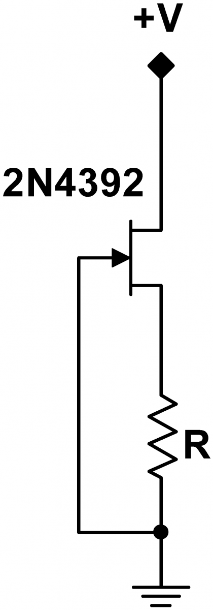
|
|
#
?
May 26, 2017 03:43
|
|

|
ate all the Oreos posted:I've got kinda a weird issue about where to get odd parts. Specifically, my friend designed this peripheral she'd like to use with photoshop, basically just six mouse wheels in a row in a box, so she can map each one to a different keyboard shortcut (with the keyboard shortcuts controlling values like brush size, lightness, general photoshop stuff y'know). I also want the mouse wheels to be transleucent so I can light them with RGB LED's to indicate function or state or just make it look cool. For the prototype, I found this hilarious lovely mouse that Amazon's algorithms were trying to get rid of for really cheap: https://www.amazon.com/Cyber-CSLMSW01-7-Button-Scroll-Gaming/dp/B000MV2BC2 1. 2 3 4 Pick whichever seller looks the most legit. There are probably more. this one has a neat looking wheel. Stuff is usually discounted a bit more if you order from within the app,
|
|
#
?
May 26, 2017 05:24
|
|

|
Sagebrush posted:Solid-core wire of that type is gonna be a lot harder to find than stranded. Is there a reason beyond plugging it into breadboards that it has to be solid? Twisting and tinning the end of a stranded wire is all you usually need to do to make it breadboard-compatible. I do robotics where there's a lot of spring-loaded "Weidmuller" wire connections, and tinning every wire would be annoying (especially since we *have* a spool of magic make-everything-good wire already, and just need more). Incidentally, nobody knows where the existing roll of solid zip cord is from...it just appeared in a box of junk one day years ago, and we've been living off of it ever since. Crotch Fruit posted:Try searching for speaker wire, zip cord, or auto zip wire. I think that particular link is stranded, but those search terms might help. Thanks! EDIT: I got it! The magic word is bell wire. Link. Looks like the kind of thing I'd best in person at a hardware store. Stabby McDamage fucked around with this message at 03:24 on May 27, 2017 |
|
#
?
May 27, 2017 03:17
|
|
|
Is there an accepted solution for storing data in a nonvolitile way when that data changes very often? I'm trying to implement an odometer. I'd like to store every 1/100 mile, so roughly 1 write per second at highway speeds. 100k write cycles until death means a cell "dies" that way about once a day. I've got some ideas, but I was wondering if this problem is already solved.
|
|
#
?
May 27, 2017 18:48
|
|


|
babyeatingpsychopath posted:Is there an accepted solution for storing data in a nonvolitile way when that data changes very often? I'm trying to implement an odometer. I'd like to store every 1/100 mile, so roughly 1 write per second at highway speeds. 100k write cycles until death means a cell "dies" that way about once a day. nvSRAM Data is normally held in SRAM, but when main power is removed, capacitance powers the chip for long enough to write to EEPROM. https://forums.somethingawful.com/newreply.php?action=newreply&postid=470634660 Platystemon fucked around with this message at 19:00 on May 27, 2017 |
|
#
?
May 27, 2017 18:55
|
|
|
babyeatingpsychopath posted:Is there an accepted solution for storing data in a nonvolitile way when that data changes very often? I'm trying to implement an odometer. I'd like to store every 1/100 mile, so roughly 1 write per second at highway speeds. 100k write cycles until death means a cell "dies" that way about once a day. I am solving the exact same problem (I'll bet you're doing this on a motorcycle too) and I am using EERAM, which is single-chip SRAM + EEPROM that uses a small external capacitor for auto-store on power down. http://www.microchip.com/design-centers/memory/serial-eeram You can also try to implement wear-leveling -- I think the math would work out.
|
|
#
?
May 27, 2017 19:06
|
|
|
Anyone ever solder onto circuit traces on kapton film? I would like some advice. I'm building a detector for my research project that involves a part made from framed sheets of kapton film with copper on both sides and lots of tiny holes etched in them. This part needs to be kept pretty clean to prevent arcing when a high voltage is placed across both sides, so I need to do the work in as clean an environment as possible (we don't have a clean room so I'm using some filtered air hood thing normally for biological work) and with gloves on, and have to clean the thing gently with compressed air, and that sort of thing. The part has a loose area with big fat traces that I guess you're supposed to solder wires onto, but it makes me a little squeamish because of how delicate the whole thing is. So I have a couple of questions. What's the procedure for soldering onto this stuff without wrecking it? Are there any kinds of removable connectors (some kind of clamp/clip type thing) that would be suitable for low current, high voltage (but under 1000 volts) work? Here's a picture of a ruined one that a researcher had a go at years ago. My boss thinks his soldering ruined it, but I also think unclean handling of it might have contributed to its failure (the holes in it are from me poking at it with calipers, but it was already hosed at that point.) New parts have a lot more length in the connection flap but like in the photo I'm going to have to trim it down so it isn't flopping and touching nearby circuit boards.  These dumb things are essentially hand made to order by CERN and gently caress if they put any documentation on the internet, at least in English. A drawing I found of it didn't even have the right dimensions for the screw hole placement, and the new ones have different size holes entirely.
|
|
#
?
May 28, 2017 03:46
|
|

|
I haven't soldered to anything quite like that, but if it's like soldering to those small flat kapton ribbon cables (looks like it is) then the secret is lots of flux, little bit of heat. Be quick about it.
|
|
#
?
May 28, 2017 04:26
|
|
|
Stabby McDamage posted:I do robotics where there's a lot of spring-loaded "Weidmuller" wire connections, and tinning every wire would be annoying (especially since we *have* a spool of magic make-everything-good wire already, and just need more). If you had to use stranded wire you would want to use ferrules on the ends instead of tinning them, it's faster and often has a small amount of strain relief built in. Weidm�ller makes a very nice stripper+ferrule crimper that has ferrules on a belt. For low cost stuff, Aliexpress has decent crimpers (Knipex knockoff) and good prices for bags of 1000 ferrules. BattleMaster posted:Anyone ever solder onto circuit traces on kapton film? I would like some advice. From the picture it looks like the biggest issue was using way too thick and stiff wiring, maybe try 22-24 AWG stranded wire with silicon insulation? It's usually much more flexible than standard PVC/Teflon insulated stuff.
|
|
#
?
May 28, 2017 14:39
|
|
|
BattleMaster posted:Anyone ever solder onto circuit traces on kapton film? I would like some advice. In addition to the above advice, make sure the copper is nice and clean and shiny before soldering. A regular pencil eraser is awesome for that stuff, cleans the oxidation right off without scratching the trace or the kapton.
|
|
#
?
May 28, 2017 18:20
|
|

|
longview posted:If you had to use stranded wire you would want to use ferrules on the ends instead of tinning them, it's faster and often has a small amount of strain relief built in. Weidm�ller makes a very nice stripper+ferrule crimper that has ferrules on a belt. I've tried ferrules before, and even with the fancy crimper, I got pull-out of the ferrule from the connector in enough cases that we just switched to using solid wire instead. Maybe I'm bad/dumb? Separate thing: I just snipped the leads from a 12V+5V power supply designed for use with computer stuff. It had black, red, and yellow wires. So far so good. Guess the pinout... ... Yellow = Ground. Black = 12V. Red = 5V. 
|
|
#
?
May 28, 2017 20:22
|
|
|
Stabby McDamage posted:Separate thing: I just snipped the leads from a 12V+5V power supply designed for use with computer stuff. It had black, red, and yellow wires. So far so good. Guess the pinout... The electrons don't care what color the insulation is. My entire wiring harness is done with white wire because I got an enormous amount for free. The wires are labelled on each end with masking tape. This sometimes comes off. Woe betide anyone that has to maintain anything I make, including myself.
|
|
#
?
May 28, 2017 21:25
|
|
|
Stabby McDamage posted:Separate thing: I just snipped the leads from a 12V+5V power supply designed for use with computer stuff. It had black, red, and yellow wires. So far so good. Guess the pinout... Dell was notorious for using non-standard and inconsistent coloring schemes. The lesson is, always check voltages on PSUs.
|
|
#
?
May 28, 2017 22:07
|
|

|

|
| # ? Jun 4, 2024 21:08 |
|
|
i'm a big fan of the "standard" on small wall-wart power supplies where the wire with the stripe is positive except when it's negative almost exactly 50% of the time. *borat voice* ....................NNNNNNNNNNNNNNNNNNNNNNNNNNNNNNNNNNNNOOOOOO-
|
|
#
?
May 29, 2017 00:53
|
|