


|
I have this weird old LCD from a radio and I want to make my own driver board. Plan is to make an interposer so I can at least measure the startup sequence and try to map that to a controller (probably 2xEpson SED1520). Based on the markings it was probably OEM'd by Philco, the part number 1223H1+DG suggests it may be 122x32 pixels (seem reasonable). Similar devices include this one: https://pacificdisplay.com/gdm/GDM-12232-10.pdf The non-globbed IC is a 74VHCT50 buffer which might be used to convert external 3.3 V logic control to 5 V. The little SOT-23 device is a voltage regulator. From an initial look I think the drive from the external processor is 3.3 V and the outputs from the LCD may be 5 V (probably going to 5 V tolerant inputs). 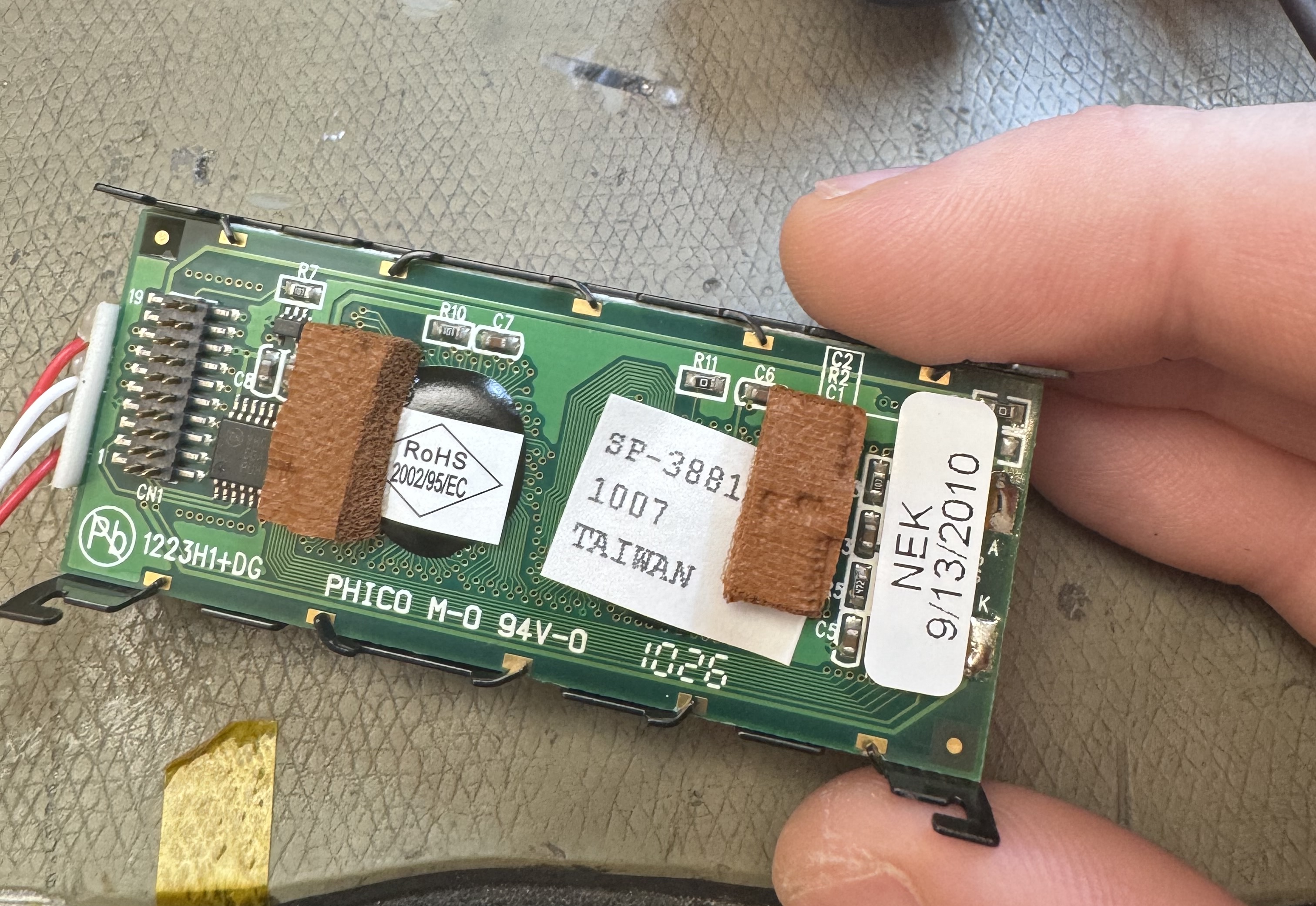 The part that is weird is those wires going off the side. I initially assumed it was the backlight, but the backlight is a green LED mounted in the module. From tracing and probing a bit: one of the red wires is connected directly to the incoming supply (9-36 V), the white one next to it is ground. The other set of red and white seems to be hanging off some kind of voltage control circuitry involving a bipolar transistor and a DAC line. So it's probably the LCD drive voltage that is normally generated on-board most modules, but it's weird how it seems to be largely insensitive to the supply voltage (no change to display contrast going from 9-24 V). I could probably trace the circuitry fully but the controller board has at least 4 layers so not entirely trivial. So, anyone familiar with old LCD's that use external LCD bias voltages and how those should be driven? E: I finally manned up and dismantled the LCD (and it seems even managed to reassemble it!) It looks like those wires are for two heaters? Presumably to make the LCD work in extreme low temperatures, neat solution. Not sure why my initial tests found that I had to have those wires plugged in to get an image, it works just fine without them now. Also it seems like the drive for these heaters is really complex for some reason, using a whole quad opamp just to run it. 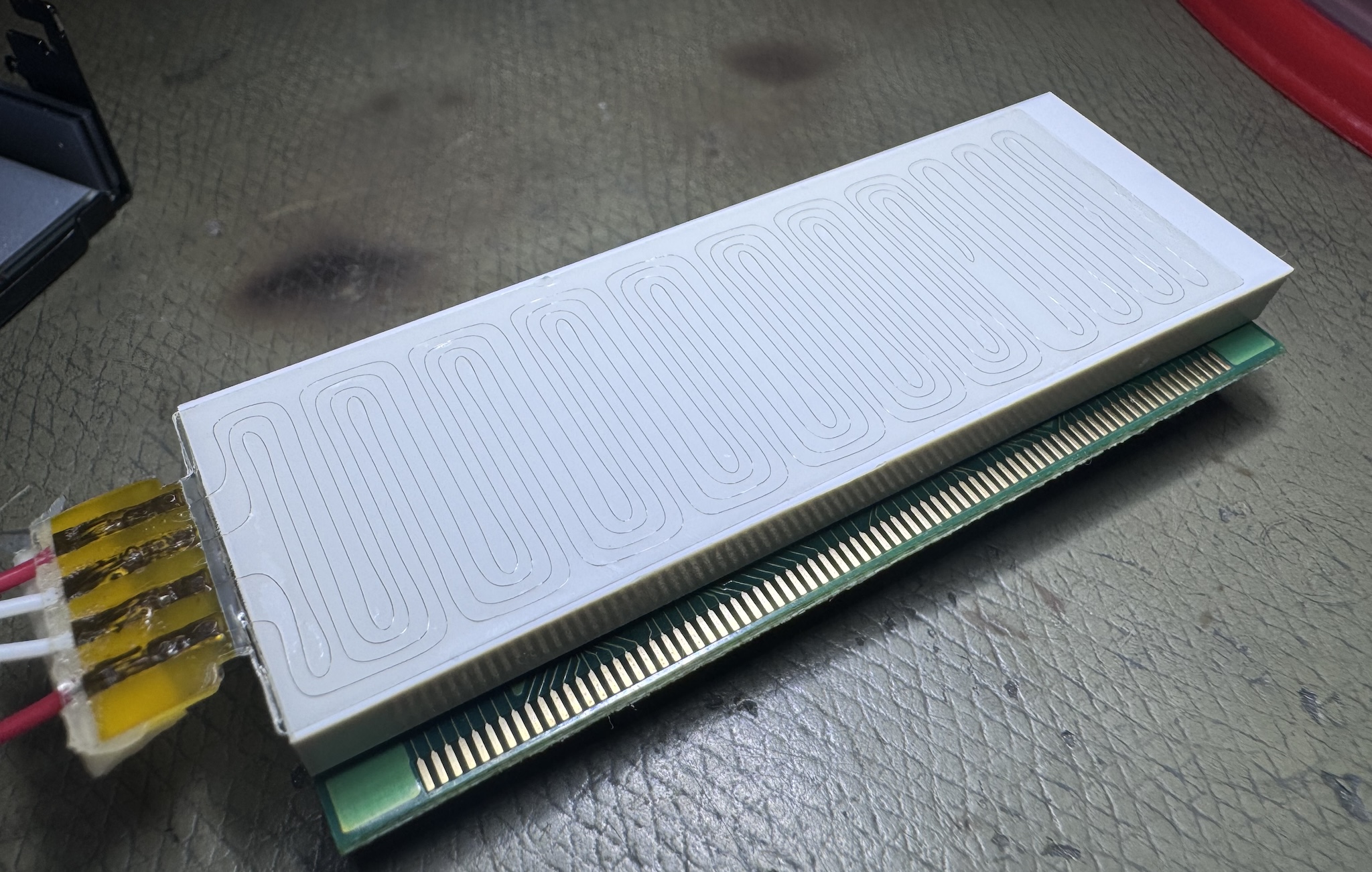
longview fucked around with this message at 15:38 on May 12, 2024 |
 #
?
May 12, 2024 12:26
#
?
May 12, 2024 12:26
|
|


|

|
| # ? May 30, 2024 09:06 |
|
|
I have found my favorite company name for test equipment: https://www.aliexpress.us/item/3256804251695398.html?gatewayAdapt=glo2usa4itemAdapt
|
|
#
?
May 14, 2024 01:56
|
|
|
I am trying to figure out how a common industry practice in warning lights work. "All" of them output and receive a sync signal on a single wire. I've put an oscilloscope to it, and while the devices are 12V fed, the sync wire outputs a roughly 5V square. I don't know if they all implement it the same, but for now I'm trying to figure out how it works at all. The signal is just a 5V pulse/square wave, both devices put this out when probed individually. When you connect the sync wires, they start flashing in sync and there is a single signal. Now my question is how they achieve this. Are they just putting a microcontoller pin to the wire and doing carrier sensing to see if someone else is pulsing and if so switch to input? Like my best guess is: microcontroller A: Put out signal for 700ms Listen for signal for 700ms repeat microcontroller B: same as A, but sees a signal during the sensing period. Syncs to A, stops output until signal disappears. Do you think that's how it is done? And if so, is that safe/what kinda protection circuit would be used for that? The same pin is also connected to 12V to change settings of the devices.
|
|
#
?
May 19, 2024 23:55
|
|


|
Are you saying the same wire carries 5V and 12V signals?
|
|
#
?
May 20, 2024 00:16
|
|
|
Cojawfee posted:Are you saying the same wire carries 5V and 12V signals? Possibly, but that's not the function I'm trying to understand. It's used as a 12V input to the (local) microcontroller alongside the sync function.
|
|
#
?
May 20, 2024 01:52
|
|
|
I am also trying to implement optocouplers for the first time https://www.farnell.com/datasheets/73758.pdf I want to (directly) drive a 140 mW 12V relay with it, but I can't figure out the relation of Fig. 8 to VCE (sat) and VCEO. I think the limit might only apply to the saturation voltage, which should be 0,2V * 13mA and well within the dissipation limits. Or is it the voltage I am using across it, so 12V * 13 mA, which might still barely be OK, but is too close for comfort. I'm really getting lost between optocoupler specifics, general transistor knowledge and how all these things interact.
|
|
#
?
May 20, 2024 01:57
|
|
|
Vceo is the voltage across the phototransistor side that will damage it even it there's no current on the LED side. Vsat is the voltage drop across the phototransistor side if you're using it as a switch when it's "on". So if you use it to switch 12V your load sees 11.8V. The danger region in Fig 8 is more a place where the load current exceeds the capacity of the opto (at a given LED forward current) and this causes the voltage across the opto to rise to the point that it's dissipating significant power. The can happen if the LED forward current is too low for your load. It usually happens in the forward active operating region, not saturation, so Vsat is unrelated. Why isolate an already-isolated relay coil, though?
|
|
#
?
May 20, 2024 03:53
|
|

|
Stack Machine posted:Vceo is the voltage across the phototransistor side that will damage it even it there's no current on the LED side. Vsat is the voltage drop across the phototransistor side if you're using it as a switch when it's "on". So if you use it to switch 12V your load sees 11.8V. So is the driving factor the current and the VCE follows that? I just wasn't sure how to interpret the graph, as it shows a range of 9 Volts, which is a lot more than the saturation voltages. I guess this is irrelevant as I am designing the circuit to be either off or saturated? I am using the phototransistors to isolate the IO of my microcontroller from automotive DC to have some digital inputs and outputs. E: Ok I think I just realized that this isn't gonna work anyway, I think i mixed up some values when going from the calculation of the 12V > microcontroller input to microcontroller > 12V relay. I need a max of 14mA on the output for the relay. To achieve this even after the 50% degradation and generally assuming worst case, I should be driving the LED at 42mA nominal as far as I can tell. As I don't want to drive the micro pins at more than 20mA I'll have to add another transistor after the photocoupler I guess. Here's my math 
SEKCobra fucked around with this message at 10:10 on May 20, 2024 |
|
#
?
May 20, 2024 09:07
|
|
|
SEKCobra posted:So is the driving factor the current and the VCE follows that? I just wasn't sure how to interpret the graph, as it shows a range of 9 Volts, which is a lot more than the saturation voltages. I guess this is irrelevant as I am designing the circuit to be either off or saturated? That graph isn't too helpful if you're just using the opto as a switch. The big thing it hints is that your output current (Ic) has to be less than your input current (If) for it to work well as a switch, since the saturation current is approximately the same as the forward current. SEKCobra posted:I am using the phototransistors to isolate the IO of my microcontroller from automotive DC to have some digital inputs and outputs. I guess it makes sense if you already need the isolated outputs and want them to be compatible with relay coils. If they were on the same board and permanently connected, though, I'd ditch the opto. SEKCobra posted:E: You can connect the emitter of the opto to the base of an external 2n3904 or similar cheap BJT, tie the collectors together, and use the emitter of the external transistor. This gives you at least 10x the current driving capability but takes the voltage drop up to about a volt. You can also buy optocouplers with "darlington" output that already have extra transistor built in. You can also buy tiny solid-staye relays in optocoupler packages that are very slow (milliseconds to turn on/off) but handle much more current in either direction. Stack Machine fucked around with this message at 17:56 on May 20, 2024 |
|
#
?
May 20, 2024 14:44
|
|
|
I always wondered what color the LED is inside an optoisolator, even those I suppose it doesn't really matter.
|
|
#
?
May 20, 2024 16:48
|
|
|
octarine
|
|
#
?
May 20, 2024 16:50
|
|

|
ante posted:octarine Optoisolators are made from cats confirmed.
|
|
#
?
May 20, 2024 16:54
|
|
|
That one has a 1.3V forward voltage, so probably IR.
|
|
#
?
May 20, 2024 17:48
|
|
|
Who has the oldest test equipment here? I got a scope from the 50s that I use whenever I need XY mode.
|
|
#
?
May 20, 2024 18:05
|
|
|
Stack Machine posted:That graph isn't too helpful if you're just using the opto as a switch. The big thing it hints is that your output current (Ic) has to be less than your input current (If) for it to work well as a switch, since the saturation current is approximately the same as the forward current. Alright, thanks for the advise. I've built a lil proptotype using a PC817 and a BC547 transistor just to confirm everything and I'm able to switch the relay with the microcontroller output just fine now. How do i spec out the appropriate drive current? Do I just take my final target current and guesstimate the needed saturation input by using the hFE? So working back from that I just use whatever exceeds the needed value on the original input with some margin? Or is there a better way to calculate this?
|
|
#
?
May 20, 2024 19:31
|
|
|
SEKCobra posted:How do i spec out the appropriate drive current? Do I just take my final target current and guesstimate the needed saturation input by using the hFE? So working back from that I just use whatever exceeds the needed value on the original input with some margin? Or is there a better way to calculate this? You have the right idea. I like to way under-estimate hFE whenever I can for the sake of margin. ~100 is a typical value but I use 10 for design if possible. If, say, I have a 5V logic output and a 20mA load, I'll use a 2.2k resistor for the base. This isn't always possible because eventually you run into I/O current limits, but there isn't much of a penalty for overestimating gate drive.
|
|
#
?
May 20, 2024 21:01
|
|
|
Stack Machine posted:You have the right idea. I like to way under-estimate hFE whenever I can for the sake of margin. ~100 is a typical value but I use 10 for design if possible. If, say, I have a 5V logic output and a 20mA load, I'll use a 2.2k resistor for the base. This isn't always possible because eventually you run into I/O current limits, but there isn't much of a penalty for overestimating gate drive. The math ends up somewhere around 30 microamps for the transistor because it has a gain rating of like 400
|
|
#
?
May 20, 2024 21:55
|
|
|
I have a dumb idea but don't know where to go from here. I've got a sewing machine with a foot pedal that has an auto-thread cutting feature when you step backwards. It's really annoying to accidentally (which is easy) step backwards and have the thread cut in the middle of something important. There are workarounds for physically blocking that, but the caveats are too annoying for it to be great. It's just a 2 conductor barrel jack into the machine. Inside the pedal is a linear pot PCB with 3 pins, a resistor and a variable resistor. Mechanically, the pedal's zero position is the lower third on the pot. Probing the two wires, the neutral pedal position is about 2.5vdc, increasing (faster sewing) drops down to nearly zero volts. If it's pulled back past the neutral thread position to trigger thread cutting, it jumps up to 4.5v and stays there (triggering a single thread cut). I was really hoping to find 3 wires in the plug, because then I could presumably just interrupt one wire and have the feature be optional. With it being all based on one pot I don't really know where to go. My goal is to build something like an inline cord switch with male and female barrel jacks (plugs into the machine, pedal plugs into it) so that I don't do any actual modification to anything OEM. Is there an easy way to do something akin to a high pass filter but for voltage?    I'm sure I could cut a trace and attach a switch, but the goal is something that doesn't involve modifying anything if possible. Hypnolobster fucked around with this message at 23:17 on May 20, 2024 |
|
#
?
May 20, 2024 23:00
|
|


|
Add a ~4V zener diode and resistor in parallel. So anything above 4V will get chopped. Actually, you're more likely to have 2x red LEDs around. Do that, it's be around 3.4ish volts, and you'll have a nice indicator for whenever it saves your rear end Add a switch in series to that as well, so you can re-enable the cut feature
|
|
#
?
May 20, 2024 23:16
|
|
|
I just spend more time with a better setup trying to figure out what it's doing and it's a little different than I thought. Sewing speed control voltages are about 2.5-0v, but the neutral zero position is ~4.3v. Pulling back to trigger the thread cut is ~3.6v. My ability to understand circuits is rear end, but I think the zero position is machine voltage and the thread cut triggering is putting the resistor into the circuit. I think if I chop the voltage off anywhere above 2.5v it'll just never stop sewing or immediately thread cut. I could pop that resistor out and put a switch in series but that kills the dream of a plug and play fix. Hypnolobster fucked around with this message at 00:01 on May 21, 2024 |
|
#
?
May 20, 2024 23:54
|
|
|
Hypnolobster posted:I could pop that resistor out and put a switch in series but that kills the dream of a plug and play fix. How much does one of these pedals cost? How easy would it be to replace?
|
|
#
?
May 21, 2024 00:26
|
|
|
I mean, if you want a circuit board to do something different, you have three options: - Modify the PCB - Replace the PCB - Add some sort of interposer circuit after the fact. I'd rule this one out to being quite complicated - Like, 3 or 4 op amps, I guess. Which is not super hard if you're experienced, but it is a project on its own. If you snip one of the wires of the resistor and snake in a little switch on a jumper wire in series, then you have a very fixable bodge, if you decide to remove it later.
|
|
#
?
May 21, 2024 00:38
|
|
|
kid sinister posted:How much does one of these pedals cost? How easy would it be to replace? $100-$120, unfortunately. I think I'm going to just pop one leg of the resistor out and connect in a little switch through the side of the pedal. I was sort of hoping I could do something simple and non destructive to be able to sell a few to people on Etsy or something but that is definitely not worth it. Hypnolobster fucked around with this message at 00:47 on May 21, 2024 |
|
#
?
May 21, 2024 00:39
|
|
|
The niche Etsy market sometimes would be worth figuring out an interposer board and selling for a hundo each, but looking at it again, you'd need a separate power source and it just becomes finicky
|
|
#
?
May 21, 2024 01:14
|
|
|
Hypnolobster posted:$100-$120, unfortunately. How hard would it be to make one from scratch? The board doesn't appear to have any ICs. It should be fairly easy to remake from discrete components. I bet you could start with a DIY guitar pedal.
|
|
#
?
May 21, 2024 02:43
|
|
|
kid sinister posted:How hard would it be to make one from scratch? The board doesn't appear to have any ICs. It should be fairly easy to remake from discrete components. I bet you could start with a DIY guitar pedal. The carbon traces are not something I'd want to replicate
|
|
#
?
May 21, 2024 02:58
|
|
|
I wonder if you could put some kapton tape over the part of the trace that enables the thread cut.
|
|
#
?
May 21, 2024 03:15
|
|
|
Could you solve this mechanically by gluing in a little wooden block or something that prevents the pedal from moving backwards?
|
|
#
?
May 21, 2024 18:17
|
|


|
Sagebrush posted:Could you solve this mechanically by gluing in a little wooden block or something that prevents the pedal from moving backwards? OP said he didn't want to modify the existing pedal too much.
|
|
#
?
May 21, 2024 20:12
|
|
|
I'm fixing up a regulated power supply for amateur radio that belonged to a dead guy. I didn't realize until later on that the PCB has two potentiometers on it, which I might have jostled while scrubbing away decades of mouse poop. I'm guessing at least one of them controls the output voltage, but I figured I should ask for a second opinion. I can't find any circuit diagrams online for this thing so I'll have to map it out myself later, and I'll have the outputs connected to a multimeter the first time I power it on. While I'm in there I may as well replace the mains cord with an IEC connector to make it detachable. The original was a non-polarized two prong plug, so I'll cannibalize a C8 fitting from something at the recycling depot. I was thinking of adding a chassis ground, but I don't think there's room for a C14 fitting on the back plate and I don't know how much that might mess up its radio characteristics.  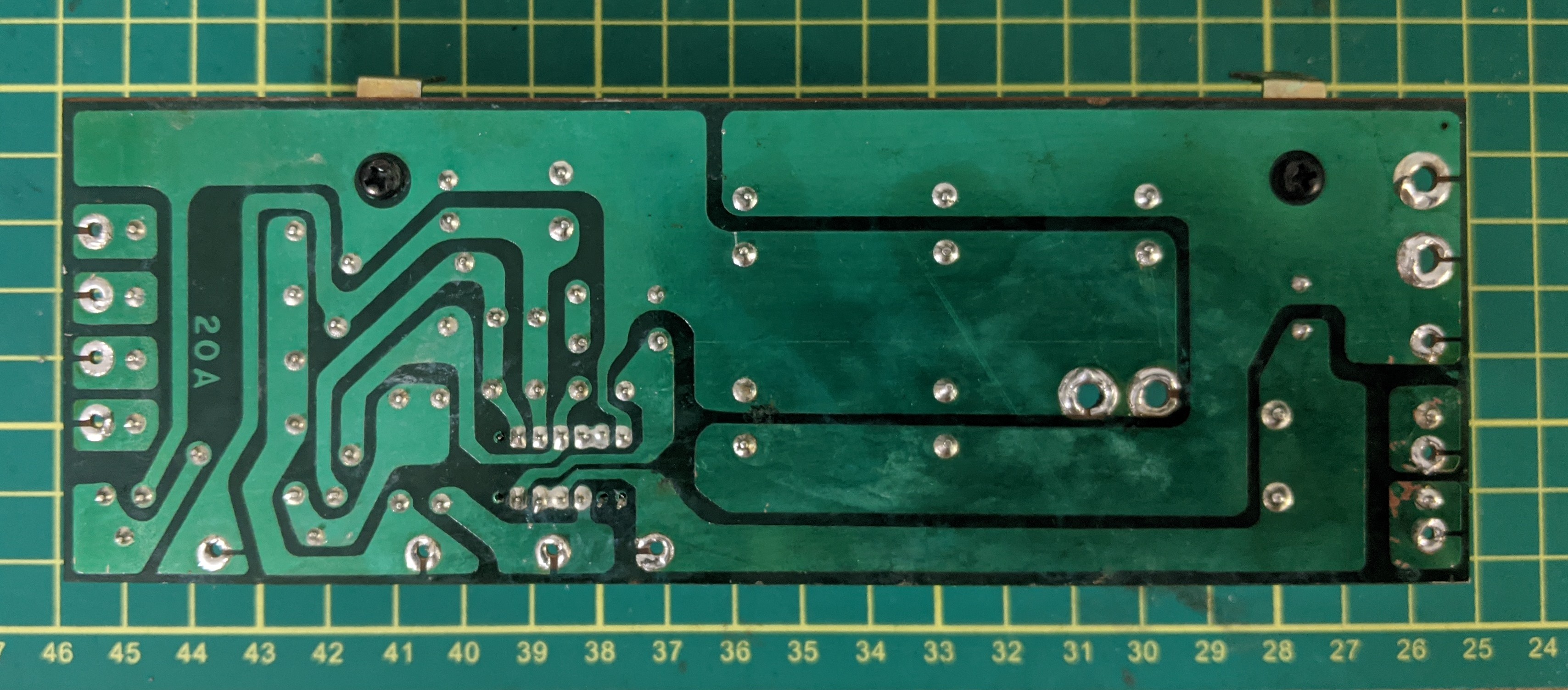 
|
|
#
?
May 23, 2024 16:51
|
|


|
Coxswain Balls posted:I'm fixing up a regulated power supply for amateur radio that belonged to a dead guy. I didn't realize until later on that the PCB has two potentiometers on it, which I might have jostled while scrubbing away decades of mouse poop. I'm guessing at least one of them controls the output voltage, but I figured I should ask for a second opinion. I can't find any circuit diagrams online for this thing so I'll have to map it out myself later, and I'll have the outputs connected to a multimeter the first time I power it on. Judging by a very cursory look at the tracks and the datasheet for that chip, the pot on the right (in that top picture) sets the voltage and the pot on the left sets the current limit.
|
|
#
?
May 23, 2024 17:31
|
|


|
Just like a proper benchtop power supply, I figured as much. Hopefully I didn't mess up the current one too bad, since my multimeter only goes up to 10A and I'm not sure what the smartest way of calibrating that is. My napkin math is: V = 13.8 V I = 20 A P = 276 W I'm thinking of wiring four of these up in parallel (plus one more 15W bulb) and turn the current knob until the whole shebang stops getting brighter/starts getting dimmer. I have a setup like that kicking around somewhere from working on quadcopters to prevent shorts in case of something being messed up, so the potential short just went through a bulb. It's also got a 20A fuse in there in case I really screw something up. Now that school's out for the summer I miss having access to a lab with proper testing equipment.
|
|
#
?
May 23, 2024 20:40
|
|
|
I have a 1997 Fadal CNC mill that has a proprietary keyboard/card. The keyboard card also takes inputs from a rotary mpg (prob an encoder) and various positional switches. I want to make an arduino or other microcontroller that can basically emulate/mitm this keyboard/pendant. The switches are easy but what�s the easiest way to figure out what protocol the keyboard is using. Pic, it�s on the bottom left. The keyboard is on the opposite side with the various switches and encoders connecting to it. 
|
|
#
?
May 24, 2024 04:10
|
|

|
I do IT work at a high school, and around February this year, I wanted to have a vintage computer in my office breezeway to show off to students. A friend had a Macintosh Classic that he was willing to loan me, but it wasn't playing any audio. A lack of audio is a usual sign of leaking capacitors on the logic board, and sure enough, they looked pretty goopy. In exchange for displaying the Mac Classic, I offered to fix the logic board. This was the first time I've tried to remove leaky caps, and while I have all of the fancy tools, I didn't do it well due to my inexperience. Multiple solder pads on the logic board, along with the bad capacitors, were pulled off. In hindsight, upping the temperature on my soldering tweezers higher than I'm used to with my normal soldering iron would have probably done the job.  I was not content with soldering bodge wires all over the board, so I did the next reasonable thing and replaced the logic board PCB entirely. As luck would have it, Kai Robinson has completely recreated the board and made it open-source. I sent the Gerber files to a PCB manufacturer and had them delivered within a week.  I knew my Radio Shack desoldering iron would not be up for this task, so I caved and bought a Hakko desoldering gun. The Hakko is incredible for through-hole chips and passives, but it put a dent in my wallet. For less delicate solder removal, the slingshot solder sucker that I got from a local surplus store also worked great.  I also picked up a hot air rework station to pull the surface-mounted chips and went to work. The first couple of chips were hard to pull off, but it was pretty quick work once I got into the rhythm.  Once I had all the components removed from the old board, it was time to prep the new board and receive them. I used a solder stencil and solder paste to apply the surface-mounted chips because I didn't trust my soldering skill on some of the SMD pitches. The stencil worked, but I think more paste was applied than desired due to the oversized stencil flexing while the paste was being applied. This resulted in some solder blobs, which caused shorts later. To liquify the solder, the board was baked in a toaster oven (not used for food).   I next turned my attention to the back of the logic board. I soldered over a hundred resistors and capacitors by hand, and it took a few hours to complete.   Finally, it was time to solder the thru-hole components back onto the board and power it up!  Uh-oh.....  This is where I learned that details online about the Mac Classic are a little fleeting. The logic board is effectively a cost-reduced version of the Macintosh SE, and so many issue details found online point to the SE rather than the Classic. For instance, the error that displays indicates a memory error, but it references bank B�something that makes sense for the removable memory in the Macintosh SE but not so much with the soldered memory chips on the Classic. After watching some Macintosh Classic Youtube videos from Adrian Black and going over the hand-drawn bomarc schematics, I came up with a continuity test game plan. Sure enough, a hidden solder blob was found under the memory chip marked 'UK7', shorting Vcc to the CAS pin. The chip was cleaned, resoldered to the board and....  Success! A few small things still needed to be addressed, like enlarging the vias to accept the RAM expansion socket and fixing an incorrect resistor value for the sound afterward. The Mac Classic now sits in the office breezeway, running a demo of Lode Runner from a BlueSCSI. A couple of students walked in and were in awe of such an 'ancient' computer. This was one of the largest electronics projects I have taken on, and it required all of my tools to complete. My confidence was middling on whether the Mac would boot again, and I am ecstatic that it is now fully functional again!
|
|
#
?
May 24, 2024 14:43
|
|

|
That looks awesome. Which hot air rework station is that? I picked up an Aoyue kit for my first soldering station ten years ago and it's still working like a champ. That one looks like it'll also last a while, unlike all the cheap Amazon models with the same handle construction.
|
|
#
?
May 24, 2024 15:04
|
|
|
Coxswain Balls posted:That looks awesome. Which hot air rework station is that? I picked up an Aoyue kit for my first soldering station ten years ago and it's still working like a champ. That one looks like it'll also last a while, unlike all the cheap Amazon models with the same handle construction. Years ago, I somehow got an Aoyue Int 2901 soldering iron from Sparkfun. While it's a little hard to get tips for it in the US, I really do enjoy using it. Because I was happy with my Aoyue soldering iron, I got the Aoyue 852A++ for $150. The hot air side seems to work pretty well, but the vacuum pump feature is criticized as a little weak, which I can agree with after testing, but it was serviceable.
|
|
#
?
May 24, 2024 15:34
|
|
|
Doesn't Aoyue just use Hakko tips, or is that only certain models? I've got a 937+ so I let myself be a little rough with them since I can get replacements at the local electronics shop.
|
|
#
?
May 24, 2024 15:57
|
|
|
CarForumPoster posted:I have a 1997 Fadal CNC mill that has a proprietary keyboard/card. The keyboard card also takes inputs from a rotary mpg (prob an encoder) and various positional switches. I think I'm on track to solve this. I can probably inject keyboard signals through the 16-pin J4 with an arduino mega and some level shifters to go 3.3V->5V. I cant find any signals being sent to the main PC board when its disconnected on the bench but simply injecting keystrokes with is really all I need. I put it on a scope and the key strokes are 250us lows with 5.5ms highs on two pins. One of the pins starts low the other starts high. CarForumPoster fucked around with this message at 22:00 on May 24, 2024 |
|
#
?
May 24, 2024 21:58
|
|
|
I hate old radios. Get this: there are actually rectifier tubes that can burn out if their pilot lamp burns out. Yes, you read that right. If a piddly little 75 cent bulb burns out, it can keep the entire device from working. Worse yet, an LED bulb isn't a direct swap in, because the draw will be different!
|
|
#
?
May 27, 2024 00:02
|
|
|

|
| # ? May 30, 2024 09:06 |
|
|
what about an LED in parallel with a big resistor? e: by big i mean a high power rating. probably a low resistance value
|
|
#
?
May 27, 2024 00:06
|
|