


|
scholzie posted:FYI, it's not Jairbrekr's gimmick. His are pretty good though. There was a whole thread dedicated to explaining things with foul language. You are most correct. It was the "Science with Swears!" thread, which had some awesome lessons in it. There is a special place in my heart for the "human being refraction" lesson I did, which is t otally off topic and not being posted here. So if anyone wants to follow suit, by all means please do so. This thread needs more sex and foul language, and my time is sadly limited right now. My job is keeping me quite busy (for a fabless chip company no less).
|
 #
?
Jan 15, 2008 04:55
#
?
Jan 15, 2008 04:55
|
|


|

|
| # ? May 21, 2024 18:50 |
|
|
There's actually a REALLY GOOD scanned copy of "Getting Started with Electronics" floating around on the intartubes that is easier to read than the printed paper copy - but if you find it, go buy the real thing from Amazon anyway, so that Forrest Mims gets his  . .I also recommend the United States Navy Electricity & Electronics Training Series (NEETS) - its a great tutorial, and free for download (PDFs). Electronics and kits are ADDICTIVE. I never thought I was good enough to use a soldering iron. This is how it went, approximately in order, from June to September 2005: (click for pictures) "Learn to Solder" kit, cheap soldering iron, blinky-LED bits Hacked my own CVS camcorder cable Sound detector, LED flasher "Traffic Light" LED - and my first IC socket! "Running Light" LED kit PONG! Active HF radio antenna kit - with custom power LED Scrolling Programmable LED Display Time to get a new soldering iron (Weller WTCPT, $30 on ebay) Ramsey SR2C Shortwave Radio Ten-Tec 1253 Regenerative Shortwave Radio (TONS of fun) Time to get hardcore - Southern Cross 1 Z80-based computer The masterpiece - Replica-1 Apple I clone (I also picked up a couple of microcontrollers to play with; a BASIC Stamp kit and an Atmel AVR Butterfly) There's nothing quite as fun as powering up a project when its done and hearing Radio Taiwan, or plugging in a keyboard and old monochrome monitor and programming in BASIC on a system that you built yourself from the ground up: 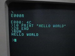 Since late '05, I've also built a couple of CMoy headphone amplifiers and a Linkwitz crossfeed box. I've had to temporarily give up my workbench (it also serves as the dining room table), but when I get it back I've got a P112 Z80 single-board computer kit in a box waiting to be touched in sensitive places with a hot metal stick. Edit: When it comes to solder, there is no god other than Kester, unless it is the false god of lead-free solder (which sucks to work with). In four months, I went from this (having never touched a soldering iron before): 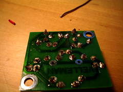 To this (GET YOURSELF A LIGHTED MAGNIFYING DESK LAMP AND DECENT SOLDERING IRON) - I did the two bottom rows and the vertical row on the right, of header pins: 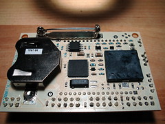
mrbill fucked around with this message at 05:48 on Jan 15, 2008 |
|
#
?
Jan 15, 2008 05:19
|
|

|
clredwolf posted:I think that's the purpose of having CE and EE separate, but it's not a great seperation if you ask me. Digital stuff is absolutely everywhere and everyone in EE needs at least a little exposure to digital technology at this point. From what I count though, here are the EE 'disciplines': CE is Civil Engineering, CompE/CmpE is Computer Engineering, EECE is Electrical and Computer Engineering (usually in the same department but different majors). The first thing anyone should know about digital electronics, is that it doesn't really exist. There is no such thing as a digital electronics engineer because anything digital is really just a bunch of analog poo poo that passes signals above and below a threshold. The faster the clock speed the more analog stuff you need to know. Splitting EE disciplines up wouldn't work. Everyone starts out taking the same courses: Physics, Calc (all of them), Chemistry, circuit theory, electronics, statistics, basic classes from Mechanical/Chemical/Industrial engieering, C programming then you specialize in one or two of those disciplines. As a BS student, one is plenty. You don't even start the specialty until the third year. Side note: If you're at all serious about getting started in electronics, you need this book: http://books.google.com/books?id=bk...-with-thumbnail It's incredible, has great examples, and some reference circuits you can just use straight from the book. It also helps you pick out the right parts for what you're doing, which may seem a bit mysterious at first. It explains some basic theory too, so you can use this one book as a starting point. I'll post a project I've done recently as soon as I can get the video up on Youtube.
|
|
#
?
Jan 15, 2008 06:29
|
|

|
900ftjesus posted:If you're at all serious about getting started in electronics, you need this book:  Horowitz and Hill Horowitz and Hill
|
|
#
?
Jan 15, 2008 06:36
|
|


|
900ftjesus posted:If you're at all serious about getting started in electronics, you need this book: I have it as well and it is a great book. Probably enough to get a taste since some of the standard devices are still the same. But the book is from 1989 so be prepared to have to modify what they tell you. I wish those fuckers would hurry up with 3rd ED.
|
|
#
?
Jan 15, 2008 06:37
|
|

|
Also recommended: Practical Electronics for Inventors. I have a copy, it rocks and has all the info I need for my basic / intermediate projects.
|
|
#
?
Jan 15, 2008 06:48
|
|
|
mrbill posted:Also recommended: Practical Electronics for Inventors. I have this too; it manages to be a general overview of many aspects while still having a lot of detail. I haven't done anything electronics related in almost a year. I need to go about getting myself some new tools and such. I dunno exactly what sort of project I'll do, but I'm thinking of going in on a microcontroller. This and the microcontroller thread are my favorite parts of DIY:DoD so far.
|
|
#
?
Jan 15, 2008 09:18
|
|


|
900ftjesus posted:CE is Civil Engineering, CompE/CmpE is Computer Engineering, EECE is Electrical and Computer Engineering (usually in the same department but different majors). Honestly, the names of the various majors and their abbreviations vary a lot from school to school.
|
|
#
?
Jan 15, 2008 09:22
|
|


|
ValhallaSmith posted:I have it as well and it is a great book. Probably enough to get a taste since some of the standard devices are still the same. But the book is from 1989 so be prepared to have to modify what they tell you. I wish those fuckers would hurry up with 3rd ED. Wikipedia says January 2008 
|
|
#
?
Jan 15, 2008 09:50
|
|
|
Horowitz and Hill got me through Intro to Electronics last year, even though it's 16 years out of date. The current de facto standard text (Sedra and Smith) just isn't nearly as good.
|
|
#
?
Jan 15, 2008 16:10
|
|
|
mtwieg posted:
I love their Capacitor Comparison Chart. "Ghastly" temperature stability.
|
|
#
?
Jan 16, 2008 01:03
|
|

|
Right after "make your own power supply" should come "make your own DMM"! I used an ICL7106 integrated A/D and 3.5 segment LCD driver. The entire circuit can be constructed using basic circuit knowledge and information in the data sheet. Not a beginner project, but certainly something to do early on in DIY that it well explained in app. notes.
|
|
#
?
Jan 16, 2008 01:30
|
|
|
UserNotFound posted:Right after "make your own power supply" should come "make your own DMM"! I used an ICL7106 integrated A/D and 3.5 segment LCD driver. The entire circuit can be constructed using basic circuit knowledge and information in the data sheet. Not a beginner project, but certainly something to do early on in DIY that it well explained in app. notes. Yeah you kinda need a dmm to calibrate your dmm though...
|
|
#
?
Jan 16, 2008 01:33
|
|


|
900ftjesus posted:
That book is indeed amazing. Too bad google doesn't have the whole thing. Jairbrekr posted:You are most correct. It was the "Science with Swears!" thread, which had some awesome lessons in it. There is a special place in my heart for the "human being refraction" lesson I did, which is t otally off topic and not being posted here. Same story with me, I've been busy getting settled into a new town and job. It'll be some time before I can really resume a tutorial. I had a project ready for you guys the other day, but I had to take cell phone pictures and it turned out ugly as hell. So either I need a digital camera (which I'll get soon) or a lot of time to sit down and draw out what should be happening. Ah well.
|
|
#
?
Jan 16, 2008 02:09
|
|
|
Cuw posted:Yeah you kinda need a dmm to calibrate your dmm though... You could use a reference zener to get close. Or one of those precision voltage references. Edit: But this is true of pretty much anything. Electronics or mechanical. ValhallaSmith fucked around with this message at 02:40 on Jan 16, 2008 |
|
#
?
Jan 16, 2008 02:36
|
|
|
Cuw posted:Yeah you kinda need a dmm to calibrate your dmm though... I got a free one that was good enough for basic use, when I ordered the Z80 SBC kit - a lot of electronics supply houses have "free gift for order over $X" deals. Even then, a most basic DMM is no more than $20.
|
|
#
?
Jan 16, 2008 05:08
|
|
|
mrbill posted:I got a free one that was good enough for basic use, when I ordered the Z80 SBC kit - a lot of electronics supply houses have "free gift for order over $X" deals. Even then, a most basic DMM is no more than $20. Futurlec.com has them for less than 5$ for a 3.5 digit basic DMM. http://futurlec.com/Multimeters.shtml I should probably pick one of those up for my toolbox anyway. Though what I really want is a nice 5-1/2 digit bench meter.
|
|
#
?
Jan 16, 2008 06:03
|
|
|
This is sort of off-topic, but I reckon you guys if anyone might be able to help me.. Just now I was rambling about the possibility of an electrostatic 'engine', similar to that of a combustion engine. It would have a charged plate at the top, and another plate underneath (the piston, if you will) , connected to a crankshaft. An extrusion on the crankshaft would serve as a switch which would connect the piston plate to ground at the bottom of its cycle. Now, the top plate is connected to a high voltage generator of some sort. You then spin the crankshaft, which moves the piston plate up and down. When the piston plate reaches the top, it connects with the top plate, and electrons flow into it, thus charging it. Like charges will repel, pushing the piston plate downwards. When it reaches the bottom, it is grounded and therefore free to move upwards again. Voila, you have created the worlds most inefficient motor. I'm not suggesting this would be practical or even possible to make, given the no doubt miniscule forces involved, but is the theory sound or not?
|
|
#
?
Jan 16, 2008 16:58
|
|

|
I can see that maybe working if the whole moving assembly is massless. Here's something that may not be all that useful, but it is interesting: LEDs work in both directions. If you take two identical LEDs and power one of them then hold the other one next to the lit one, a small current will be induced on the unlit LED. Try it out.
|
|
#
?
Jan 16, 2008 17:48
|
|

|
Hillridge posted:I can see that maybe working if the whole moving assembly is massless. You do realize that solar cells are just diodes, right?
|
|
#
?
Jan 16, 2008 18:15
|
|
|
The Radiskull posted:This is a good point. There are alot of free sample sites lined from this one= http://www.dutchforce.com/~eforum/index.php?showtopic=13348 What are "the rules"? I imagine there's more to it than that than just emailing the company and saying "Hay give me parts  ". ".
|
|
#
?
Jan 16, 2008 19:27
|
|

|
Also, if anyone is building a +/- adjustable linear regulated supply, I could draw you up a quick circuit so the positive and negative voltages track (are always the same and adjusted with one potentiometer). I could also put in a ratio knob so the negative supply can be set to half (or whatever) of the positive supply. I don't know if there's a good schematic for this online, but I could draw it up for you in no time at all.
|
|
#
?
Jan 16, 2008 19:38
|
|
|
Any of y'all gents old enough to remember... HEATHKIT HEATHKIT http://www.heathkit-museum.com/ My dad grew up with it, and I have an old warhorse of a Heathkit bench power supply that still works just fine.
|
|
#
?
Jan 16, 2008 19:57
|
|

|
God, I need an oscilloscope. I found one on ebay being sold as-is. It powered on but didn't have a probe so it couldn't be tested. But, it was a newish HP 4-channel scope, and it was $10. I was top bidder until FOUR SECONDS before the end of the auction when someone bid-sniped me. I hope that fucker just bought a broken oscilloscope. Anyway, I don't know what to do. All of the sound card o-scopes suck balls because they only work in the audio range, and they introduce horrible Gibb Effect to anything with hard edges. The PC-based o-scopes are just as expensive as a real one would be. I hope I find a decent old one in a yard sale some day 
|
|
#
?
Jan 17, 2008 10:27
|
|

|
BeefofAges posted:You do realize that solar cells are just diodes, right? Yeah, they're made of PN junctions specifically designed for solar wavelengths. Using LEDs like this is a way of making a very cheap optical switch that only works at the wavelength of the LED and won't be affected by ambient light. They have to be right on top of each other to get any meaningful current out though.
|
|
#
?
Jan 17, 2008 14:40
|
|
|
scholzie posted:God, I need an oscilloscope. I found one on ebay being sold as-is. It powered on but didn't have a probe so it couldn't be tested. But, it was a newish HP 4-channel scope, and it was $10. I was top bidder until FOUR SECONDS before the end of the auction when someone bid-sniped me. I hope that fucker just bought a broken oscilloscope. My Uncle goes around to government and school surplus auctions buying lots of old electronics, mostly consisting of old scopes and bench power supplies. He fixes up what he can, and sells the rest on ebay. Sometimes, he'll buy a crappy lot, but overall he's well ahead of the game. If you've got some time and skill with a soldering iron, it might be the way to go. It's a pretty sure bet that you'll find something decent under 100MHz. For anything else, you're better just hitting up ebay directly.
|
|
#
?
Jan 17, 2008 15:31
|
|
|
Hillridge posted:Yeah, they're made of PN junctions specifically designed for solar wavelengths. You could also use it to drive the base input of a BJT or something and use the transistor current instead. It's not really practical to use the LEDs when miniature photocells are so cheap (sometimes cheaper than the LED you're using). Zuph posted:My Uncle goes around to government and school surplus auctions buying lots of old electronics, mostly consisting of old scopes and bench power supplies. He fixes up what he can, and sells the rest on ebay. Sometimes, he'll buy a crappy lot, but overall he's well ahead of the game. If you've got some time and skill with a soldering iron, it might be the way to go. It's a pretty sure bet that you'll find something decent under 100MHz. For anything else, you're better just hitting up ebay directly. This sounds like a good idea. The only problem I can find is that I probably wouldn't know what was broken on the scope if it didn't work. I'm handy enough with a soldering iron to fix it once I knew, but... yeah.
|
|
#
?
Jan 17, 2008 17:44
|
|
|
scholzie posted:This sounds like a good idea. The only problem I can find is that I probably wouldn't know what was broken on the scope if it didn't work. I'm handy enough with a soldering iron to fix it once I knew, but... yeah. Mostly he just replaces obviously broken components-- Busted Caps, broken CRTs, and so on. When you buy a pallet full of nearly identical scopes, you'll get enough spare parts to get at least a few working ones.
|
|
#
?
Jan 17, 2008 17:57
|
|
|
I need to control a solenoid from a microcontroller. The solenoid will need up to 1.8A. Is this a suitable MOSFET to use? STM STD50NH02L I'm looking at the graphs and it looks like it will be fine. The micro will output 5V and the solenoid will be on a 12V supply. So Vgs is 5V and Vds is 12V, correct?. Looking at Figure 3, the thing can output huge amperage at my operating voltages, so everything seems fine. However, Figure 2 is throwing me off. I still seem to be operating below the curve, but I'm not sure what the labels (100us, 1ms, 10ms) mean. Does this mean I can't run this switch continuously at Vgs = 5V, Vds = 12V, and Id = 1.8A? Also, is there something more suitable/standard for this application? Cost is an issue, so if there's a cheaper way to accomplish this, I would love to know about it.
|
|
#
?
Jan 17, 2008 18:10
|
|

|
UserNotFound posted:Also, if anyone is building a +/- adjustable linear regulated supply, I could draw you up a quick circuit so the positive and negative voltages track (are always the same and adjusted with one potentiometer). I could also put in a ratio knob so the negative supply can be set to half (or whatever) of the positive supply. I don't know if there's a good schematic for this online, but I could draw it up for you in no time at all. There's a good schematic for this online. http://www.circuithut.com/index.php?/circuit/content/view/full/343
|
|
#
?
Jan 17, 2008 19:02
|
|

|
Mr. DNA posted:I need to control a solenoid from a microcontroller. The solenoid will need up to 1.8A. Is this a suitable MOSFET to use? STM STD50NH02L there is talk on the microcontroler discussion about dc motor switching etc. The same circuits would be ideal for the job of a solenoide too. http://forums.somethingawful.com/showthread.php?threadid=2734710 the spec of the std50nho2 seems a little overkill.
|
|
#
?
Jan 17, 2008 20:45
|
|
|
The Radiskull posted:there is talk on the microcontroler discussion about dc motor switching etc. The same circuits would be ideal for the job of a solenoide too. http://forums.somethingawful.com/showthread.php?threadid=2734710 the spec of the std50nho2 seems a little overkill. Indeed it was. It seems the TIP120 is better suited. Thanks for the heads up!
|
|
#
?
Jan 17, 2008 20:50
|
|
|
Phlegmbot posted:There's a good schematic for this online. Perfect, although a beginner wouldn't know how to decide which opamp to use. Also, making R4 adjustable would give you a ratio between the + and - rails. I've never really looked online for any simple circuits like this. I just spend the 6 minutes designing it myself. I really don't know how easy/difficult DIY electronics is and what you can find online...as DIY for me includes a bachelors degree w/ 1000+ hours in hands on labs, with a background in physics, as well.
|
|
#
?
Jan 18, 2008 02:25
|
|
|
Mr. DNA posted:I need to control a solenoid from a microcontroller. The solenoid will need up to 1.8A. Is this a suitable MOSFET to use? STM STD50NH02L With a Vgs of 5V, your Rds will be around 10 milliohms. With 1.8 amps, it will be dissipating maybe 40 milliwatts. The mosfet is rated for 60 Watts. Given what capabilities you need, you shouldn't be paying more than a buck on whatever you choose. Look at some Fairchild semiconductor FETs. They make good inexpensive ones.
|
|
#
?
Jan 18, 2008 02:51
|
|
|
scholzie posted:God, I need an oscilloscope. I found one on ebay being sold as-is. It powered on but didn't have a probe so it couldn't be tested. But, it was a newish HP 4-channel scope, and it was $10. I was top bidder until FOUR SECONDS before the end of the auction when someone bid-sniped me. I hope that fucker just bought a broken oscilloscope. Story of my life. I've had that happen probably fifty times, and still don't have a working oscilloscope*. I'm not even all that into electronics (I had a soldering iron once, but lost it), I just want one as a toy. *I have an ancient boat-anchor Tektronix 561A that I pulled out of the bin behind the science building at school, but it's one of the modular ones and missing the modules -- All I've got is the outer case with the CRT and calibration knobs. It powers up, but all it can do without the modules is make a dot, and change the size and position of the dot. I'd look for the modules on eBay, but I don't know which ones I need -- Tektronix made several modular 'scopes, all incompatible with each other, and the modules don't say which one they're for. Edit: It never occurred to me to find a picture of a complete one and get the module numbers off it, until I found an auction for one with good pictures. 
Chillbro Baggins fucked around with this message at 12:31 on Jan 18, 2008 |
|
#
?
Jan 18, 2008 12:20
|
|
 Bad Angus! Bad!
|
I'm thinking of buying some thyristors from ebay, and I'm having a bit of trouble understanding the datasheets.. What is the difference between Vdrm and Vrrm? (the given values are 400v Vdrm and 600v Vrrm) Link to datasheet: http://www198.pair.com/kuncow/ftoc.pdf - the ones I'm considering are P270CH04
|
|
#
?
Jan 19, 2008 11:22
|
|
|
Astrolite posted:I'm thinking of buying some thyristors from ebay, and I'm having a bit of trouble understanding the datasheets.. VDRM = maximum repetitive peak-off state voltage VRRM = maximum repetitive peak reverse voltage Take a look at http://www.iee.cas.cz/power/gto.htm for more info.
|
|
#
?
Jan 19, 2008 13:34
|
|
|
I am working on my senior year physics project which is a small cyclotron and need some electronics help. I need to create an RF amplifier that is capable of producing around 50-100 watts in the 1-15 MHz range. I haven't had much practical electronics and am hitting brick wall after brick wall trying to design this. So far it seems a push pull tube amplifier would be my best bet but am really lost beyond that. Any help at all would be awesome.
|
|
#
?
Jan 20, 2008 03:31
|
|
|
Squier posted:I am working on my senior year physics project which is a small cyclotron and need some electronics help. I need to create an RF amplifier that is capable of producing around 50-100 watts in the 1-15 MHz range. I haven't had much practical electronics and am hitting brick wall after brick wall trying to design this. So far it seems a push pull tube amplifier would be my best bet but am really lost beyond that. Any help at all would be awesome. Im soon to be building an amp for the sub in my 5.1 somthing around 400w rms. Im not the best with amps so any tested circuits would be cool. ive found this hobby site thats ok. http://electronics-diy.com/ does anyone know of good electronics hobby sites?
|
|
#
?
Jan 20, 2008 20:20
|
|
|

|
| # ? May 21, 2024 18:50 |
|
|
Squier posted:I am working on my senior year physics project which is a small cyclotron and need some electronics help. I need to create an RF amplifier that is capable of producing around 50-100 watts in the 1-15 MHz range. I haven't had much practical electronics and am hitting brick wall after brick wall trying to design this. So far it seems a push pull tube amplifier would be my best bet but am really lost beyond that. Any help at all would be awesome. Google for ham radio amplifier schematics in the 80 and 30 meter bands.
|
|
#
?
Jan 20, 2008 21:33
|
|