


|
That may be a situation where a boost power supply would be a good plan.
|
 #
?
Feb 8, 2008 15:27
#
?
Feb 8, 2008 15:27
|
|


|

|
| # ? May 21, 2024 17:34 |
|
|
OK, help me wrap my head around this one. I created a touch sensor out of a common collector amplifier with a 2n5306 darlington, a +5v bias voltage (for 4.3 at the emitter) and +12 fed to the collector (it's what was set up on my board at the moment). Load is a 2.2v drop LED with a 47 ohm resistor (ignore the bad sizing for now). Like a good Darlington amp should, I get full current through the LED when I touch the Vbias with one hand and the base with the other. HOWEVER, when I touch my hand to only the base, the LED dimly lights and I measure about 43 mV across the load resistor, calculating to about 600 uA of current flowing! Dividing this by average Darlington gain of 10k, I get a base current of 60 nA. Is this body capacitance at work, or what the hell is going on?
|
|
#
?
Feb 9, 2008 05:42
|
|


|
Sadly, I have a bachelor's degree in Electronics Technology (kind of a split between component level technician stuff and theory-based Engineering stuff) and have effectively pissed away all of my collected knowledge on the subject because I never use it at my job. Almost 4 years later I'm working with machines that use black-box repairs (Doesn't work? Pitch the whole goddamn board) and I'm so out of practice, I can barely work my way through simple circuits. But that's about to change! With my sizeable idle time at work, I'm gonna get back into shape. Long story short, thanks for the thread! 
|
|
#
?
Feb 9, 2008 10:17
|
|


|
Jonny 290 posted:OK, help me wrap my head around this one. I created a touch sensor out of a common collector amplifier with a 2n5306 darlington, a +5v bias voltage (for 4.3 at the emitter) and +12 fed to the collector (it's what was set up on my board at the moment). Load is a 2.2v drop LED with a 47 ohm resistor (ignore the bad sizing for now). How are you biasing it? Also, if you're using the darlington shouldn't you get around 3.6V at the emitter? Putting things together from a verbal description is hard. Maybe you could invest in drawing it, maybe in a simple CAD program (this goes for people in general)? And there are a few things in the human body model that could explain it. Capacitance is one. If you continue touching it, how long does current keep flowing? ANIME AKBAR fucked around with this message at 19:02 on Feb 9, 2008 |
|
#
?
Feb 9, 2008 18:56
|
|


|
I got a resistor, trimpot, capacitor, NPN, PNP, and LED assortment. I also got a 555, 556, and dual opamp. I figured I could use the 555 to make lights blink using information found in the datasheet. I'm switching on an NPN to avoid burning out the 555. I model this thing in LTSpice, and the waveform looks good. When I wire it on the breadboard, the LED is always on. What did I do wrong? If I don't hook the 555 to voltage, the LED is NOT on, so I know that's doing something. Oh yeah, I'm using a slightly dead 9v battery to power the thing, that's why V1 is 8.4V. The voltage hasn't drooped at all in the last couple of days, so I guess I'm not drawing that much current. R1 and R2 are 50k pots, everything else is fixed resistance.
|
|
#
?
Feb 9, 2008 19:08
|
|


|
babyeatingpsychopath posted:I model this thing in LTSpice, and the waveform looks good. When I wire it on the breadboard, the LED is always on. What did I do wrong? If I don't hook the 555 to voltage, the LED is NOT on, so I know that's doing something. The most likely problem is that something is hooked up wrong. Double-check your wiring and component pinouts. It is also possible although less likely, that your transistor is leaky/damaged. Try another one.
|
|
#
?
Feb 9, 2008 23:32
|
|

|
babyeatingpsychopath posted:I model this thing in LTSpice, and the waveform looks good. When I wire it on the breadboard, the LED is always on. What did I do wrong? If I don't hook the 555 to voltage, the LED is NOT on, so I know that's doing something. Biggest obvious fix I see is to move the LED to where it's going into the transistor's collector, not out of the emitter. In other words, swap the LED and the transistor's positions. The transistor measures current flowing from the base to the emitter, so it's probably 'seeing' some pretty weird changes since the LED should be stopping current when off.
|
|
#
?
Feb 10, 2008 01:55
|
|
|
Ok, if I remove the LED/transistor entirely and just read voltage at pin 3, still nothing. I've triple-checked everything. I've even duplicated this circuit on BOTH sides of my 556 to no avail. What gives?
|
|
#
?
Feb 10, 2008 03:34
|
|
|
The talk of flip flops a few pages back brought back horrible memories of my intro to digital electronics class where we made a timing circuit using nothing but flipflops. I can't even remember how one works now!
|
|
#
?
Feb 10, 2008 03:56
|
|


|
babyeatingpsychopath posted:Ok, if I remove the LED/transistor entirely and just read voltage at pin 3, still nothing. I've triple-checked everything. I've even duplicated this circuit on BOTH sides of my 556 to no avail. What gives? Also, just to try, take the bypass cap off the control voltage pin. I can see too large of a capacitance there possible screwing things up. 0.1uF is all you'll ever need. And what does the voltage across the timing capacitor read? ANIME AKBAR fucked around with this message at 08:13 on Feb 10, 2008 |
|
#
?
Feb 10, 2008 08:10
|
|
|
babyeatingpsychopath posted:Ok, if I remove the LED/transistor entirely and just read voltage at pin 3, still nothing. I've triple-checked everything. I've even duplicated this circuit on BOTH sides of my 556 to no avail. What gives? I just built the circuit with and without the LED and it seems to be working (battery w/8.5V). Check your connections and make sure caps are put in the right direction, etc. If that doesn't work, try a different 555.
|
|
#
?
Feb 10, 2008 08:15
|
|
|
Hmm, anything I should be changing in the OPs now? The tutorials aren't a huge hit, so I'm not looking to update those for now.
|
|
#
?
Feb 13, 2008 02:55
|
|
|
Ok, I'm back. I'm still dicking with that 555/556 blinky light maker. I've put this circuit on a 555 and both sides of a 556. Identical behaviour in all of them. When I touch the "output" pin to Vcc, the LED latches on. When I touch Vcc to "THRS" it turns off. This doesn't make any sense. It won't turn on when I hit "TRIG" or "CV" just "THRS". Did I burn out a 555 and both timers in the 556? What other faults could exist? How can I check to see if my 555/556 is burned out/dead/whatnot?
|
|
#
?
Feb 14, 2008 01:08
|
|
|
What's the best sketchy ebay store/angelfire website to buy luxeon type high power LEDs from?
|
|
#
?
Feb 14, 2008 05:24
|
|

|
babyeatingpsychopath posted:Ok, I'm back. I'm still dicking with that 555/556 blinky light maker. Umm you should never touch an output directly to a low impedance (either supply rail). That'll kill the IC quick. Touching thresh to Vcc should make the light should go off, so that's okay. Don't just go making random connections with the Vcc or Ground. Not without some resistance anyways. The schematic you posted will work, guaranteed. If it doesn't, then either you goofed up or a component is dead. hook it up in astable mode again. Here is a good test circuit for it (maybe use a bigger timing cap so it's slower): 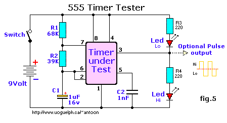 taken from this awesome 555 website, which you should read thoroughly. Make sure everything is right. Then probe the capacitor voltage. It should be changing between 1/3Vcc and 2/3Vcc. If it's above 2/3, make sure your discharge pin is attached. If it's below 1/3, make sure the trigger pin is attached. If it falls and rises between 1/3 and 2/3, then it's working. turbo sex bat 4000 posted:What's the best sketchy ebay store/angelfire website to buy luxeon type high power LEDs from?
|
|
#
?
Feb 14, 2008 17:27
|
|
|
Nevermind, I figured it out.
Wonder_Bread fucked around with this message at 00:06 on Feb 15, 2008 |
|
#
?
Feb 14, 2008 22:48
|
|
|
mtwieg posted:Umm you should never touch an output directly to a low impedance (either supply rail). That'll kill the IC quick. Touching thresh to Vcc should make the light should go off, so that's okay. quote:Make sure everything is right. Then probe the capacitor voltage. It should be changing between 1/3Vcc and 2/3Vcc. If it's above 2/3, make sure your discharge pin is attached. If it's below 1/3, make sure the trigger pin is attached. If it falls and rises between 1/3 and 2/3, then it's working. When the light is on, the cap is at rail voltage. When the light is off, it's at 0v. I think these chips are burned out.
|
|
#
?
Feb 15, 2008 11:12
|
|
|
turbo sex bat 4000 posted:What's the best sketchy ebay store/angelfire website to buy luxeon type high power LEDs from? https://www.dealextreme.com
|
|
#
?
Feb 15, 2008 15:18
|
|
|
sithael posted:My pack of linear ics had 11 apple II sound chips. I wish i knew how to use them. I also got 26 hex inverters which make easy oscillators. poo poo I'll take them off your hands. I can figure out how to work them.
|
|
#
?
Feb 15, 2008 21:23
|
|

|
edit: Nevermind, I found the info I was looking for. I just didn't look hard enough.
iamlark fucked around with this message at 08:23 on Feb 19, 2008 |
|
#
?
Feb 19, 2008 07:22
|
|
|
could you post the whole thing? I can't make heads or tails of the table.
|
|
#
?
Feb 19, 2008 07:28
|
|
|
...
iamlark fucked around with this message at 08:22 on Feb 19, 2008 |
|
#
?
Feb 19, 2008 08:00
|
|
|
iamlark posted:... cool
|
|
#
?
Feb 19, 2008 11:41
|
|

|
A Tutorial for Starting with ATMEL AVR Microcontrollers This is pretty good.
|
|
#
?
Feb 21, 2008 13:46
|
|

|
I got my Jameco grab bags the other day and drat were the parts crappy. I recommend the Electrolytic grab bag without question but the TTL one was basically 40 line buffers and a few CMOS NAND gates. Nothing really worth it at all. The Analog IC bag was just a ton of poo poo that is basically useless. I guess you get what you pay for.
|
|
#
?
Feb 26, 2008 03:06
|
|
|
Cuw posted:I got my Jameco grab bags the other day and drat were the parts crappy. I recommend the Electrolytic grab bag without question but the TTL one was basically 40 line buffers and a few CMOS NAND gates. Nothing really worth it at all. The Analog IC bag was just a ton of poo poo that is basically useless. I'm not so sure I can recommend the grab bag for resistors. I didn't get a single resistor between 43 ohms and 2.2K ohms, and the vast majority (over 1/3rd) were 3.3K Ohm resistors. I didn't order the grab bag to get a bag full of the same resistor!
|
|
#
?
Feb 26, 2008 03:45
|
|
|
Finally got my Futurlec stuff. The Linear IC grab bags had alot of common ics (alot of voltage regulators though) , but all the grab bags are organized and labeled into smaller baggies. Cool, I hate sorting stuff!
|
|
#
?
Feb 28, 2008 21:20
|
|
|
sithael posted:Finally got my Futurlec stuff. The Linear IC grab bags had alot of common ics (alot of voltage regulators though) , but all the grab bags are organized and labeled into smaller baggies. Cool, I hate sorting stuff! That's amazingly awesome. Jameco just kind of lumps everything together and sends it out the door. Sorting parts suck, especially when you can barely read the drat letters on some of those ICs. And yeah, Jameco's resistor pack was kind of worthless. Lots and lots of 10k ohms, but nothing over 100kohms at all. That's kind of important for some things, you know? Their electrolytic grab bag was alright though, I actually use those.
|
|
#
?
Feb 29, 2008 05:50
|
|
|
clredwolf posted:That's amazingly awesome. Jameco just kind of lumps everything together and sends it out the door. Sorting parts suck, especially when you can barely read the drat letters on some of those ICs. I definitely recommend the elecrolytics because they are a good range of values and voltage ratings and are actually useful. Oh i got the potentiometer grab bag and it was good too. Huge range of values and its a pain in the rear end to find proper potentiometer values. For resistors you can get a presorted box of 1-1MOhm values from most electronic stores.
|
|
#
?
Mar 1, 2008 07:36
|
|
|
I know, I was just kind of hoping the jameco grab bag would be sufficient. I've got some megaohm resistors lying around anyways, so I'm alright there.
|
|
#
?
Mar 1, 2008 19:42
|
|
|
Easy question: If I have 12V DC power supply, with 3 30mW LEDs (3.5V typical forward Voltage typical) in series, what resistor do I need (type, resistance and W)?
|
|
#
?
Mar 1, 2008 20:16
|
|
|
Jabab posted:Easy question: No freebies - 3 LEDs, 3.5V each... that's 10.5 volts, yes? 12 - 10.5 = 1.5V Your resistor must drop 1.5V. I'm assuming you meant 30mA not 30mW. That's 0.03A. So: R = V/I. V = 1.5V, I=0.03A. Do the math, pick the closest standard nominal value to the calculated R. scholzie fucked around with this message at 07:37 on Mar 2, 2008 |
|
#
?
Mar 2, 2008 07:27
|
|

|
Edit: I won't ruin the fun
|
|
#
?
Mar 2, 2008 07:28
|
|

|
wuddup posted:Edit: I won't ruin the fun You referring to my [/ma] or something else? I've been up for close to 30 hours now because I was moving and I'm probably nothing (edit: "not" - see?) thinking straight enough to be posting on the internet. I'm too wired from caffeine to go to sleep though.
|
|
#
?
Mar 2, 2008 07:38
|
|
|
Nah, I had solved it and didn't want to spoil the answer.
|
|
#
?
Mar 2, 2008 07:41
|
|
|
oh, ok. I am apparently paranoid, too ")
|
|
#
?
Mar 2, 2008 07:42
|
|
|
scholzie posted:No freebies - 3 LEDs, 3.5V each... that's 10.5 volts, yes? 12 - 10.5 = 1.5V I would've thought it would be I=0.03A*3 so 1.5/0.09 because there's 3 LEDs. Also there's different types of resistor like 5% 0.25W resistors for example. How do you know what to pick?
|
|
#
?
Mar 2, 2008 14:46
|
|
|
Jabab posted:I would've thought it would be I=0.03A*3 so 1.5/0.09 because there's 3 LEDs. Jabab posted:Also there's different types of resistor like 5% 0.25W resistors for example. How do you know what to pick? P=I*V In your case it should be 1.5v * 30 mA = 0.045 W A 1/4 watt should be fine
|
|
#
?
Mar 2, 2008 16:43
|
|
|
Jabab posted:I would've thought it would be I=0.03A*3 so 1.5/0.09 because there's 3 LEDs. Also there's different types of resistor like 5% 0.25W resistors for example. How do you know what to pick? Nope, connected in series, the same current flows through all components. If 30mA is going through one, it goes through them all. Once you find your resistor's value, you can calculate the power with P=I^2*R. From the above, that's 50ohms, so .03^2*50=.045W, or 45mW; a 1/4W resistor is plenty. Even if they are 30mW LEDs, you can still get a current from them directly I=P/V. .03/1.5=20mA. Using 20mA, that's a 75ohm resistor, coincidentally at 30mW. 1/4W is still fine. babyeatingpsychopath fucked around with this message at 20:59 on Mar 2, 2008 |
|
#
?
Mar 2, 2008 16:49
|
|
|

|
| # ? May 21, 2024 17:34 |
|
|
babyeatingpsychopath posted:Nope, connected in series, the same current flows through all components. If 30mA is going through one, it goes through them all. Once you find your resistor's value, you can calculate the power with P=I^2*R. .03 W / 1.5 V = 20mA, not 200mA. You can't divide a number by a number > 1 (edit: oops) and get a bigger number than you started with. You'd need a 75Ω resistor. scholzie fucked around with this message at 23:13 on Mar 2, 2008 |
|
#
?
Mar 2, 2008 17:37
|
|