


|
Could anyone help expain this tuned plate tuned grid triode oscillator?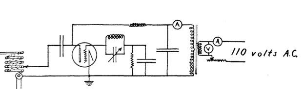 I understand the the tuned grid circuit, although I am not sure how to figure out the capacitance for the grid leak part. I am confused by the tuned plate part of the circuit though, as normally you just see a simple LC parallel circuit but here it's not quite that simple.
|
 #
?
May 15, 2008 16:04
#
?
May 15, 2008 16:04
|
|


|

|
| # ? May 21, 2024 17:52 |
|
|
Efficiency: Dealing with reality Efficiency is simply how much of the power consumed by the supply is delivered to the load. Typically, monolithic switchers have better than 80% efficiency, and with good design and certain applications, it's possible to get over 90%. For something as simple as our circuit, we shouldn't expect more than 75%. Remember, the power dissipated across a component is equal to the voltage across it multiplied by the current through it, or P = VI. As is turns out, the flyback diode (sometimes called the catch diode) is the main factor in efficiency. There are several characteristics of this diode that affect efficiency, but first we'll cover two characteristics that are more important because they determine whether your circuit will work at all: Reverse breakdown voltage: This is the maximum reverse voltage that the diode can withstand before is starts conducting current in the reverse direction. Our diode is meant to act as a one way path for current, so we have to make sure this voltage is never exceeded. For our boost converter, the diode will have a reverse voltage equal to the output voltage during the "on" state. Therefore the reverse breakdown voltage of our diode must be greater than our desired output voltages. Maximum continuous/average current: Obviously all components have limits to the amount of current they can handle. This is where germanium diodes suck; they can generally take maybe 10ma tops, so they're infeasible for power supplies. When selecting a diode, just make sure the max current ratings are considerably greater than what you intend to draw from the supply. So those two parameters must always be satisfied no matter what. Now lets look at characteristics that determine efficiency. Forward voltage (Vf): This is simply the voltage around which the diode starts to conduct in the forward direction. The higher the Vf, the more power it dissipates, so we want a diode with a low Vf for high efficiency. Simple as that. Reverse recovery time (Trr): This is a tricky one to understand. I'm going to copy something out of a writeup from one of my professors for this: quote:All diodes exhibit a "reverse recovery time", Trr, when the circuit changes from the foreword-biased (conducting) condition to the blocking, or reverse-biased condition. During this transition the forward-biased diode looks somewhat like a capacitor; when the voltage across it is rapidly switched from forward conduction to the reversed polarity, a large current will briefly flow through the diode in the reverse (cathode to anode) direction. If a diode is conducting in the forward direction and we wait for a period that exceeds the Trr before attempting to apply a reverse voltage, there will be no such current spike. So what kind of diode do we want? It really comes down to two main types of diodes: "normal" silicon diodes and schottky diodes. For most applications, schottky diodes are the best. They have lower Vf than silicon diodes (less than 0.4V as opposed to more than 0.6V with silicon) and they have much shorter Trr. The only limitation of schottkys is that their reverse breakdown voltage is generally lower (usually around 40V, but sometimes up to 100V). So in general, unless you're dealing with very high voltages, schottkys are the way to go. After the diode, the next most major power waster is the switch in the boost circuit. The switch will dissipate power in two ways: static and dynamic losses. Static losses are those that happen while the circuit is in its on and off stages. In a perfect switch (which looks like a perfect short or a complete break), this will be zero, because the switch will never be conducting with a voltage across is. During the off state there is no current but large voltage drop, and during the on state there is large current but no voltage drop, and in both cases the switch dissipates no power (remember p = vi). Real switches aren't perfect, but you can get pretty close. MOSFETs are great for static power dissipation because their gates draw no current, they have very low leakage current, and they can conduct very well. Usually the on state of a MOSFET is characterized by an equivalent resistance between its drain and source which can be very small (less than 0.1 ohms). We'll just limit our talk to mosfets now, since they're really just awesome. Dynamic losses occur during the transitions between the on and off states. For example, as the switch turns from off to on, it will go from zero current and some voltage to some current and zero voltage, but some time in between it will be drawing some current and will see some voltage, and will therefore draw significant power. Because of this we want our transitions to be as fast as possible, especially if we want to operate at high frequencies. The transition time of MOSFETS is primarily determined by two parameters called the gate source capacitance (also called input capacitance) and the gate drain capacitance (also called reverse transfer capacitance). Without getting too technical, I'll just say that you want to keep these parameters low for fast transitions (under 1000pF). However, unless you're trying to operate in the hundreds of KHz range, this shouldn't be a big deal. If you do want to go very fast, then there are tricks that can be used to improve transition times, but I won't go over them here. The last significant source of power loss is the circuitry in the supply itself. This is really just determined by design, and is usually negligible compared to other losses. The oscillator will be the main consumer, so higher frequency circuits will draw more. For our version, you could probably get it to draw a few milliamps at 40KHz. So if it isn't apparent already, when designing switching supplies you will generally have to sacrifice performance in certain areas for improvements in others. If efficiency is paramount, then you'll want lower frequency of operation to reduce dynamic losses in the diode and MOSFET. If you want low output ripple and fast response, then you'll want very high frequency. It's just a matter of striking a balance between performance parameters. At this point I've covered most of the important stuff. Anything more would likely be nitpicking and miscellaneous crap, unless I chose to get way more technical. If I think of anything else important to add, I'll do so. But if anyone has any questions or comments, now is the time to voice them. ANIME AKBAR fucked around with this message at 06:16 on May 16, 2008 |
|
#
?
May 16, 2008 06:11
|
|


|
I've been following this thread for a few months and want to get started with some hobby electronics now that the semester is over. I'm wondering what sort of setup I'd need to get going. I'm interested in playing around with an Arduino microcontroller as an end goal, but I'd like to have enough components and hardware to learn some basic circuit theory and do some simple projects using a text like Horowitz and Hill. I've noted the links to getting grab bags of resistors, capacitors, and other components, and finding a breadboard is no big deal, but I don't know where to start as far as power supplies go. I don't have the cash to get a benchtop power supply, so what am I looking at--batteries, wall warts? I'd also like to be able to play with some AC circuits in addition to DC. I'm okay with limited frequencies if there's a cheap way to make it happen. I picked up an old Tek oscilloscope, so I'd really like to get some stuff AC stuff to look at after I get some of the basics down. What are my options for DC and AC?
|
|
#
?
May 18, 2008 00:12
|
|
|
DC is far, far easier to work with. At my school, we were encouraged to: A) Book a lab that had variable DC power supplies B) Use 9 volt batteries, possibly alongside a 5 volt regulator if we were working with digital stuff, or C) Use the power supplies that we designed and manufactured as a term project. Option A probably isn't available to you, and option C took a couple months to build and $80 in parts. Option B just sucks. What a classmate of mine started doing out of frustration at our limited options, was just using a cellphone charger. Buy a 5v cellphone charger at a mall or something, shouldn't cost more than $10. Then, just split the output wire. Put them in banana jack output plugs or something from radio shack.
|
|
#
?
May 18, 2008 00:51
|
|

|
For a good prototyping kit, I recommend the Graymark triple power supply breadboard. It's just a breadboard with built in DC supplies. Two a 0-15V positive adjustable rail, a 0-15V negative adjustable rail, and a fixed 5V positive rail, all with 300ma current limits. It comes as a kit you build yourself. It includes all components, so all you need is a soldering iron and a couple other basic tools. The instruction guide is written like a text book so you learn a good deal about how it works as you build it. For less than a $100, I'd say it's a good investment for someone who needs a solid setup and wants to learn some things along the way.
|
|
#
?
May 18, 2008 05:44
|
|
|
SnoPuppy posted:If you ground the negative rail, everything in the opamp will be referenced to a "virtual ground" that is Vcc/2. Thus, you would need to AC couple the input and outputs, otherwise you will get a signal that has a strong DC offset. not all opamps will function without a negative supply. A lot will just do nothing unless you power them properly so be careful with this and read the datasheet.
|
|
#
?
May 18, 2008 17:15
|
|


|
What is a good way to get started with microcontrollers? I am taking an Embedded Systems class right now and we're using Xilinx MicroBlaze, which is a soft-core VHDL microprocessor that you synthesize onto an FPGA. Its pretty cool because you can synthesize all kinds of on-chip peripherals (UARTS, timers, memory, etc) depending on what you want for your design, but the board itself is kind of expensive, so I'm looking at a number of cheaper hardware uCs to use in smaller projects. I know the AVR is popular, but I'm looking at all the info at https://www.avrfreaks.net and its kind of intimidating - whats a good AVR chip and development/programming platform to start with? I'm not necessarily tied to the AVR, either, it just seems like its a popular platform.
|
|
#
?
May 18, 2008 22:37
|
|
|
ante posted:What a classmate of mine started doing out of frustration at our limited options, was just using a cellphone charger. Just a quick word of warning, if the charger is 1) switchmode, and 2) has a two pin (ungrounded) plug, the output may float at half your mains voltage (wrt ground) due to one or more class Y1 capacitors which may be connected between the primary (mains) and secondary (5V) circuits to lessen EMI. see the schematic here on page 6 (CY1 is the capacitor in question). This can be more than enough to destroy sensitive parts... and damage some not so sensitive parts if you plug in connections to other grounded equipment while things are powered up. SMPSs with a 3 pin plug (i.e. they're grounded) or linear supplies don't have this problem.
|
|
#
?
May 18, 2008 23:01
|
|
|
PickledFetus posted:What is a good way to get started with microcontrollers? I am taking an Embedded Systems class right now and we're using Xilinx MicroBlaze, which is a soft-core VHDL microprocessor that you synthesize onto an FPGA. Its pretty cool because you can synthesize all kinds of on-chip peripherals (UARTS, timers, memory, etc) depending on what you want for your design, but the board itself is kind of expensive, so I'm looking at a number of cheaper hardware uCs to use in smaller projects. I know the AVR is popular, but I'm looking at all the info at https://www.avrfreaks.net and its kind of intimidating - whats a good AVR chip and development/programming platform to start with? I'm not necessarily tied to the AVR, either, it just seems like its a popular platform. an atmega16 is a really nice full featured micro and I would recommend it from my experience.
|
|
#
?
May 19, 2008 05:14
|
|
|
Cuw posted:an atmega16 is a really nice full featured micro and I would recommend it from my experience. I'm also curious about a good development platform to start with. It seems like there is a million different compilers, programmers, integrated boards, development kits and such for the AVR family of uCs, so I'm trying to figure out a good way to start out.
|
|
#
?
May 19, 2008 05:40
|
|
|
PickledFetus posted:I'm also curious about a good development platform to start with. It seems like there is a million different compilers, programmers, integrated boards, development kits and such for the AVR family of uCs, so I'm trying to figure out a good way to start out. I use the STK500 programming hardware (80$) with atmel AVRstudio (free). Both are from atmel and have tons of support both from atmel and the public communities. I taught myself how to use AVRs and these have worked fine with me. Don't be too intimidated by avrfreaks. It's a great community, but it's very technical since a lot of guys there are professional level developers, but they're pretty newbie friendly.
|
|
#
?
May 19, 2008 05:47
|
|
|
I would recommend an AVR Butterfly. It's about $20, it has an ATMega 169P, an LCD, a little joystick, and a buzzer. You can connect it directly to a PC's serial port for programming it using AVR Studio, so you don't need to buy a programmer. Later on you might feel a bit limited by a Butterfly, but it's great for playing around at first.
|
|
#
?
May 23, 2008 17:44
|
|


|
I would like to make a simple 3d mouse for my computer, it is not going to be used for anything needing accuracy, just as a little toy. I can handle the programming, it is the hardware I need help with. I would make it with a couple boom arms, with sensors at the joints. The sensors would not have to be sensitive, within a few degrees. What I am asking is what the CHEAPEST method to go about this is. If I have to pay a little more to make all of the parts reusable, fine. I have almost no electronics experience, though I am willing to learn. What I was thinking was I would make the boom arm, and attach some trimpots to the joints to act as sensors (How accurate would they be?). I would find some sort of usb logic board, and wire it to the trimpots. One requirement is that I am able to access the usb (Or serial, or whatever) board with C++, so it would need some libraries for that. I don't need to program it in C++, just read from it. Is this even vaguely a good idea? Can I do the electronics for it for under $100? What I am hoping to do with this is expand it to a hand sensor, so I could sense finger positions and so on.
|
|
#
?
May 27, 2008 20:06
|
|

|
Battle Bott posted:Is this even vaguely a good idea? Can I do the electronics for it for under $100? I think trimpots at the axes of the joints will work for your first draft, but for a full hand you'd probably want some linear potentiometers above the joint so you can get your fingers closer together. A handful of trimpots/linear potentiometers and a multichannel ADC that speaks USB should run you way less than $100.
|
|
#
?
May 27, 2008 20:15
|
|


|
Hey guys, I'd like to design an automatic drip-irrigation system for my garden. Unfortunately, I can't find any cheap source for small flow-meters or valves. Do such things exist? The sort of pressures and flows I'll be dealing with are seriously negligible, and accuracy isn't a big deal. Anyone have any ideas?
|
|
#
?
May 27, 2008 20:17
|
|
|
babyeatingpsychopath posted:I think trimpots at the axes of the joints will work for your first draft, but for a full hand you'd probably want some linear potentiometers above the joint so you can get your fingers closer together. Ah, I had forgotten all about linear potentiometers. Does anyone know of a good model for the ADC that fits my needs? C++ libraries, a bunch of channels, (Enough for an entire arm?) and usb. Battle Bott fucked around with this message at 22:47 on May 27, 2008 |
|
#
?
May 27, 2008 22:39
|
|
|
Battle Bott posted:I would like to make a simple 3d mouse for my computer, it is not going to be used for anything needing accuracy, just as a little toy. I can handle the programming, it is the hardware I need help with. I would make it with a couple boom arms, with sensors at the joints. The sensors would not have to be sensitive, within a few degrees. Use some wiimotes to do this. You can find a 3d position by using 2 wiimotes. Have an IR led on a glove to find that points position. You could probably find a particular orientation by using 3 LEDs, but if you go with more LEDs you will probably have to figure out how to multiplex them. The easiest way would be to turn certain LEDs off for some fames. Tons of ways you could do this. I would use IR and multiple cameras.
|
|
#
?
May 27, 2008 23:30
|
|
|
ValhallaSmith posted:Use some wiimotes to do this. You can find a 3d position by using 2 wiimotes. Have an IR led on a glove to find that points position. You could probably find a particular orientation by using 3 LEDs, but if you go with more LEDs you will probably have to figure out how to multiplex them. The easiest way would be to turn certain LEDs off for some fames. I've actually done this. I remade that virtual room thing in Garry's Mod. I'd like to try the trimpot thing though. Hmm. I am having trouble finding any cheap large number of channel usb ATD boards. A freind linked me to the Arduino, but it is only 6 channel. Is there an easy way to make a splitter of some sort? Battle Bott fucked around with this message at 01:23 on May 28, 2008 |
|
#
?
May 28, 2008 00:21
|
|
|
Battle Bott posted:I've actually done this. I remade that virtual room thing in Garry's Mod. I'd like to try the trimpot thing though. You need an analog multiplexer. Quick digikey search: http://search.digikey.com/scripts/DkSearch/dksus.dll?Detail?name=MC74HC4066ANGOS-ND Hook all of the outputs together to one ADC pin and use some regular digital pins to control which signal you are reading. turbo sex bat 4000 fucked around with this message at 03:26 on May 28, 2008 |
|
#
?
May 28, 2008 03:18
|
|

|
http://www.mypic32.com/web/guest/home Just thought I'd share this with everyone. It's a design contest that looks like it will be pretty easy to get free goodies from (you just need to make it past the first round, and 128 people will get debug kits). I was going to enter, but then I read the details that the companies involved are granted limitless licenses to anything you create, and they are allowed to sublicense, etc. Basically, you come up with ideas, they pick the good ones, give you a few small prizes, and sell them to companies for a lot more. Wouldn't be hard to come up with a BS project with some good drawings and details to get past the first round, though.
|
|
#
?
May 28, 2008 04:47
|
|


|
Mr. Powers posted:http://www.mypic32.com/web/guest/home I just took a look at this and it looks like a decent contest. I question having so many entertainment prizes when it might make more sense to have sponsors offer test equipment. Tektronix giving away a 10K$ oscilloscope would be better than a home entertainment system. I'll probably go with an all in one low powered synthetic instrumentation setup. I see that a few people have similar projects, but they really don't take a general approach. I figure if I can get a few channels of DDS function generator outputs, some ADC inputs and some sort of internal mux it might work out. It would need to have useful functional equivalents for function/Arbitrary waveform generation, oscilloscope, volt, ohm, frequency counting, spectrum analyzer, something else I am probably missing. Tie this together with a GUI based instrument building program. Have it connect to PCs via ethernet. Support LXI triggers and IEEE timing.
|
|
#
?
May 28, 2008 08:04
|
|
|
Mr. Powers posted:http://www.mypic32.com/web/guest/home gonna have to throw something together in visio so it looks really pretty.
|
|
#
?
May 28, 2008 15:43
|
|
|
I'm thinking about building a metronome, and shopping for some components. Has anybody had any experience with little LCD character modules? (http://www.lumex.com/product.aspx?id=463) The datasheets are wonderfully vague. I was hoping to drive the characers with digital i/o ports like a 7 segment display (but using less power, hence LCD) but it claims it wants 5V AC. Does this have to be true AC? would rapidly switching DC be alright? does this mean 0-5V or -5-5V? So many unanswered questions, and I really don't feel like ordering one to blow up experimenting with/decide it won't meet my requirements.
|
|
#
?
May 28, 2008 23:59
|
|

|
Delta-Wye posted:I'm thinking about building a metronome, and shopping for some components. Has anybody had any experience with little LCD character modules? (http://www.lumex.com/product.aspx?id=463) The datasheets are wonderfully vague. I was hoping to drive the characers with digital i/o ports like a 7 segment display (but using less power, hence LCD) but it claims it wants 5V AC. Does this have to be true AC? would rapidly switching DC be alright? does this mean 0-5V or -5-5V? So many unanswered questions, and I really don't feel like ordering one to blow up experimenting with/decide it won't meet my requirements. IIRC you have to switch the 0/5V back and forth at a few hundred Hz so that it doesn't die. It doesn't need a sine wave, just alternating polarity.
|
|
#
?
May 29, 2008 05:13
|
|
|
turbo sex bat 4000 posted:IIRC you have to switch the 0/5V back and forth at a few hundred Hz so that it doesn't die. It doesn't need a sine wave, just alternating polarity. That would be fairly trivial. When you say alternating polarity, does that mean the common leg should be 2.5V? If not, does this vary from PWM at all (which is what it sounds like)? Thanks!
|
|
#
?
May 29, 2008 05:21
|
|
|
It is different from PWM. You want to switch the common between 0 and 5V rapidly. To turn on a segment, you switch the desired pin out of phase with the common.code:
|
|
#
?
May 29, 2008 05:45
|
|
|
turbo sex bat 4000 posted:It is different from PWM. You want to switch the common between 0 and 5V rapidly. To turn on a segment, you switch the desired pin out of phase with the common. You should write datasheets or something buddy. That made a hell of a lot more sense than most anything I've been able to find on google. If you don't mind one more question, any ballpark idea on current draw? I assume by being out of phase with the common, you get a little current flow either way. Does it average close to zero or so? I ask as I'm trying to decide if I want to drive the digits directly, or through logic.
|
|
#
?
May 29, 2008 05:52
|
|
|
Off hand, does anyone know of a cheap (<$30) and efficient 12V ~120W AC-DC power supply?
|
|
#
?
May 30, 2008 01:17
|
|
|
dyne posted:Off hand, does anyone know of a cheap (<$30) and efficient 12V ~120W AC-DC power supply? Find a used computer parts store and see if you can find a laptop power brick close enough?
|
|
#
?
May 30, 2008 02:56
|
|
|
Delta-Wye posted:You should write datasheets or something buddy. That made a hell of a lot more sense than most anything I've been able to find on google. If you don't mind one more question, any ballpark idea on current draw? I assume by being out of phase with the common, you get a little current flow either way. Does it average close to zero or so? I ask as I'm trying to decide if I want to drive the digits directly, or through logic. My guess is that it draws probably next to nothing. The things are used in calculators etc after all.
|
|
#
?
May 30, 2008 04:49
|
|
|
Delta-Wye posted:I'm thinking about building a metronome, and shopping for some components. Has anybody had any experience with little LCD character modules? (http://www.lumex.com/product.aspx?id=463) The datasheets are wonderfully vague. I was hoping to drive the characers with digital i/o ports like a 7 segment display (but using less power, hence LCD) but it claims it wants 5V AC. Does this have to be true AC? would rapidly switching DC be alright? does this mean 0-5V or -5-5V? So many unanswered questions, and I really don't feel like ordering one to blow up experimenting with/decide it won't meet my requirements. It needs -5 to 5 for it not to die in a couple weeks. The way that I did it in class was to use an XOR gate for each of the LCD's pins. Something like this:  You'll need a gate for each of the 8 LCD inputs (A-G, and DP if you want it), so two XOR chips.
|
|
#
?
May 30, 2008 11:24
|
|
|
So I've got a question, and I figured if there was anywhere to turn for reliable knowledge it was SA. I'm designing a pair of circuits that act as remote I/O controllers for a series of home-made servers. I've got one board whose power supply will be the 5v line from a computer power supply. The schematic and protoboard are finished and functioning, and now I'm on to the PCB design. I'm brand new at this and not really sure what to do a lot of the time. I'm designing the board using Eagle 5.0.0 Light. I think I've got most of it worked out, but there are a few things I could use a little assistance with: 1) Ideally I'd like to place a reciever for a standard 4-pin Molex connector (like this guy) built into the PCB board. I have no idea where such a part would exist in the standard Eagle Libraries. Any ideas? The socket labeled X2 is the Molex 4-pin duel line, and I need it all in one line. That one's just filler on the schematic. 2) If I can't find such a connector in the standard libraries I could then resort to putting 4 solder-pads on the PCB board and just solder the wires straight in. I've never done this so I'm unsure how large should the solder-pads be? Are they just holes in the PCB board with a little metal ring around them or did I find an image of somethign else. 3) What's a via? Is it just a spot where the built-in lines on the board (what are those called?) cross from one side to the other? 4) I used Eagle's "auto" function to lay out those built-in lines for all of the devices. Is it something I can trust? I'll include an image of what it gave me below - if anybody with experience sees any blaring problems please point them out to me as I want to get this right - it's for work and I'm an intern looking for a good letter of recomendation. Any help will be extremely appreciated. 
|
|
#
?
May 30, 2008 14:12
|
|

|
Cannister posted:So I've got a question, and I figured if there was anywhere to turn for reliable knowledge it was SA. 1) Not sure - its possible that they don't have one. Do they have a connector section? Try looking there - you may have to find a similar part to put down. 2) Look at the data sheet for the connector - it will tell you the exact mechanical dimensions for the part, including pin pitch/solder pad size. Normally "solder pad" refers to a surface mount connection and a plated through hole is for through hole pins or wires. If you decide to solder wires, just drop down 4 header pins - those should be through hole. 3) Yes 4) I never like to trust the auto router in any tools. You can almost always do better by hand routing it, but its your call. I would have to examine the routes a bit more to offer anything definitive in your case.
|
|
#
?
May 30, 2008 14:50
|
|
|
I had an idea for a simple electronic organ but my main stumbling block seems to be finding suitable buttons. The design is going to be 12 oscillators (one for each note) with the output connected directly to a switch and then all the outputs will be mixed together and fed into an amp or speaker or something. My problem is that a lot of the buttons I've found are either too small, too expensive or too "heavy duty" for the job.
|
|
#
?
Jun 2, 2008 23:43
|
|

|
mofmog posted:I had an idea for a simple electronic organ but my main stumbling block seems to be finding suitable buttons. The design is going to be 12 oscillators (one for each note) with the output connected directly to a switch and then all the outputs will be mixed together and fed into an amp or speaker or something. My problem is that a lot of the buttons I've found are either too small, too expensive or too "heavy duty" for the job. An old radio shack kit organ I had before was just a simple piece of metal over a screw. Push on the end of the piece of metal and it bend down to contact the screw. Works pretty well as long as you aren't too rough with it.
|
|
#
?
Jun 3, 2008 07:53
|
|
|
BTW, signing up for the PIC32 design challenge gets you into the community giveaways whether you have an entry or not. I haven't posted my design yet, but I got an email today saying I won a book on programming the PIC32. Next week, they are giving away three I2C/SPI bus adapters (I assume some sort of USB dongle for PC).
|
|
#
?
Jun 4, 2008 23:33
|
|
|
Troubleshootin' time! I'm attempting to build a direct-in box for my bass and 6-string guitar to use as an input preamp/isolator to the line in of my Macbook. Concept: Unity gain follower on the input, driving a voltage divider level control, driving a 101:1 voltage amp, into a current amp biased for about 60 mA collector current. The LM324 was in my junkbox in quantity and seems to be able to source plenty of bias current. Here is the circuit that I have cranked out. It looks okay when simulating, giving up to a 101:1 voltage gain and driving a 100 ohm load like gangbusters. I built it up last night adhering to the schematic and in the real world, I get terrible,terrible distortion at all levels. I'm suspecting that I've got something retarded going on with the various input/load resistors. I am not too good with level controls, or op amp load/input resistors. I tried to get by but it certainly sounds like I boned something up. Here is the schematic. Does anybody see glaring problems that might cause this? Am I running too much collector current? Output resistor is 4x 470 ohm in parallel for a 115 ohm 1w resistor. 
|
|
#
?
Jun 11, 2008 20:00
|
|


|
Jonny 290 posted:Troubleshootin' time! and you'll never get the necessary performance out of a POS like an LM324. Its gain bandwidth product and slew rate are terrible. Its input bias currents are also too large for feedback resistors higher than around 10K. You'll want an amp for your gain of 101 amplifier with a GBP of at least 4MHz. Something like a TLC084/TLC082 would be much better. third, you'll likely want something better than a class A amplifier (is an emitter follower a class A?...) output stage. A class A/B will work much better, but will require some fine tuning to get the crossover distortion to a minimum.
|
|
#
?
Jun 11, 2008 21:22
|
|
|
Yeah, I'm teaching myself AB amps on the side and they are screwing my head pretty good. That's the next stage, after I can figure out how to properly pick an opamp and get this one humming. I have a TL061ACN and a TL082CP in the parts box. I figure either of those would be a better match. Thinking about the power supply issue, I may just bite the bullet and build a dual rail linear supply off this transformer, rather than trying to BS with split rails and wall warts. Figure I could do that for under $20, and I need practice with linear supplies anyways. Further edit: Let's nail this bastard down so it works solid and I can contribute the interface schematic to home recording nerds down in ML! I see "how do i plug my guitar into my sound blaster" questions almost daily still. Jonny 290 fucked around with this message at 23:00 on Jun 11, 2008 |
|
#
?
Jun 11, 2008 21:32
|
|
|

|
| # ? May 21, 2024 17:52 |
|
|
a TL082 might be good enough. A gain of 101 is pushing it a bit, but I doubt it'll make a noticeable difference. And its jfet inputs mean you can use larger feedback resistance. Just make sure your supply voltage is enough, like at least +/- 10V (+/- 15V is normal).
|
|
#
?
Jun 12, 2008 04:35
|
|