


|
why not do two gain stages in series each with a gain of somewhere around 10? The LM324 is a quad opamp IC after all, and this will give you an overall gain of 100 leaving one opamp free for an output buffer. Other thoughts: is a gain of 100 close to your supply rails? Even though the LM324 can work on a single supply, you'll still need to bias your input signal. something like: 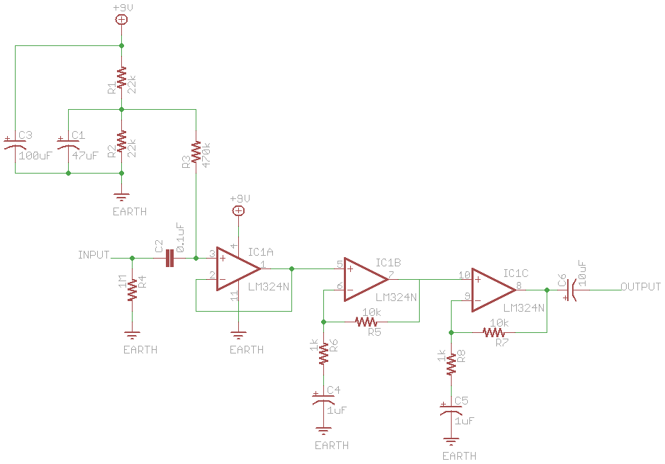 This should give a voltage gain of 121 (11x11). R1 and R2 set your bias voltage, in this case 4.5V or half of the supply (9V, but 12V should be fine) Because resistors (and active components) have thermal noise, and reactances (capacitors/inductors) don't, we add some more components to our biasing network... C1 (47uF, the value like everything else in the schematic, was just chosen arbitrarily) is used to decrease thermal noise from the biasing resistors by shunting it to ground, R3 is a high value resistor (any value higher than 470k is fine) to 1) stop the voltage divider being loaded down by whatever you're biasing, and 2) the lower current through the resistor = the lower the noise. Edit: your volume control should be after the output of the gain sections, otherwise you're just moving your input closer to the noise floor and amplifying that. Edit2: clarification? Noise a result of EMI/RFI is not what I'm talking about. Resistors: have Thermal noise proportional to their absolute temperature (in degrees Kelvin), current noise proportional to the current through them, and some more noise depending on what they're made from (carbon is noisier than metal film). Inductors generate as much noise as a piece of wire does, i.e. next to none, yes it's always there but for practical purposes it can be ignored. If your electrolytic capacitors aren't bubbling, you're doing it wrong. 
Chalupa Joe fucked around with this message at 21:20 on Jun 13, 2008 |
 #
?
Jun 13, 2008 09:39
#
?
Jun 13, 2008 09:39
|
|


|

|
| # ? May 21, 2024 23:06 |
|
|
Chalupa Joe posted:why not do two gain stages in series each with a gain of somewhere around 10? Why do inductors not have noise? I would think being large coils of wire they would act as antennas inducing noise into the circuit. I have also heard of electrolytic capacitors inducing noise because they have all that bubbling goo inside of them. Please set me straight.
|
|
#
?
Jun 13, 2008 15:01
|
|


|
Thermal noise is just that - noise generated by heat. Resistors and active devices dissipate a lot of heat. RF and interference pickup from coils is a non-issue generally unless you are working at high frequencies or in unshielded devices. Inductors have a 'low-pass' behavior. As the frequency goes up, their 'resistance' to the current goes up. Think of them as a resistor that is 0 ohms at DC, but high ohms at AC frequencies. Capacitor is the exact reverse - high resistance (open circuit, in fact) at DC, but low resistance at AC. This is how basic passive filtering works - an LC or RC filter is just a divider network similar to a resistive divider, but using an inductance and capacitance. Here's a high pass filter. code:code:As the frequency goes up, the capacitor will appear as a lower and lower resistance and the inductor a higher and higher one, effectively changing the tap point of the resistance network. Thus, more of this signal passes through to the output. For a low-pass filter, you just exchange the L and C components. The L will be on top, getting larger as the frequency goes up, and the C will be on bottom, becoming less resistive, effectively bringing the level down as the frequency goes up. And there, I just went on a tangent on filters on a work day. I know I mis-termed stuff and know about reactance but figured I'd simplify.
|
|
#
?
Jun 13, 2008 18:43
|
|


|
All of you guys are really reminding me about my Electronic Devices class. It's the class where you learn a lot a transistors and stuff. I just had one problem with it. All of the lessons were so loving biased I'm very sorry for the really bad joke.
|
|
#
?
Jun 15, 2008 05:18
|
|

|
I am truly ashamed for laughing at that.
|
|
#
?
Jun 15, 2008 05:19
|
|


|
I am sad to report that you are not alone. Edit: I mean loving depressed.
|
|
#
?
Jun 15, 2008 06:02
|
|

|
Bush is a QT posted:All of you guys are really reminding me about my Electronic Devices class. It's the class where you learn a lot a transistors and stuff. I just had one problem with it. You're supposed to say that you couldn't resist
|
|
#
?
Jun 15, 2008 07:26
|
|

|
ante posted:You're supposed to say that you couldn't resist or it was really conductive to learning.
|
|
#
?
Jun 15, 2008 07:39
|
|

|
CHECK YOUR GOT-drat PINOUTS I slaved all weekend on a bipolar linear supply and a TL082 preamp because I was sick of rigging up divider networks, and assumed that 78xx and 79xx regulators had the same pinout. WRONG-O. Evidently I blew my 7915 because even after rewiring correctly I'm only getting -3.1v when the unregulated rail is -18, -19 volts or so. My lone 7915. My lone 79xx at all. And the best part is that Rat Shack doesn't carry any 79xx regs and I'm moving in a week, so I don't have the occasion to get one. single. regulator mailed to me. ARGH. On the bright side, I did successfully mask and etch my own power supply PCB and hell, I more or less built a linear supply. First thing I've done that uses 120 directly. I'm stoked, little bit of heatshrink and attention and it's safe as houses. Edit2: Comedy regulator time. I found 15 volt zeners in my box so I'm going to use those to bias a 2n2222a/2n2907 pass transistor pair. 14.5ish volts should work fine for the preamp. I want to see if I can get this poo poo moving, haha. Figuring 4-6v of drop across the transistors with max current of 30 mA absolute tops, quarter watt of power dissipated in each at the most. The power LED's draw more juice than the amp in this circuit, almost. Jonny 290 fucked around with this message at 19:48 on Jun 15, 2008 |
|
#
?
Jun 15, 2008 17:31
|
|
|
Jonny 290 posted:I slaved all weekend on a bipolar linear supply and a TL082 preamp because I was sick of rigging up divider networks, and assumed that 78xx and 79xx regulators had the same pinout. WRONG-O. I too learned this one day, the same way. One of my grad student buddies told me its so you can mount them back to back on a heatsink or something. (EDIT: He's a liar. My whole life is a lie. See below. It doesn't make a lick of sense according to the datasheet) For whatever reason, it pissed me right the gently caress off. Delta-Wye fucked around with this message at 09:15 on Jun 16, 2008 |
|
#
?
Jun 15, 2008 20:37
|
|
|
Delta-Wye posted:One of my grad student buddies told me its so you can mount them back to back on a heatsink or something. Which is exactly what you don't want to do, unless you insulate the metal tab on the regulator - the tab is connected to the negative input on the 79xx series regulator, and ground on the 78xx regulator. This will result in a short on your -ve supply.
|
|
#
?
Jun 16, 2008 07:38
|
|

|
It lives! Instead of linear regs I just pulled out a 2n2222a/2n2907 pair and ran them as emitter followers, using 15v Zeners biased at 10 mA-ish for the base drive. Voltage looks great, 14.32 or so on either rail. Wired it all up and scratched my head until I finally realized that I never connected the inverting input back to the gain network. GAH. Wired it up and the whole thing sprung to life. Great gain, low noise, I'm happy. It's all crammed in a Radio Shack aluminum box so there's a teensy bit of PS hum, but what can you expect for a first power supply, heh. Edit: Further question: On my supply I used a 3 prong cord, used hot/neutral and heatshrinked the ground wire inside the supply, so it's currently disconnected. My PS has a metal case, and the secondary center tap connected to ground. Is it a good idea for me to connect the AC ground to chassis ground? Do I want to maybe put in a ground lift switch to counteract possible ground loop issues (which don't exist in my studio, but may in the field)? Jonny 290 fucked around with this message at 22:25 on Jun 16, 2008 |
|
#
?
Jun 16, 2008 16:17
|
|
|
Battle Bott posted:I've actually done this. I remade that virtual room thing in Garry's Mod. I'd like to try the trimpot thing though. I co-founded fusion controls, and we make a 10 analog in/ 12 digital out USB board... we might be able to work out some academic pricing. https://www.fusioncontrolcentre.com
|
|
#
?
Jun 17, 2008 02:01
|
|
|
I just started and subsequently finished assembling two JAW Wideband boards and one display for them an hour or so ago, and after a pretty long time away from board soldering, good GOD I forgot how much I love it. Populating resistors is just so relaxing. And soldering board mount components? Pure sex.
|
|
#
?
Jun 17, 2008 03:25
|
|
|
Jonny 290 posted:
If you'd like to avoid possible electrocution, it is absolutely imperative that you do this. As for ground loops... in a linear supply, your primary and secondary sides should be electrically isolated? Chalupa Joe fucked around with this message at 10:54 on Jun 17, 2008 |
|
#
?
Jun 17, 2008 10:52
|
|
|
Delta-Wye posted:or it was really conductive to learning. So what's he currently working on? Heck with this piddly "milliamp" crap too - I'm thinking about doing a useful primer on power electronics in this thread. (120V stuff, not the good stuff in the kV/kA range.) Three-Phase fucked around with this message at 11:23 on Jun 17, 2008 |
|
#
?
Jun 17, 2008 11:18
|
|

|
Three-Phase posted:So what's he currently working on? Small signal stuff is neat but I think that working with high current and/or voltage is an interesting and worthy challenge. It's one of the main reasons that I am investigating converting a crotch rocket to electric - I want to build the motor controller myself. Something about PWM'ing 80 amps at 48 volts makes me RRRRRR.
|
|
#
?
Jun 17, 2008 15:17
|
|
|
Ok i'm starting on a project right now to make a scrolling LED display. I am really unsure of what i'm going to need and how to go about it, although I do want to do most of it by myself I figure why not at least get a starting point down. Here is my current plan, I am going to use a ATMEGA16 to control a big ole grid of LEDs. My plan was to make an addressing scheme similar to how RAM is access with a column address and a row address and divide the memory into that, maybe have the column be ground and the row's be hot. When the address is hit the LED will then turn on! Voila easy as pie. The issue with this is I need tons and tons of address lines, unless I multiplex the lines but then speed becomes an issue. How would be the best way of doing this? Am I completely over complicating this because if I am please tell me.
|
|
#
?
Jun 17, 2008 23:32
|
|
|
hey electrical engineers, I have a couple questions about batteries and solar charging. I have a little low power laptop I am considering bringing along with me to our family vacation spot, which is up in the mountains and has no electricity, just propane and gravity and plenty of sun which is why I think about solar panels. it might be a bit of a pain to bring it all along and keep it clean, but it also might be nice to bring a whole library of ebooks and mp3s to enjoy while camping. however solar panels are pretty pricey so I am wondering if it would work out to buy a smallish one, not enough to power the laptop but enough to charge the battery over a day and then run it from the battery for a few hours. If I hook it up to a car charger providing the right amount of volts, but fewer watts than it asks for, would that damage the Li-ion battery somehow, or just charge it slower? all modern laptops should have some electronics in place to prevent over-charging, right? this goes back to my lazy plan of leaving it plugged to the solar panel during the daytime - could that damage the battery? The setup I am imagining right now is: solar panel providing about 10 watts at 12 volts, with a female car power plug, connected by the laptop car charger to the laptop. the laptop's sticker on the bottom says it wants 9.5 volts, 22 watts. so I figure it would charge in about two to three times normal charging time, if it all works right. I would disconnect the panel before turning on the laptop so it wouldn't try to draw power from the wire and find it lacking. so, any tips or caveats or things I might have forgotten? think this would work? google has helped me figure out some of this but it feels like most laptop solar power systems are designed for heavy use or big, power sucking laptops, and they frequently incorporate another big battery that sits between the solar panel and the laptop, consequently they cost way too much... $300... $600... I don't need to run completely from a solar panel, nor do I feel like I need another battery in the mix. If the system I imagine works how it should then this could cost less than $100, or a little over if I go for a neato compact folding panel. thanks for any help.
|
|
#
?
Jun 18, 2008 01:38
|
|

|
Either I'd get a standard solar charge controller, maybe look for one that adjusts down to 9.6v, or I'd reconsider the sealed lead acid battery in the system. It's cheap, 20 bucks for a 7 amp hour and about 40 bucks for a 20 amp hour. $300 is way more than you actually need to pay.
Jonny 290 fucked around with this message at 04:34 on Jun 18, 2008 |
|
#
?
Jun 18, 2008 04:31
|
|
|
Cuw posted:Here is my current plan, I am going to use a ATMEGA16 to control a big ole grid of LEDs. My plan was to make an addressing scheme similar to how RAM is access with a column address and a row address and divide the memory into that, maybe have the column be ground and the row's be hot. When the address is hit the LED will then turn on! Voila easy as pie. The issue with this is I need tons and tons of address lines, unless I multiplex the lines but then speed becomes an issue. How would be the best way of doing this? Am I completely over complicating this because if I am please tell me. Usually, matrix multiplexing is the way to go when controlling an LED array. With an ATMEGA16, speed shouldn't be a problem at all. How big is your LED array?
|
|
#
?
Jun 18, 2008 12:06
|
|

|
Alright here's another question: There are waves of electricity all around us in the air, in particular ones that are meant for cell phones to pickup. From what I remember, cell phones use a darlington pair to amplify the signal by a lot. What is the voltage/current of the cell phone signals in the air around us, and what is your voltage/current by the time they are done being amplified by the phone?
|
|
#
?
Jun 19, 2008 14:13
|
|
|
Those waves do not have a voltage or current, but they will induce a voltage or current as they pass through a conductor. For what it's worth the average level of a signal needed for clear FM reception (what FM radio, police radios, etc) is around 0.16 uV. Field strengths are measured in 'microvolts per meter'. Also, the Darlington doesn't have much to it. At the cellular frequency range you are generaly using FET transistors or more likely MMIC's (monolithic microwave integrated circuits) which are a relatively new tech, bascially an easy to use amplifier block in one chip. Very high frequency and microwave tech is hard to engineer and build, and MMIC's make a lot of commodity situations much simpler.
|
|
#
?
Jun 19, 2008 16:30
|
|
|
Jonny 290 posted:Those waves do not have a voltage or current, but they will induce a voltage or current as they pass through a conductor. I'm a digital guy so I don't really know too much about the black arts of RF design, but I have been wondering what types of gains are required in an RF front end. For example, if I have an average FM antenna, what would the induced voltage from an average FM station be (so I would know how much to amplify to feed an A/D)? I know this is probably too open ended to get much of a response, but I have been curious about some rough numbers (is it on the order of uV? nV?)
|
|
#
?
Jun 19, 2008 17:33
|
|
|
Jonny 290 posted:Those waves do not have a voltage or current, but they will induce a voltage or current as they pass through a conductor. Thanks this answered a question I've had for a while, I love this thread.
|
|
#
?
Jun 19, 2008 20:01
|
|
|
Jonny 290 posted:Small signal stuff is neat but I think that working with high current and/or voltage is an interesting and worthy challenge. It's one of the main reasons that I am investigating converting a crotch rocket to electric - I want to build the motor controller myself. Something about PWM'ing 80 amps at 48 volts makes me RRRRRR. It'd do-able. I'm used to using large SCR "pucks" for switching AC. Except we're talking about maybe 1000 or so amps. You can get different AC signals with lower RMS voltages, as well as creating DC with variable voltage levels depending on how you hook up the SCRs. If you wanted to be really fancy-schmancy, you could hook up some sort of speed transducer, have a feedback loop, and have cruise control.
|
|
#
?
Jun 19, 2008 22:41
|
|
|
RegonaldPointdexter posted:Usually, matrix multiplexing is the way to go when controlling an LED array. With an ATMEGA16, speed shouldn't be a problem at all. I am thinking of doing 10x200 in 5x7 matrices but that seems like a lot of soldering and burned fingers.
|
|
#
?
Jun 20, 2008 20:45
|
|
|
Alright here's another story one of my teachers told in class. The lesson was on transformers. Told from his perspective (he's an engineer) I went to a job interview with a friend of mine who is a very short man, this was a long time ago. He was really short. Now we both went for the interview and the manager asked me the difference between an AC and a DC motor, and I told him and I got the job. My friend went in for the interview, and they made fun of him. They told him to read a poem, he did and they laughed him out of the office. Using his knowledge of transformers he went to the dump and made a transformer out of scrap. He went door to door trying to sell it until he finally sold one. Then he made another and sold it. And so on and so fourth. Now this man owns many factories in india and is richer than me, he could buy me MANYYYYY times, he makes billions! After this I responded out loud (so the whole class could hear me): I guess you could say transformers stepped-up his life!. True story. Ms Jewish Anime fucked around with this message at 03:20 on Jun 23, 2008 |
|
#
?
Jun 23, 2008 02:31
|
|
|
Am I missing something here (I saw the joke and I am choosing to ignore it because of how bad it is)? Why would someone buy a transformer from a door to door salesman?
|
|
#
?
Jun 24, 2008 04:53
|
|


|
Mr. Powers posted:Am I missing something here (I saw the joke and I am choosing to ignore it because of how bad it is)? Why would someone buy a transformer from a door to door salesman? I don't know it was a story my teacher told us.
|
|
#
?
Jun 24, 2008 16:56
|
|
|
Mr. Powers posted:Am I missing something here (I saw the joke and I am choosing to ignore it because of how bad it is)? Why would someone buy a transformer from a door to door salesman? I don't think he was literraly going door to door, but was marketing it to different companies. some-one bought one (got a contract as a supplier) and he made billions.
|
|
#
?
Jun 24, 2008 18:11
|
|

|
s3rca posted:I don't think he was literraly going door to door, but was marketing it to different companies. some-one bought one (got a contract as a supplier) and he made billions. This was probably it. Also I want to ask yet another question, this time about coupling capacitors in amplifiers. I was talking to icon in BYOB about this earlier, and I wanted to confirm it here. For coupling capacitors, is a lower amount of farads always better?
|
|
#
?
Jun 24, 2008 18:23
|
|
|
Welp i found a great guide for making a LED array http://www.acm.uiuc.edu/sigarch/tutorials/ledarray/ looks to be the same thought process I went through too. Welp now to source some LED 8x8 grids and get this project started
|
|
#
?
Jun 24, 2008 21:07
|
|
|
Bush is a QT posted:Using his knowledge of transformers he went to the dump and made a transformer out of scrap. He went door to door trying to sell it until he finally sold one. Then he made another and sold it. And so on and so fourth. The really cool part is that he constructed the transformer in an ISO-9001 certified dump. Mr. Powers posted:Why would someone buy a transformer from a door to door salesman? You know, I've been meaning to get a transformer for my apartment. Except for some NEC issues and the fact that The Illuminating Company outright refused to run a 4160/2400V drop to my apartment. Three-Phase fucked around with this message at 02:56 on Jun 25, 2008 |
|
#
?
Jun 25, 2008 02:53
|
|
|
http://www.sparkfun.com/commerce/product_info.php?products_id=681 found some LED matrixs for anyone that cares. They are 8x8 and the company that sells these even makes a serial backpack so you can just send it a big array and it will decode it and stuff, although they are $50 a pop. It looks to me that I am going to need a ATTiny or ATMEGA on each matrix because there is no way I can address the entire 72x8 array with just a single chip because I need 18 outputs per chip, 2 for each column since they are bicolor LEDs and then 1 for the clocking of the counter.
|
|
#
?
Jun 25, 2008 18:08
|
|
|
Cuw posted:http://www.sparkfun.com/commerce/product_info.php?products_id=681 found some LED matrixs for anyone that cares. They are 8x8 and the company that sells these even makes a serial backpack so you can just send it a big array and it will decode it and stuff, although they are $50 a pop. Hopefully, your clock speed is sufficient to keep the duty cycle up high enough that your LEDs are bright.
|
|
#
?
Jun 25, 2008 18:41
|
|

|
babyeatingpsychopath posted:You could also use some SPI memory interface chips to access the array. You use 2-4 outputs as SPI to the interface chip, then 2 outputs to select the LED color. It looks like an 8k memory interface chip is running about $.35 on digikey. There are also LED specific drivers out there that use SPI. They have the advantage that they can maintain current and allow toggling instead of having to constantly pump an LED>
|
|
#
?
Jun 25, 2008 22:04
|
|
|
Behold! For I have ridden the mighty moon worm! Actually, not really, but I DID upload my mypic32 project proposal, the Automated Go Board. I would appreciate it if you fine folks would check it out and give me some feedback!
|
|
#
?
Jun 27, 2008 09:15
|
|
|
Delta-Wye posted:Behold! For I have ridden the mighty moon worm! I think you're going to get whacked for efficiency. The 10 16F slave PICs are mostly going to be unused. I think you'd be better off looking at various serial peripherals you can use. I know for a home project of mine, I plan to use an SPI-based LED driver. You could cascade as many of these as you want, to control a ton of LEDs, or you could just have a few and multiplex the board's display. You could probably get away with very basic resistive touch joints for each position on the board using a FET to turn it into an appropriate digital signal which you could then multiplex or use shift registers. It might be easier than dealing with analog multiplexing and capacitive touch buttons.
|
|
#
?
Jun 27, 2008 14:29
|
|
|

|
| # ? May 21, 2024 23:06 |
|
|
Mr. Powers posted:I think you're going to get whacked for efficiency. The 10 16F slave PICs are mostly going to be unused. I think you'd be better off looking at various serial peripherals you can use. I know for a home project of mine, I plan to use an SPI-based LED driver. You could cascade as many of these as you want, to control a ton of LEDs, or you could just have a few and multiplex the board's display. You could probably get away with very basic resistive touch joints for each position on the board using a FET to turn it into an appropriate digital signal which you could then multiplex or use shift registers. It might be easier than dealing with analog multiplexing and capacitive touch buttons. Probably, but keep in mind that this is put on by microchip - the PICs, PIC32, and mTouch crap is there to make them feel relevant and loved ")
|
|
#
?
Jun 27, 2008 17:48
|
|