


|
Wow, that sounds quite cool indeed. How does the 'real world' acoustics affect the sharpness of the cross-correlation? Does that require a fairly large TX data history buffer to correlate signals delayed by the distances/times in the prospective range?
|
 #
?
Oct 13, 2008 23:41
#
?
Oct 13, 2008 23:41
|
|

|

|
| # ? May 21, 2024 16:08 |
|
|
So far we've been running the transmit and receive and the cross correlation with a PC, with sample rates of just 125Ks/s, and we get clear peaks in the correlation up to a meter away (we're shooting for 3m). Ultimately it will be running off a FPGA which will be sampling at up to 1Ms/s, which should improve things considerably. How good the ultimate correlation will be isn't certain. As for acoustic realities, one of our biggest concerns is crosstalk between directly between the TX and RX. This shows up as a correlation peak at some really short delay, and also causes noise across the correlation. Also our TX transducer, of course, isn't totally directional, so we might try to columnate the signals with some sort of fixture. As for the TX/RX buffers, I think they're a few thousand samples wide, and at the increased sampling rate it might approach something like 20K. I'll likely post about it once it's done near the end of the semester, assuming my group is okay with it. ANIME AKBAR fucked around with this message at 03:38 on Oct 14, 2008 |
|
#
?
Oct 14, 2008 02:59
|
|


|
MAH POKEYMANS posted:For example I wanted to make a variable pulse PWM to control a servo. In the PSoC it took me about an hour to figure out the logic behind it. On my mega16 it took about 10minutes to figure out the timer preloads and set all the registers I needed.
|
|
#
?
Oct 14, 2008 13:38
|
|

|
mtwieg posted:So far we've been running the transmit and receive and the cross correlation with a PC, with sample rates of just 125Ks/s, and we get clear peaks in the correlation up to a meter away (we're shooting for 3m). Ultimately it will be running off a FPGA which will be sampling at up to 1Ms/s, which should improve things considerably. How good the ultimate correlation will be isn't certain. Very interesting - I imagine you should be able to get 3m distances if you are illuminating your target for a long period of time, assuming your Rx is sensitive enough. Do you have any issues with detecting moving objects due to doppler shift (or is it being used strictly for static scenes)? Also, the easiest way to deal with the crosstalk would just be to hold off acquiring samples during the beginning of a tx cycle - you might loose near range, but it shouldn't be much. You probably don't have to hold off for long, since you're using a long white noise code. If you don't mind my asking, what transducers are you using? I may want to get some for my project (since mine are cheap and crappy)...
|
|
#
?
Oct 15, 2008 22:40
|
|
|
SnoPuppy posted:Very interesting - I imagine you should be able to get 3m distances if you are illuminating your target for a long period of time, assuming your Rx is sensitive enough. Do you have any issues with detecting moving objects due to doppler shift (or is it being used strictly for static scenes)? quote:Also, the easiest way to deal with the crosstalk would just be to hold off acquiring samples during the beginning of a tx cycle - you might loose near range, but it shouldn't be much. You probably don't have to hold off for long, since you're using a long white noise code. quote:If you don't mind my asking, what transducers are you using? I may want to get some for my project (since mine are cheap and crappy)...
|
|
#
?
Oct 16, 2008 05:17
|
|
|
I am looking to make a touch screen universal remote. Something that can control my PC, Lights and Radio. Ideally I would be able to walk around my house and use it to change tracks on a PC, or to change the brightness of lights. I don't even know the name for the thing I want to make, but I know what I want to achieve. A name for the device I can google would be really helpful!
|
|
#
?
Oct 16, 2008 22:19
|
|


|
I have this circuit design that works (schematic) but I was wondering if there were some better parts available. It's entirely based on 74-series ICs and is designed as an interrupt controller for the Z80 CPU. The 74LS148 is an 8 to 3 priority encoder. It's perfect, but I'd like a version with active high inputs. Does that exist? I'd really love to have to not use a bunch of inverters to get it to work as I would like. The 74LS244 is an octal 3-state buffer. It's divided into two groups of 4 each with its own enable input. I'd like one with a single group of 8 with 2 enable inputs which would let me lose the or gate. Apparently the 74LS465 is exactly that but it doesn't exist on Digikey and even Eagle doesn't have it in the part list. Edit: Oops, got the number of the 244 wrong. BattleMaster fucked around with this message at 03:02 on Oct 17, 2008 |
|
#
?
Oct 17, 2008 02:29
|
|

|
mtwieg posted:These guys. Gotta drive and bias them with high voltage though, so be careful. Sensitivity will be pretty dependent on your bias voltage.  150v bias plus 300v p-p for the signal ? Woah. 150v bias plus 300v p-p for the signal ? Woah.
|
|
#
?
Oct 17, 2008 02:44
|
|
|
BattleMaster posted:The 74LS244 is an octal 3-state buffer. It's divided into two groups of 4 each with its own enable input. I'd like one with a single group of 8 with 2 enable inputs which would let me lose the or gate. Apparently the 74LS465 is exactly that but it doesn't exist on Digikey and even Eagle doesn't have it in the part list. Cross_ posted:
ANIME AKBAR fucked around with this message at 03:19 on Oct 17, 2008 |
|
#
?
Oct 17, 2008 03:15
|
|
|
mtwieg posted:maybe this would work? Remember, when searching for logic ICs, search all compatible families. HC logic, for example, is compatible with both TTL and CMOS and is much easier to find. Well hey, that fits the bill just fine. It even has a significantly less stupid pinout. Thanks! I actually normally look for HCT parts but I build my schematics with LS because that's all Eagle has. I don't know if that's the best choice, but it's ever-so-slightly cheaper and they're CMOS just like most of the parts I work with. And I've had another look at the timing for the Z80 and I might need to use an octal latch instead of a buffer. I guess I'll create a second design and order the parts for both just in case. Edit: Or maybe not, it looks like a lot of devices keep the interrupt request pin active until you do something to tell it that you're looking after it. BattleMaster fucked around with this message at 03:56 on Oct 17, 2008 |
|
#
?
Oct 17, 2008 03:33
|
|
|
I'm trying to build something to control a heated seat in a car. I did some reading and came up with this: It uses an 741 op-amp as a comparator, and I want the load to switch off when the seat goes above a pre-set temperature. R3 is a NTC thermistor attached to the seat R4 sets the temperature cut-off point LOAD is the heater element itself - approx 5 amps, 2.5 ohms. It's adapted from a circuit I found online, but the original used a transistor to control a relay, which I wanted to avoid as the relay clicking on/off every few seconds would be annoying. So I replaced it with a MOSFET (Q1). Have I done this right? Am I calculating to power dissipation of the MOSFET correctly: P = I^2 * Rds(on), which gives approx 1 Watt (assuming typical MOSFET parameters). This doesn't seem much for a 5 amp load.
|
|
#
?
Oct 21, 2008 19:35
|
|


|
Sweevo posted:I'm trying to build something to control a heated seat in a car. I did some reading and came up with this: Wait, is 1W the power being dumped into the seat? If so, that's nowhere near enough power for you to feel. You're going to need at least 30-40 Watts distributed evenly over the seat, unless you're trying to heat something a bit more...specific.
|
|
#
?
Oct 22, 2008 05:35
|
|

|
Sweevo posted:I'm trying to build something to control a heated seat in a car. I did some reading and came up with this: That seems like it could be right (assuming RdsOn = 40m Ohm - this will change depending on your Vgs). One thing I would worry about is the heating element changing resistance as it gets hot. This could lead to more than 5 amps of current draw, so I would make sure that your FET is a little oversized. Also don't forget to put a heat sink on it - 1 watt is still a lot of power for what I assume is a relatively small package unknowns posted:Wait, is 1W the power being dumped into the seat? If so, that's nowhere near enough power for you to feel. You're going to need at least 30-40 Watts distributed evenly over the seat, unless you're trying to heat something a bit more...specific. SnoPuppy fucked around with this message at 07:00 on Oct 22, 2008 |
|
#
?
Oct 22, 2008 06:57
|
|
|
Sweevo posted:I'm trying to build something to control a heated seat in a car. I did some reading and came up with this: I don't think a 741 will be able to source enough current to toggle that mosfet. I would look into using a buffer or open collector hex inverter, 7406, to get more current into the gate. As long as you exceed saturate the gate with Vcontrol>Vgs you will start the switch up but with very little current it is going to take a very long time to get the mosfet conducting. And just a little tip that might save you some problems later. Seperate the ground from the load control circuit and run it by itself directly back to the ground. This will prevent high currents being dumped through it, which will happen on inrush, from loving up the low level logic that is on the other ground. You can't begin to imagine the poo poo that gets hosed up when your ground suddenly floats to 500mV
|
|
#
?
Oct 22, 2008 07:03
|
|


|
SnoPuppy posted:One thing I would worry about is the heating element changing resistance as it gets hot. This could lead to more than 5 amps of current draw, so I would make sure that your FET is a little oversized. Also don't forget to put a heat sink on it - 1 watt is still a lot of power for what I assume is a relatively small package I've been looking at MOSFETs in the 20A/300W range. They're under �2 each, and provide plenty of overhead. I'd anticipated needing a heatsink, so that's covered. MAH POKEYMANS posted:I don't think a 741 will be able to source enough current to toggle that mosfet. I would look into using a buffer or open collector hex inverter, 7406, to get more current into the gate. As long as you exceed saturate the gate with Vcontrol>Vgs you will start the switch up but with very little current it is going to take a very long time to get the mosfet conducting. I can't find the current requirements for the MOSFET in any of the data sheets I've looked at, so I assume it's derived from the other parameters somehow?
|
|
#
?
Oct 22, 2008 13:34
|
|
|
MAH POKEYMANS posted:I don't think a 741 will be able to source enough current to toggle that mosfet. I would look into using a buffer or open collector hex inverter, 7406, to get more current into the gate. As long as you exceed saturate the gate with Vcontrol>Vgs you will start the switch up but with very little current it is going to take a very long time to get the mosfet conducting. What is a "long time" for you? Based on looking at a few random datasheets, it looks like the gate capacitance for power MOSFETs is in the nF range with very little leakage current. Most 741s should be able to dump at least 25 mA, so I think it should work. Yeah you probably wont be pushing a 10 ns pulse through it, but to replace a relay? It probably only needs to operate in the Hz range. And even if its turn on time is long, it should only be noticeable if it is on the same order as the duration of the heating (when something is on for a minute, you don't notice a 1ms delay).
|
|
#
?
Oct 22, 2008 16:29
|
|
|
Okay I promised a lesson on something so this seems like a relevant opportunity to explain some things. There are many different ways to model devices like BJTs and MOSFETs. For example, transistors can be seen as a current-controlled current source/sink while a mosfet can be seen as a voltage-controlled resistance. However these models rely on certain premises which must be met if the models are to be useful. In general the DC characteristics of any of the common three terminal amplifier devices (bjt, mosfet, jfet) can be summed up with their characteristic curves. The characteristic curves are given as a family of curves plotting output current vs output voltage, with each curve on the plot representing a certain input condition. To make it simpler, lets consider BJTs. Here's a standard characteristic curve set for some ordinary NPN transistor:  The "output current" on the Y axis is the collector-emitter current. The "output voltage" on the X axis is the collector emitter voltage. Then we have a bunch of curves relating the two, each corresponding to a different input condition, which is base current (for BJTs). So let's look at the different regions of the curves separately. For most of the plot, to the right of the knees of the curves, the curves are roughly straight and parallel to the X axis. What this means is that in this region, the collector current is pretty much independent of collector voltage. The collector current is mainly determined by base current. So in this region our assumption that collector current is simply proportional to our base current (by some value beta) is pretty valid. In fact you could estimate the value of beta for this transistor by taking the average value of any curve in this "good" region and dividing by the base current of that particular curve. The result should be the same for any curve you use. But as collector-emitter voltage drops down, we get to a point where our assumption breaks down. The transistor needs a certain minimum Vce to operate correctly. Otherwise, it does not draw the expected amount of current, or its beta effectively drops. This is called the saturation region, and any devices operating in it are said to be saturated. In this region the transistor's behavior is something like a combination between a current controlled current source and a voltage controlled current source. There's not really a nice way to explain it. Suffice to say for most applications you don't want your transistor operating in the saturation region. Here is the same plot with a line drawn over it signifying the boundary between our regions. Exactly where one puts the boundary is pretty arbitrary. 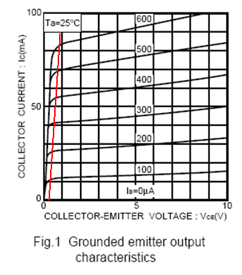 As for MOSFETs, their curves are similar, but the parameters we're looking at different. Here's a set of curves for a N-channel mosfet. 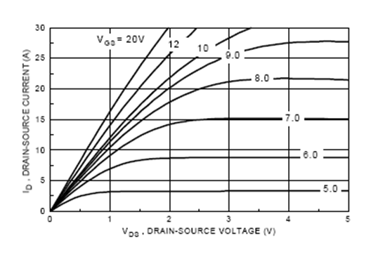 The "output current" on the Y axis is the drain-source current. The "output voltage" on the X axis is the drain-source voltage. Then we have a bunch of curves relating the two, each corresponding to a different input condition, which is gate-source voltage. It's analogous to the BJT curves; just replace base with gate, emitter with source, and collector with drain, and also change base current to gate voltage. Again we can see we have some changes in behavior over the span of our drain source voltage. Towards the right we see that our curves become parallel to the X axis, like they did in the BJT curves, meaning in this region the drain current is controlled primarily by gate voltage. So here we are operating as a voltage controlled current source. Towards the middle of the chart, we see more "knees" in the curves, but they're much less defined than they were for BJTs. They also occur at a much higher drain-source voltage than the BJT ones did. There is actually a fair amount of room to the left of these knees, which is, again, our saturation region. But there's something much different about a FET's saturation region from the BJT's. Too see it, we'll further divide the saturation region into two sub regions. So Here we see the current source region on the right of the parabolic boundaries (interestingly, it turns out these boundaries actually are well defined parabolas) and the two saturation regions on the left.  So on the very left side, we see that our curves are roughly linear. So our drain-source looks like a resistor. And we also see that our curves all have their own slope. Therefore in this region, our FET acts like a voltage controlled resistor! For many purposes this is desirable, and there are a lot of neat things that can be done with it. In general, any FET datasheet will include a plot of the effective drain-source resistance (rds) vs gate voltage. Just keep in mind, that data is only valid as long as you operate within that part of the saturation region. The middle region is kind of useless, since both your voltage controlled current source and voltage controlled resistance assumptions break down. So, when designing, make sure that you are staying in your desired region so your circuit's behavior obeys your assumptions. If you are unsure which region you want to operate in, here are some rules of thumb: 1. For switching, you want SATURATION. This goes for BJTs as well as FETs. For any application where you want to go from completely off to fully on, you want to saturate as much as possible (without killing the input of the devices). Such is the case for low power stuff like making digital logic, or for switching high power loads. It's ESPECIALLY important for power loads so that your output voltage (Vce for transistors or Vds for FETs) is as low as possible. Remember, power is voltage x current, so if your device isn't saturated enough it will heat up quickly. For switching, MOSFETs are generally better because they can saturate easily. 2. For use as an amplifier, you want CURRENT SOURCE. Or, to put it another way, if you want your beta to be predictable and consistent, you want to stay away from saturation (and mosfets have a term similar to beta called gm, or transconductance). Transistors are generally better as amplifiers due to their higher transconductance, though mosfets are sometimes used when you need really high input impedance.
|
|
#
?
Oct 22, 2008 21:22
|
|
|
So, to Sweevo's original question, here's how you go about checking whether a given MOSFET will do the job. 1. Your best gate source voltage will be 12V. So look at the curve for 12V. 2. Now given the current you want, does the 12V curve reach this current inside the saturation region? If so, go to step 3. If not, you've got a problem. 3. Again look at the curves and find the drain source voltage at this point. Is that an acceptable voltage drop? Remember, you want to drop as little voltage across your FET as possible. 4. Find the power it will be dissipating. Is that acceptable? If so, looks like you got a winner. For your specific case, you'll likely need a pretty good FET to deliver most of your power to your load. Standard parts like the irf510 won't do it; it will eat up a good portion of your power. There are tons of parts that will work fine, but you won't likely find them at radioshack. Gate capacitance is not an issue for this application. No AC characteristics will be relevant, since You'll likely be switching very slowly. However, I would add a large resistance from your gate to the source. Like 10K or something. Gate pull down resistors are always a good idea for this kind of stuff, since if for some reason the output of the comparator is disconnected from the FET, the resistor will shut it off. Floating gates are bad news. ANIME AKBAR fucked around with this message at 21:40 on Oct 22, 2008 |
|
#
?
Oct 22, 2008 21:36
|
|
|
That's great stuff. Thanks. So looking at the graphs for something like the IRF540:  5A and 12V is towards the bottom right, so that's well within the saturation region, and I'm good to go?
|
|
#
?
Oct 22, 2008 23:20
|
|
|
reread what I wrote. Start by finding the CURVE (or closest curve) corresponding to Vgs = 12V (one of the upper clump of curves). Then find the point on your curve where Id = 5A. Then trace it down to the X axis to find your Vds. You get around 0.2V, so you get around 98% nominal efficiency and about 1W of dissipation, which is good.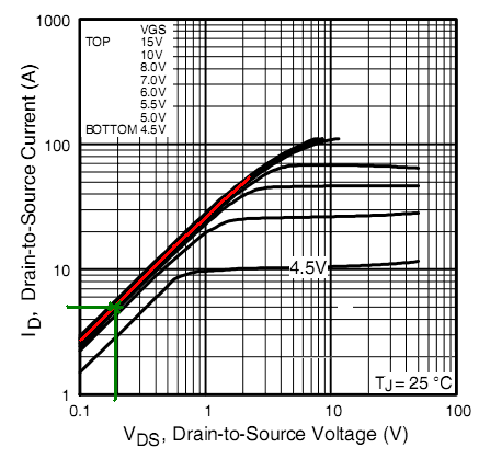 And the saturation region is on the left. Constant current operation is on the right. ANIME AKBAR fucked around with this message at 23:38 on Oct 22, 2008 |
|
#
?
Oct 22, 2008 23:34
|
|
|
Echoing what was said before, I'd recommend separation between the control circuit and drive grounds, as well as a 10K pull-down resistor on the gate. I also think a status LED for the gate voltage and thus drive status would be a good idea. Buffer it through a small n-channel MOSFET connected in the same way as the drive MOSFET, with a resistor in series with the gate, and a pull-down resistor. Put an LED with an appropriate current limiting resistor between the MOSFET and +12V.
|
|
#
?
Oct 23, 2008 01:57
|
|
|
So with a separate ground for the load, a status LED, and pull-downs on the gates I'd end up with this: Click here for the full 826x739 image. (Sorry for all the stupid questions)
|
|
#
?
Oct 23, 2008 12:55
|
|
|
I'm not sure exactly sure what MAH POKEYMANS meant by separating the grounds, but I'm pretty sure that what he's referring to is a design technique sometimes called "star grounding." It's an important thing for any design that involves both sensitive analog and high power systems. Proper supply routing Your power rails (i.e. ground and positive/negative supplies) will never be perfectly low impedances and neither will your voltage sources. Whether you are using ten gauge wire or ten mil pcb traces to distribute power, whether you use a nice switching bench supply or a couple alkaline batteries, you will couple some amount of signal onto your supply rails. And that signal on your supply will be distributed to every circuit it powers, possibly causing big problems. The supply rails can actually act as feedback paths. One of the principle ways to avoid this is the trickiest to explain because it can't really be represented on a schematic, unless we change the schematic to reflect the real properties of the power rail. Consider the case where you have two circuit sections powered by the same source. We draw them as such: 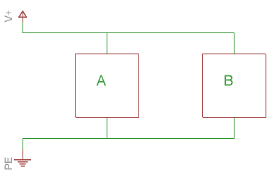 Everything looks fine. But now lets redraw it but put some resistance on the rails: 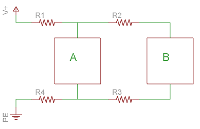 Now we have some potential problems. The current draw from the each of the circuits will cause signals on the rail. Worse yet, the signals from each circuit will be seen by its neighboring circuit. These circuits are now interacting with each other. This happens when circuits are "chained" together; that is they share power rails. Depending on your application, this may not matter. But to reduce this crosstalk, we can do a star ground setup. Here we simply move one of our circuits so that instead of sharing a long length of power rail with the other, they each are supplied directly from the source: 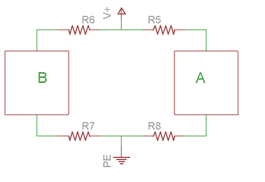 the technique is called star grounding (though it can be applied to any signal, whether it be ground, power, or whatever) because when you have many circuits operating off the same source but each with its own dedicated path to the source, all those traces will converge on a single node placed (ideally) very close to the source itself, looking like a star. Again, this is not represented in the schematic. If we were to take our improved layout and return the power rails to normal it would look like this:  Which is exactly equivalent to what we started out with (at least from the perspective of any layout program, and most engineers). I currently TA an applied circuit design course, and I see the effects of this a lot, because many students will carefully draw up a schematic, sometimes even verify the schematic works via simulation, then build the circuit on a protoboard precisely the same way, but see bizarre behavior. It's because, once again, your models are only as good as your implementation. If they route their supplies through thin traces that wind and weave and supply many devices, they will get crazy poo poo. I've seen oscillation in the tens of megahertz and in the tenths of hertz. I've seen brownout and surges that destroy ICs. I've seen people become hysterical when they see this behavior, and no matter what they try their fancy simulators can't reveal what's happening. I guess that's the difference between scientists and engineers.
|
|
#
?
Oct 23, 2008 20:31
|
|
|
So again, as to your circuit, doing star grounding can't really be shown on the shematic (I guess you could by actually drawing the supply traces instead of using symbols, but that's messy as hell). Just make sure when you actually make it that you separate the supply rail into dedicated paths, one for powering the load and one for powering the op amp stuff, and connect them both directly to your source. The LED stuff looks fine as well.
|
|
#
?
Oct 23, 2008 20:36
|
|
|
Also, adding a few decades of bypass caps (0.01uF, 0.1uF, 1uF) to your IC's VCC pins (VCC->CAP->GND) helps a lot to reduce noise on the supplies.
|
|
#
?
Oct 23, 2008 20:38
|
|

|
Well yeah supply bypassing is a given. A couple small ceramic caps (like 0.1uF) should be fine. Larger values won't matter since your high power load won't be generating any real AC noise, and noise won't effect it either. Bypassing your resister divider outputs might make sense too, but I doubt it will matter at all.
|
|
#
?
Oct 23, 2008 21:59
|
|
|
mtwieg posted:Well yeah supply bypassing is a given. A couple small ceramic caps (like 0.1uF) should be fine. Larger values won't matter since your high power load won't be generating any real AC noise, and noise won't effect it either. Bypassing your resister divider outputs might make sense too, but I doubt it will matter at all. Given that it's a pretty simple circuit that has plenty hysterisis and doesn't need fast edge rates or anything, I don't think he has anything to worry about. Random related fact: If you're putting decoupling caps in, and your circuit is powered via a linear regulator, be careful not to put ceramic caps directly from the output of the regulator to ground. Ceramic caps have way lower ESR (less than an ohm vs. 10-20ish ohms for aluminum electorlytics), and apaprently they end up moving one of the zeroes in the regulators feedback loop and causing oscillations. Actually, I was wondering about something weird that happened at work. I was powering a simple circuit from a 2-prong wall regulator, and scoping it with an oscilloscope that had a 3-prong power plug. When probing the circuit, with the oscilloscope ground clip connected to the circuit ground, I kept seeing 120VAC (inlcuding a one poing with both the probe and ground clip attaching together and to the circuit ground). Connecting the circuit ground to earth ground resolved the problem. I thought that any probed signals were supposed to be refereced to the ground clip, not to earth ground in any way? Or does a mid-range tektronix scope somehow have a CMRR of 0dB?
|
|
#
?
Oct 25, 2008 05:15
|
|


|
SecretFire posted:Given that it's a pretty simple circuit that has plenty hysterisis and doesn't need fast edge rates or anything, I don't think he has anything to worry about. quote:Actually, I was wondering about something weird that happened at work. I was powering a simple circuit from a 2-prong wall regulator, and scoping it with an oscilloscope that had a 3-prong power plug. When probing the circuit, with the oscilloscope ground clip connected to the circuit ground, I kept seeing 120VAC (inlcuding a one poing with both the probe and ground clip attaching together and to the circuit ground). Connecting the circuit ground to earth ground resolved the problem. I thought that any probed signals were supposed to be refereced to the ground clip, not to earth ground in any way? Or does a mid-range tektronix scope somehow have a CMRR of 0dB?
|
|
#
?
Oct 25, 2008 07:26
|
|
|
mtwieg posted:This may be true for some older parts, but nowadays it's the opposite, and most datasheets will specifically recommend ceramics or low-esr tantalums. As long as the capacitance is above some minimum value, the zero moves so far that it cuts the loop gain below unity and oscillation stops. If you use a low esr cap with too small a value, then you might end up with oscillation. I've only observed this on older parts like the 78xx series and the lm317 type parts. Stability issues are quite rare in newer linear regulators, since they're pretty easy to compensate. In this case I was just probing various points on a board with respect to board ground, so you could call the measurements single-ended, but I'd been under the impression before that scopes measured things differentially from ground clip to probe tip.
|
|
#
?
Oct 26, 2008 00:57
|
|
|
Okay, I bet your problem that there's a small break in the probe's ground connection, causing capacitive coupling of the supply voltage into your signal. That's why it disappears when you ground the circuit; you're effectively fixing that connection, though through a different path.
|
|
#
?
Oct 26, 2008 06:53
|
|
|
mtwieg posted:Okay, I bet your problem that there's a small break in the probe's ground connection, causing capacitive coupling of the supply voltage into your signal. That's why it disappears when you ground the circuit; you're effectively fixing that connection, though through a different path. I had that thoguth too, and while I was testing it, I found that the ground clip of the probe I wasn't using (2ch oscilloscope) was broken, but the one on the probe I was using was just fine.
|
|
#
?
Oct 26, 2008 18:21
|
|
|
Ugh, grounding issues are always a pain in the rear end... To rule out the possibility of it being emi, just connect the probe to its own ground. If you still see any signal, it means either a broken connection in the scope/probe or the signal is being induced magnetically. Do a continuity check of the ground connections on your two channels. If they're shorted, then they're single ended (not pseudodifferential, as I said before. Psuedodifferential is different, my mistake). This is, in my experience, the most common configuration. It means you can measure potential between any two points, but the point that the ground clip is connected to will be connected to earth ground. This means that if your circuit doesn't already have an earth ground connection you can do pseudodifferential measurement**. Otherwise you can only clip the ground clip to the circuit's earth ground (since attaching it anywhere else would short it to ground). **Also, if you use two channels on a single ended scope the ground clips of each probe must be on the same signal/potential. Again, otherwise you will be shorting the two points together. That's why it's in some circumstances single ended inputs can function as pseudodifferential inputs. The ground clip connection will be a low impedance, but as long as that's the only low impedance connection then you can make the connection on any point in your circuit, allowing you to use any point as a reference. here's a decent article on the stuff: http://www.maxim-ic.com/appnotes.cfm/an_pk/1108 tell me what you observe (a model number for your scope would be good too) and we can go from there. I see problems like this enough that I'll probably ask some of my professors about it.
|
|
#
?
Oct 26, 2008 18:37
|
|
|
navi posted:I'm working on a project that uses different leds at the same time. 
|
|
#
?
Oct 27, 2008 14:59
|
|

|
navi posted:can anyone help me with this? Im pretty stuck. Do they need to all be on at once? You could run them all in parallel, just use a different resistor for each group. I.e. the blue LEDs would need to drop 1.5v across the resistor and draw 175 mA. This gives a resistor value of around 8.6 ohms which would need to dissipate a little more than 0.25 watts. The red LEDs might be able to wired up at two in series then put those two in parallel. This would give a total drop of 5v. Although you this seems like you wouldn't need a resistor, its always a good idea to include a small value in case your power supply is not exact. Say 1 ohm. How long does this need to run? All of these LEDs are going to draw some power, and I don't think that you'll get much more than an hour or so out of 4 AAs. edit: here is what I mean: 
SnoPuppy fucked around with this message at 17:17 on Oct 27, 2008 |
|
#
?
Oct 27, 2008 16:56
|
|
|
SnoPuppy posted:Do they need to all be on at once?  35A should be 35mA oops 35A should be 35mA oops it would need to run for a couple of hours, maybe 4 per full charge. navi fucked around with this message at 19:15 on Oct 27, 2008 |
|
#
?
Oct 27, 2008 18:43
|
|
|
I'm just getting into this stuff and have found that google is less useful when you don't know exactly what your looking for. So, a couple newbie questions: I have two audio signals. They are currently routed to two separate 1/4" jacks. I want use a single 1/4" jack and a "balance" potentiometer between them. That is, all the way right is one signal, the notch in the center both signals equal, and left the other. Is there a particular potentiometer that allows for this (hopefully with a mouser part no)? Or will I have to build a separate circuit for it? The source of these signals will also be where the jacks are mounted (the inside of an NES). Right now, the grounds on the two 1/4" jacks are being electrical taped to the metal chassis. What would a better way to do this be? Is there something I should look for on the PCB itself that indicates "ground" and would be good to solder to? Sorry about the totally lame questions, though I'm sure I'll have more. I've been wanting to get into this stuff for a long time but I don't know anyone else who is, so I'm starting simple. Thanks!
|
|
#
?
Oct 27, 2008 18:51
|
|

|
kaptainkaffeine posted:I have two audio signals. They are currently routed to two separate 1/4" jacks. I want use a single 1/4" jack and a "balance" potentiometer between them. That is, all the way right is one signal, the notch in the center both signals equal, and left the other. Is there a particular potentiometer that allows for this (hopefully with a mouser part no)? Or will I have to build a separate circuit for it? quote:The source of these signals will also be where the jacks are mounted (the inside of an NES). Right now, the grounds on the two 1/4" jacks are being electrical taped to the metal chassis. What would a better way to do this be? Is there something I should look for on the PCB itself that indicates "ground" and would be good to solder to? As for soldering it, do it somewhere on the PCB, preferable on the thick ground trace close to the power supply. If possible you might want to take a picture and post it for reference.
|
|
#
?
Oct 27, 2008 21:03
|
|
|
navi posted:Would this work? You need to have 3.5v across the blue LEDs and 2.5V across the red LEDs - your design has two red LEDs in series (~5v drop) connected in parallel with the blue LEDs(3.5v). This would either overload one or underload the other - neither is what you want. In the schematic I posted, each group of LEDs has their own voltage dropping resistor for this reason. Regarding the power issue, it really depends on your batteries. Since you aren't using any switching power supplies, a lot of power is being burned in the resistors. The LEDs are going to have a fixed current for a fixed voltage - using a higher voltage only means you are burning more power in your resistors. Ideally you want a power source that can be set to exactly what the LEDs need (very little wasted power). Now that I think about it, since you have 4 AA batteries you could generate 2 voltage rails (a 3v and a 4.5v rail) and use those to power the red and blue LEDs. The downside is that the batteries will discharge at different rates, but it would be more efficient (it would also change the circuit). Do you know how much charge your batteries can provide? This will let you figure out an approximate running time.
|
|
#
?
Oct 27, 2008 21:56
|
|
|
in general for driving LEDs you can't get good efficiency without switching drivers or supplies. Unless efficiency is very important it's not worth the extra trouble. edit: with four AA batteries you're probably get something in the ballpark of eight or nine hours, depending on frequency and battery capacity (I assumed 2000mAh). ANIME AKBAR fucked around with this message at 23:20 on Oct 27, 2008 |
|
#
?
Oct 27, 2008 23:12
|
|
|

|
| # ? May 21, 2024 16:08 |
|
|
mtwieg posted:this is pretty much exactly what nearly all potentiometers do. They have two end terminals with a fixed resistance between them, and one wiper terminal which connects somewhere between the two end terminals, thus giving you an adjustable voltage divider. Just connect your signals to to the end terminals and the balanced output will be at the wiper. That makes a lot of sense. Is there a standard ohm rating that's used for this kind of thing? There's some cool slide pots on mouser (some with leds, though I'd have to figure out how to get power to them) that range from 1k to 100k and up. edit: I don't know how much voltage each signal is, but I can check later. Also, would an audio taper work more effectively here than a linear? I thought linear at first because I just want to control the mix, not the volume, but after a little reading I'm not so sure they're different. edit today: So I was thinking about it and it occurred to me that a linear pot would not simply have the 'middle' as equal and attenuate either signal when it's turned, but rather would attenuate both signals by half, and when turned would both boost one signal and attenuate the other till one is twice as loud (edit again: twice the voltage, a log taper pot would be twice as loud) and the other is gone. Is this accurate? I'm waiting for parts to come in so I can't test it. kaptainkaffeine fucked around with this message at 19:13 on Oct 28, 2008 |
|
#
?
Oct 28, 2008 00:23
|
|