|
senduit.com? There are tons of ways of putting up somewhat large files. A goon works on it too, I believe.
|
 #
?
Dec 16, 2008 06:44
#
?
Dec 16, 2008 06:44
|
|


|

|
| # ? May 8, 2024 10:40 |
|
|
I just bought an hp 1222a oscilloscope and it didnt come with a power cord. The socket for the cord fits a standard pc cord, is it safe to assume that would be the right cord?It also has a two switches for the line voltage they look like thispre:
               Line Select
                240 120
                  |-|
                  | |
                100 220
                   V
                200 220
                  | |
                  |-|
                100 120
|
|
#
?
Dec 18, 2008 22:49
|
|

|
jeremiah johnson posted:I just bought an hp 1222a oscilloscope and it didnt come with a power cord. The socket for the cord fits a standard pc cord, is it safe to assume that would be the right cord?It also has a two switches for the line voltage they look like this I would expect that that cord should be just fine. It's a pretty long-running standard. As for the switch, that's a little confusing. Are you sure either the 240 shouldn't be 200, or the 200 shouldn't be 240? The only way I could make sense of it is if, for example, instead of 200 it said 240 on the lower switch. Then the combination of switches would specify the line voltage. For example, top switch down + bottom switch down = 100. Top switch up + bottom switch down = 120. Etc.
|
|
#
?
Dec 19, 2008 00:39
|
|

|
Corla Plankun posted:My radio got stolen a while back, and I really miss it. I'm not keen on just replacing it with a new one, because it will probably just get jacked again. It's almost that simple. The worst part of it will be running power for the amplifier. Since most separate power amplifiers draw a lot more current than your average head-unit, you won't likely get away with powering it off of the existing wiring for the stereo. You'll need to run a heavier gauge wire from the battery into the car, and another one to a good chassis ground. You'll want to put a fuse inline as well. You'd also need to wire up 12V (via a toggle switch or you can just use the switched 12V lead that used to go to the radio) to the remote turn-on lead of the amplifier. Once that was sorted, all you'd need is a 3.5mm stereo miniplug to RCA adapter to plug it in. The only problems I see with this setup is that, unless your MP3 player has really good bass/treble controls, you might find the system doesn't sound nearly as good as your old stereo did. In my experience, the range of adjustment of most MP3 players is pretty limited, while a head unit needs to be very adjustable because it's designed for an environment that has a lot more variables in it than would a set of headphones coupled directly to your ears.
|
|
#
?
Dec 19, 2008 01:04
|
|
|
thepartypooper posted:I would expect that that cord should be just fine. It's a pretty long-running standard. Oops it does say 240 instead of 200. Thanks.
|
|
#
?
Dec 19, 2008 01:06
|
|
|
I'm sure there's an obvious guide to this somewhere, but how do I know what transistors to use  There's like a million different ones, and I have no idea why you'd choose a 2N5886 instead of a MJ15022 or what the difference even is. How do you know which transistor is suitable for which application? Is there even a concise guide somewhere, or do you just poke through Mouser for one that fits your specs? edit: Let it be known that I know very little about transistor design. I read the tutorial on op-amps a while back and that's about it.
|
|
#
?
Dec 23, 2008 00:51
|
|

|
Paul MaudDib posted:[...]or do you just poke through Mouser for one that fits your specs?[...] Unless its for RF passive parts, this is pretty much what I do.
|
|
#
?
Dec 23, 2008 00:53
|
|

|
Paul MaudDib posted:I'm sure there's an obvious guide to this somewhere, but how do I know what transistors to use It all comes down to knowing what you want to do with one, and reading it's data sheet. For instance, here are four popular NPN transistors: 2n2222A 2n3904 BC337 BC337 Some common specs to look out for (BJT): Max. Collector Current (IC) - Basically how much current you can draw through the transistor. Usually you want far less than that. Make sure you're not exceeding the max. power dissipation the transistor (or rather, it's case and heatsink) can handle. Max. Collector-Emitter and Collector-Base Voltage - At what point the transistors start breaking down. Even if the current is kept low, going to voltages above these levels can permenately damage or destroy the transistors. Make sure you have some safe margins with these values. hFE or DC Current Gain - How 'sensitive' the transistor. Basically, the ratio of how much current is drawn through the collector vs. how much current is drawn through the base, while the transistor is in the active region. Higher values are best for really sensitive amplifiers, like say for thermocouples or passive microphones. DO NOT rely on this value for making circuits, as the value listed is prettymuch an average value. The actual value can vary a whole lot over temperature or even imperfections in manufacturing. (This is why most good electronics textbooks tell you to use negative feedback-based amplifiers instead of straight common-emitter or common-base amps, as their gain is reliant on much more accurate passive components.) However, a transistor with a gain of 20 is not going to be able to get you a gain of 50 no matter how many passive devices you add (unless you do something really, really crazy). So keep this number higher than what you need, especially for common-collector or common-base amps. It's always easier to add in feedback and lower the gain than it is to run the thing wide-open and tear your hair out because it performs like crap. Vbe or Base-Emitter Voltage - Set voltage between base and emitter, as the base and emitter appear to be connected by a diode. Is almost always 0.7V, if the transistor is silicon (99% of the time). It can vary over temperature though, and a datasheet can tell you how badly (not something to worry about unless you have problems with it). Current-Gain Bandwidth Product or fT - Basically what kind of useful gain over what frequencies you can get. If you're trying to amplify a 100MHz signal, for instance, a 3904 will get you a gain of ~3, as it's GBP is 300MHz. The same transistor with a 1MHz signal can get you a gain of 300. Note that this effect is limited by the transistor's DC-current gain, so in the 3904 the gain cannot go above ~300 (so don't expect super-high gains at low frequencies). If the gain drops below 1, then it's time to look at another transistor (I'd keep it as high as possible personally, unless you want to use jellybean transistors, as high gain = less distortion in negative-feedback amplifiers and any feedback-based circuit). Cuttoff Currents - The currents at which the transistor slip into cutoff mode. Basically the transistor doesn't work (behaves as two diodes) below this point. Important to pay attention to if you plan on making things battery-powered or low-power. Small signal transistors like the 3904 have very low cutoff currents, in it's case 50nA. Large transistors like the 3055 have higher cutoff currents, in it's case nearly 5mA through the emitter (so base+collector). Max. Power Dissipation - How much power can this thing take before it melts? A 3904 can take a puny 625mW before the magic blue smoke is released. A 3055 on the other hand, can take a whooping 115 watts before biting the bullet. Keep in mind you may have to sink all of that heat from the device for it to continue to operate at that point. With a 3904 the case itself is fine, but a 3055 will probably need a huge heatsink. Rise/Fall/Storage/Delay Time - The time it takes the transistor to go through the various parts of a square wave. Important if you are using the transistor in a switching application (as opposed to an amplifier or as some sort of signal modifier). FET Replace Collector with Source, Emitter with Drain, and Base with Gate, and you have a FET. All of the same above apply, except Vgs voltage works differently (no 'diode'). Max Vgs - In a FET, there is no diode separating the gate from the source (only a 'capacitor'), so you're free to set that voltage too. There is a max. voltage between the gate and the source you can have though. Generally it's wise to stay within that range, although some FETs can take the abuse if you choose to go over (just don't blame me when blue smoke pours out of the thing). Drain to Source resistance - A lot of power FETs have this rating. Basically how low to expect the resistance to be between drain and source when the transistor is 'full on'. Most FETs are used like switches anyhow, so that's a good figure to know. As general rules of thumb: -Small Signal BJTs are often interchangeable. I know I've found 3904 and 4401 transistors lumped in with 2222A transistors (annoyingly enough). They do tend to differ in maximum current vs. speed. A 4401 can sink nearly 600mA of current, while a 3904 can only sink a paltry 200mA. So watch out if you're designing radio components or driver circuits (a headphone amp I made recently works with 2222As or 4401s, but not 3904s because the application draws too much current...and even 2222As are a bit underpowered). -Quality tends to shift around a lot on the very popular transistor types, so either find a reputable vendor/manufacturer or consider their data sheets overrated. -Power BJTs aren't used as much anymore commercially, but you can find 2n3055s and 2955s EVERYWHERE. They're not very fast, but they tend to work alright for switching moderate currents and as high-power output stages, and they're rugged as hell. -Power FETs are pretty fast, and can switch very large current loads. Use em as power switches, or as part of that Tesla coil you want to build. Many power FETs tend to have a diode between the source and drain as a safety. -Note that the case of a transistor has a lot to do with it's power dissipation. A TO-92 case, for instance, can only dissipate about 625mW of power. Any more and you can get the transistor too hot and damage it (I'd stay below that number). A TO-3 case or a TO-220 case you can hook to a heatsink and push the transistor to it's limits (and then boil some water with the nice space heater you've made yourself). Common Transistors: NPN: 2n2222/A - Seen everywhere, average at prettymuch everything. 2n3904 - Low power, can't take much abuse but works at high frequencies (up to 300MHz). Tends to be very popular for hobbyists, and is also seen everywhere. 2n4401 - Slower speed, can sink more current (but not more power). 2n3055 - Big old sucker, use for high-current applications. PNP: 2n2907 - Compliment to the 2n2222, probably the most popular small PNP. 2n3906 - Compliment to the 2n3904, fast and low-current. Also seen everywhere. 2n4403 - Compliment to the 2n4401. 2n2955 - Compliment to the 2n3055. Not quite as common as the 2n3055. Prettymuch any 74xx TTL chip (without a 'C' designator), older chip, and a good number of analog chips use BJTs either exclusively or in combination with FETs. FETs have all but totally replaced BJTs for digital circuits, and are quickly taking ground on the Analog side. Most discrete transistors are either high-power FETs or BJTs of all types. FET: IRF540 - Pretty common high-power FET. Often a better choice than a 3055, but more expensive. HEF4007 - Small-signal FETs on a chip, if you want to play around with those. Almost every modern IC you'll probably be using, including prettymuch any microcontroller, uses FETs exclusively. IGBTs: Don't know of common types off the top of my head. Use them when you need to switch gobs of current. Like, a camera flash, a super tesla coil, or half the freaking power grid. Also, Toshiba seems to like using them for power amplifiers (they can run really cool). clredwolf fucked around with this message at 06:45 on Dec 23, 2008 |
|
#
?
Dec 23, 2008 06:00
|
|

|
Also I need to clean up that OP, but drat there's a lot of new information to shift through. Think I should keep it the same, or would it really be that beneficial to have a good table of contents?
|
|
#
?
Dec 23, 2008 06:59
|
|
|
Does anyone know if there is an IC that's essential function is to generate random numbers? My girlfriend is always asking me to "pick a number between 1-10" to help with decision making and I would love to make a little fob that produces a random number at the push of a button. I can wire everything else, including a small liquid crystal panel, but no idea on the number generation.
|
|
#
?
Dec 24, 2008 07:34
|
|

|
kaishek posted:Does anyone know if there is an IC that's essential function is to generate random numbers? My girlfriend is always asking me to "pick a number between 1-10" to help with decision making and I would love to make a little fob that produces a random number at the push of a button. I can wire everything else, including a small liquid crystal panel, but no idea on the number generation. There's no such thing as a random number generator but you can approximate randomness fairly easily by using a decade counter IC for a range of 0-9. Rig it so it counts up very quickly and stops (or stores the current number with a latch) when you press a button and then display it. Since you can't see the counter's number until you press the button, it may as well be random. Edit: A lot of microcontrollers have timers that can be used like that if you have any experience with those, and the Z80 CPU has a DRAM refresh register that can also be abused in a similar way. BattleMaster fucked around with this message at 07:52 on Dec 24, 2008 |
|
#
?
Dec 24, 2008 07:43
|
|

|
The decade counter is actually pretty much perfect. Some applications show a 555 being used to time its outputs which will work in the background with no display...so ideally the push of a button would disconnect the 555 pulse (so it stops counting) and connect the output of the counter to an LCD single digit display.
|
|
#
?
Dec 24, 2008 08:17
|
|
|
BattleMaster posted:There's no such thing as a random number generator Yes, there is. Here is one: http://www.fdk.com/cyber-e/pi_ic_rpg100.htm Like battlemaster said, if you are using a uC and will be pressing a button or something, you can easily take the low bits of a running counter. It will be random because it will have been operating an unknown amount of time before the button is pressed. If you need a larger value, you probably want to look into pseudo random number generator algorithms, which will be just fine for a "give me a number between x and x" type application. Another possibility is measuring some external input and only keeping the noise. Something like a thermistor into an ADC or maybe just a floating ADC. You would need to use an algorithm to collect entropy. The linux kernel does this and you could steal the code from there. There are apps for the PC that do this using the sound card. e: Here is a guy's project that might be helpful: http://www.cryogenius.com/hardware/rng/ taqueso fucked around with this message at 08:47 on Dec 24, 2008 |
|
#
?
Dec 24, 2008 08:38
|
|


|
taqueso posted:Yes, there is. Here is one: http://www.fdk.com/cyber-e/pi_ic_rpg100.htm Oh, neat. That is a bit complicated for something basic like this though. Is that kind of thing actually as reliable as it says it is? Anyways if you're going to use a 555 timer and decade counter you should use a latch to hold the current number instead of just stopping the clock. I think it would simplify the circuit. Something like this:  I couldn't be assed to hook up the 555 timer and I swear Eagle doesn't have a basic pushbutton part (pretend there's one between the +5V and resistors), but the rest of it should be okay. Edit: If your LCD is similar to a seven-segment display rather than pixels you can toss in a BCD to 7-segment decoder and you'll probably have a complete circuit. BattleMaster fucked around with this message at 19:59 on Dec 24, 2008 |
|
#
?
Dec 24, 2008 08:47
|
|
|
I'm planning on making an iPod line-out / charging mount for my car, like a poster earlier in this thread. pinouts.ru has got me to the point where I know I can do the simple wiring involved, but then I discovered the Apple Accessory Protocol and my poor addled brain has started having Ideas. I would be tickled to build an iPod controller into my dashboard, but it occurred to me that I have no idea how to do serial communications on an embedded level. I'm used to memory mapped devices. "Write 0x1F230CD6 to memory location 0x0810," that sort of thing. I guess the actual hardware latches the value, maybe? I suppose having a Arduino-based solution would be the easiest on me so I don't have to build dedicated hardware, but that might be cool too. Any pointers on what I need to learn do to serial communications on this sort of level? ")
|
|
#
?
Dec 25, 2008 20:37
|
|

|
I don't think you need to bother with AAP if you just want charging and line out.
|
|
#
?
Dec 25, 2008 22:52
|
|

|
You don't need to communicate with an iPod it to charge it or else MintyBoost wouldn't work. If you really want to play with it, a glance at that page tells me you can use the UART (standard serial port) on a microcontroller running at 19200 baud with 8 data bits, no parity bit, and 1 stop bit to send or receive data from a device using AAP. The ATMega microcontroller on the Arduino board (The Arduino is not a microcontroller, dammit!) definitely has a UART so you won't have any problems if you go that route. Using a UART is just like any memory-mapped peripheral, really. You toss the byte you want to send into a holding register and then watch a status register to find out when it's finished and ready to transmit another byte. Receiving is pretty much the same in reverse. If you're using C there's likely a ready-made library that does it all for you. Be sure to check the datasheet or manual for details. BattleMaster fucked around with this message at 23:29 on Dec 25, 2008 |
|
#
?
Dec 25, 2008 23:15
|
|
|
What's a good (and kinda cheap) power source for this breadboard for a beginner. I can't afford, nor really utilize, a $200 fancy unit. http://www.jameco.com/webapp/wcs/stores/servlet/ProductDisplay?langId=-1&storeId=10001&catalogId=10001&productId=194272&
|
|
#
?
Dec 26, 2008 04:12
|
|
|
the wizards beard posted:I don't think you need to bother with AAP if you just want charging and line out. BattleMaster posted:You don't need to communicate with an iPod it to charge it or else MintyBoost wouldn't work. Well of course, that would be really stupid on Apple's part. Like I said I'm interested in building a controller. BattleMaster posted:(The Arduino is not a microcontroller, dammit!)  quote:Using a UART is just like any memory-mapped peripheral, really. You toss the byte you want to send into a holding register and then watch a status register to find out when it's finished and ready to transmit another byte. Receiving is pretty much the same in reverse. If you're using C there's likely a ready-made library that does it all for you. Be sure to check the datasheet or manual for details. This gives me pause: http://arduino.cc/en/Reference/SoftwareSerial - it sounds like the API has some serious drawbacks. Would a different platform be a better way to go?
|
|
#
?
Dec 26, 2008 05:15
|
|
|
csammis posted:I never said that it was That wasn't really directed at you, and sorry if it came across as being a bit nasty. I just like to make sure people know that they're working with an ATMega168 AVR microcontroller on a board called the Arduino. I think people would learn more if they knew to look up information on AVR microcontrollers rather than limiting themselves to the range of Arduino tools and documentation. quote:This gives me pause: http://arduino.cc/en/Reference/SoftwareSerial - it sounds like the API has some serious drawbacks. Would a different platform be a better way to go? That's a library that uses software routines to create a serial signal rather than using the built-in hardware. The ATMega168 on the latest Arduino boards definitely has a hardware UART so I don't know why there doesn't seem to be a library for using it. I don't think it's a lost cause, though. You can probably make your own solution by "manually" loading registers rather than relying on library functions. I wish I could help you more but I have way more experience with PIC and Z80 than AVR. Edit: The Arduino boards label the UART pins as TX and RX so they seem to intend for you to be able to use it. Edit 2: This page lists hardware serial output functions. I don't know why it's stashed with the "language reference" rather than the library reference though. Edit 3: I edit too much BattleMaster fucked around with this message at 06:09 on Dec 26, 2008 |
|
#
?
Dec 26, 2008 05:51
|
|
|
csammis posted:This gives me pause: http://arduino.cc/en/Reference/SoftwareSerial - it sounds like the API has some serious drawbacks. Would a different platform be a better way to go? That's a library designed to use more than two pins for serial communication. You'd wire up the Arduino according to this, connecting each Tx and Rx pin to each other. Because of that, you wouldn't have to use that library, so you'd have none of the associated drawbacks. Use this instead. Arduino will work fine for your project.
|
|
#
?
Dec 26, 2008 06:19
|
|

|
Penfold posted:Ok, I have a bunch of disposable camera flashes I want to discharge at the same time. On ring flashes, we have an even more ghetto solution kicking around the office: a black matboard box with a cardboard tube in the middle, with the space between lined with tinfoil in a decent approximation of a sliced-bagel shape, and a rectangular cutout in one edge for the speedlite. Judging from the fading of the matboard and the size of the tube, it's left over from the film days. quote:By the way, one of those capacitors hurts like gently caress all when they blow on the back of your hand (and they make a sound like a screaming woman, that might have been me though) I shorted a one-use-camera flash with a Swiss Army knife once, just for the hell of it. There's a notch in the blade where it arced and melted the steel. Don't gently caress around with capacitors, kids. And now for something completely different: I have a Big Red Button with a covered arming switch (a friend that works at the electronics version of an army surplus store abuses the employee discount for my benefit). What should I use it for? Thermite on the HDDs? "gently caress you" hard-reset switch on my computer? Toss a couple of high-amp batteries in the box and make a general-purpose detonator (and dig out my old model rockets)? The first option is a no-go, because of the temptation to push it. What's a good battery for the all-purpose detonator? I'm thinking a pair of 6v lantern batteries -- it's currently installed in the lid of a Radio Shack project box, so they should fit, though there is the comedy option of a 20-pack of dollar-store carbon-zinc AAs. If I do go the detonator route (with a few big batteries), I'm planning on wiring up a switch to pick between series and parallel on the batteries; is this possible?
|
|
#
?
Dec 27, 2008 08:50
|
|
 Bad Angus! Bad!
|
Delivery McGee posted:If I do go the detonator route (with a few big batteries), I'm planning on wiring up a switch to pick between series and parallel on the batteries; is this possible? Absolutely. Here you go:  Someone else should probably check this to make sure I'm not shorting anything out by accident. It's late and I'm tired. Oh also, that's a single DPDT switch in there.
|
|
#
?
Dec 27, 2008 09:32
|
|

|
Mill Town posted:Absolutely. Here you go: Looks good to me, but I'm no EE. I think I have one of those switches kicking around somewhere. Actually, I think I've already got it in the box, along with a single-thingy switch (like I said, I'm not an EE) to select between one/both batteries. Now I just need to work out the actual installing the batteries part. Edit: Edit again: following lines is hard. Chillbro Baggins fucked around with this message at 12:20 on Dec 27, 2008 |
|
#
?
Dec 27, 2008 09:55
|
|
|
No, looks good to me.
|
|
#
?
Dec 27, 2008 10:57
|
|
|
e: okay thanks, I'll make the thread in a minute e2: thread is here ANIME AKBAR fucked around with this message at 22:37 on Dec 27, 2008 |
|
#
?
Dec 27, 2008 21:37
|
|


|
mtwieg posted:Okay I set up a filer account and I uploaded the technical report of my SODAR project. Before I make the thread on it I wanted to make sure I've got the hosting set up right. So just let me know whether this link works or not (should go to a pdf of the report). Works fine.
|
|
#
?
Dec 27, 2008 21:53
|
|
|
Delivery McGee posted:And now for something completely different: I have a Big Red Button with a covered arming switch (a friend that works at the electronics version of an army surplus store abuses the employee discount for my benefit). What should I use it for? Thermite on the HDDs? "gently caress you" hard-reset switch on my computer? Toss a couple of high-amp batteries in the box and make a general-purpose detonator (and dig out my old model rockets)? Holy poo poo, I want one of those. I wouldn't even know where to start looking for a store like that in Canada though. I don't build model rockets, but I'd start if I could launch them with something like that. I'd probably just go the cheaper route and dig out a PIC18F4550 and make a USB panic button, though. BattleMaster fucked around with this message at 01:10 on Dec 28, 2008 |
|
#
?
Dec 27, 2008 22:46
|
|
|
There are plenty of hole in the wall electronics stores around if you know where to look. Just through asking around, I've found five in Vancouver, all good for different things. One has walls covered in switches like those mentioned above, one has dirt cheap resistors, one has all the CMOS chips I need, that kind of thing.
|
|
#
?
Dec 28, 2008 00:55
|
|
|
Just thought I'd throw this out there to all the other electronics beginners like myself; The National Programme on Technology Enhanced Learning has a shitload of 1hr electronics lectures on youtube, 40 or more of them, going from very basic to advanced. They've been really good so far. The very first one http://www.youtube.com/watch?v=w8Dq8blTmSA
|
|
#
?
Dec 28, 2008 19:50
|
|
|
BattleMaster posted:Holy poo poo, I want one of those. I wouldn't even know where to start looking for a store like that in Canada though. Like ante said, any decent-sized city should have some kind of hole in the wall, or at least an electrician's supply house. Flip up the cover, flip the switch under it, and the big button lights up, then press it to fire ze missiles/release the hounds/destroy the evidence/etc. Total cost of all parts shown (it's empty inside for now): $15 or so. The big button alone costs that much on the internet. 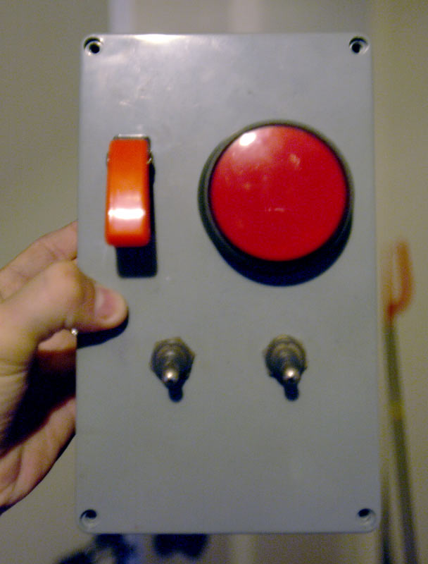
|
|
#
?
Dec 30, 2008 00:09
|
|
|
Delivery McGee posted:Like ante said, any decent-sized city should have some kind of hole in the wall, or at least an electrician's supply house. Depends where you are in Canada, though. Canada is loving huge. I can tell you where to find such things in Halifax, Montreal or Toronto. Are you anywhere near any of those places, BattleMaster?
|
|
#
?
Dec 30, 2008 00:53
|
|
|
Mill Town posted:Depends where you are in Canada, though. Canada is loving huge. I can tell you where to find such things in Halifax, Montreal or Toronto. Are you anywhere near any of those places, BattleMaster? Awesome, I thought it was going to be hopeless to find something like that because Delivery McGee said his was military surplus. All the "military surplus" stuff we have here is stolen, fake, or pre-Korean War. Anyways, I'm close enough to Toronto that it wouldn't be a big deal to make a trip one day. Thanks!
|
|
#
?
Dec 30, 2008 02:08
|
|
|
BattleMaster posted:Awesome, I thought it was going to be hopeless to find something like that because Delivery McGee said his was military surplus. No, I meant the shop has the same sort of business model as an army surplus store -- they get random salvaged/overstock electronics stuff from everywhere.
|
|
#
?
Dec 30, 2008 05:00
|
|
|
Delivery McGee posted:No, I meant the shop has the same sort of business model as an army surplus store -- they get random salvaged/overstock electronics stuff from everywhere. drat, I thought you got an authentic Big Red Button from a Titan missile base or something.
|
|
#
?
Dec 30, 2008 05:48
|
|
|
BattleMaster posted:Awesome, I thought it was going to be hopeless to find something like that because Delivery McGee said his was military surplus. All the "military surplus" stuff we have here is stolen, fake, or pre-Korean War. OK, what you want to do is head down to Active Surplus. I can't guarantee that they'll have the big red button, but they will have a nice assortment of similarly awesome things.
|
|
#
?
Dec 30, 2008 08:48
|
|
|
The electrical supply house has those buttons, too. I know because we had to get 8-10 of them for the current job. Red 2.5" Round Mushroom-head Momentary Contact switches labelled "emergency stop." They're stocked parts. Same way with Red Guard SPDT Toggle. You can also get wierd toggles there, with or without guards. Single and double-pole, double- or triple-throw (up momentary, on, of; think ignition switch, but a toggle). They even have a really cool section for "stackable" switches, where you have one "operator" rod, and stack contacts behind it. So you have a keyed (or flange, or mushroom or whatever) switch on top, then NO/NC, NO, NC, etc modules that all click together behind it for multiple throws and poles. I think the ones I saw were made by Cooper Wiring Devices and were only a couple of bucks per module.
|
|
#
?
Dec 30, 2008 13:29
|
|

|
Mill Town posted:OK, what you want to do is head down to Active Surplus. I can't guarantee that they'll have the big red button, but they will have a nice assortment of similarly awesome things. they do but they don't have backlights for the massive ones. Last time I checked they had sold most of the red ones. Funnily enough active surplus has a bunch super cheap of left over russian military surplus helmets from halloween. Mozzie fucked around with this message at 03:15 on Dec 31, 2008 |
|
#
?
Dec 31, 2008 03:10
|
|
|
Grand_High_Took posted:some stuff on the previous page re background for what I'm trying to do I'd like to build a small and easily concealed electromagnet in order to trigger the induction based detector that sends a "car exiting" signal to the gate outside my apartment. The gate system is manufactured by Elite access systems inc, and the model # is SL-3000-UL. The manual is here: http://www.amazinggates.com/Do_It_Yourself/web/Manuals/Elite-SL_3000-manual.pdf, mostly useful for page 22, which shows a diagram of the induction coil, or loop, or whatever they're calling it. Actually, for those not interested in the whole PDF, here's the picture:  I understand from a neighbor that a bicycle contains enough metal to trigger the thing, so if I can generate the same amount of magnetic fluctuation in the field generated by their coil as is caused by the amount of metal in your average bicycle, that should be sufficient. My question is: how much power do I need for this, and how big is the electromagnet going to have to be? I want to have something small enough that if I paint it black and put it in the driveway with a dollop of tar over it, no one will be very likely to notice its presence. Is this feasible? Any input would be most appreciated. Grand_High_Took fucked around with this message at 09:11 on Dec 31, 2008 |
|
#
?
Dec 31, 2008 09:08
|
|

|

|
| # ? May 8, 2024 10:40 |
|
|
mtwieg - you don't have PMs. Can I get in touch with you somehow about a few questions I had? You can shoot me an email: grantsd AT gmail.com. I had a few questions about the buzzer/locator thing I'm working on and I'd love to talk to you. Thanks!
|
|
#
?
Jan 1, 2009 04:05
|
|