


|
Don't forget the Gaincard. $2300 and it's two ICs from National (lm3875) that's ~$6.30/ea. I don't think it even deviates from the reference design, which is only a handful of components.
clredwolf fucked around with this message at 03:26 on Mar 23, 2009 |
 #
?
Mar 23, 2009 03:20
#
?
Mar 23, 2009 03:20
|
|


|

|
| # ? May 21, 2024 13:07 |
|
|
Speaking of audio fun, here's a small part of my current project: Bonus points for recognizing the boards.
|
|
#
?
Mar 23, 2009 04:41
|
|
|
Since we're talking about exploding capacitors, I guess now would be a decent time to ask if this circuit is going to kill me or not. Someone on another forum was talking about using supercapacitors to keep something running during a power outage. I looked them up and then played around with the idea of a circuit that remains operational for a short time after losing power, so that it doesn't lose data when changing batteries or something like that. Here's what I came up with:  What I'm trying to do is have the capacitor charge when the circuit is powered from an outside source (wall wart, battery, etc.) and discharge when the power is cut. The transistor (or FET or whatever it ends up being) is supposed to cut off ground when the power is removed because otherwise the capacitor would discharge too fast. Will this even work? And is a 5 volt, 0.47F capacitor big enough to harm a human? I don't see any warnings anywhere about it but that's a fuckload bigger than anything else I've used. BattleMaster fucked around with this message at 05:17 on Mar 23, 2009 |
|
#
?
Mar 23, 2009 04:54
|
|

|
BattleMaster posted:Since we're talking about exploding capacitors, I guess now would be a decent time to ask if this circuit is going to kill me or not. I don't know what you mean by discharge too fast. The point is that you want the capacitor to act as the source when Vcc is disconnected, right? So you should just put it in parallel with Vcc. The way you have it drawn there is no return path for current to the capacitor. quote:And is a 5 volt, 0.47F capacitor big enough to harm a human? I don't see any warnings anywhere about it but that's a fuckload bigger than anything else I've used. If it's only charged up to at most 5V you shouldn't be any more concerned about it than any 5V source. Don't lick the leads and you'll be fine.
|
|
#
?
Mar 23, 2009 05:33
|
|

|
BattleMaster posted:Since we're talking about exploding capacitors, I guess now would be a decent time to ask if this circuit is going to kill me or not. I don't think it will work the way you want. When you lose power, the capacitor will attempt to hold the power rail at whatever voltage it was previously at. This will keep your transistor to ground turned on until the capacitor discharges enough to turn the transistor off. Why not just use the capacitor as massive bulk decoupling? As to the safety, it depends on other characteristics of the capacitor - mostly the ESR (equivalent series resistance). This is the internal resistance of the capacitor and will determine how fast it discharges if it's hard shorted. The total energy stored is 0.5 * C * v^2, so for your capacitor@5v, you're only storing around 6 joules. The ESR will determine the RC time constant for a hard short. Now remember, power is a joule/second, so even though its only 6 joules of energy, it can be a lot of power if its delivered in a short time. So lets say that based on the ESR, the time constant is 0.05s. That means you are delivering 120 watts of power, peak! And, if you also remember that P=IV, you can determine the peak current = 24 A. FYI, this is with a completely made up time constant - yours may be much smaller, leading to higher peak currents. Granted the voltage is still fairly low, so it's not that bad if you touch it (your resistance is >> 0 ohms).
|
|
#
?
Mar 23, 2009 05:50
|
|
|
turbo sex bat 4000 posted:I don't know what you mean by discharge too fast. What I meant was that I don't want the capacitor's charge to be pissed away through that 10 Ohm resistor rather than the rest of the circuit, so the transistor is intended to block that off when the power from VCC is gone. But I see now that that wouldn't work, either. Hell the entire thing wouldn't work because as you said there wouldn't be any path back to the capacitor. Whoops! SnoPuppy posted:Why not just use the capacitor as massive bulk decoupling? Does that mean to connect it between VDD and ground? Would that work as intended? Edit 3: Okay, cool. BattleMaster fucked around with this message at 06:00 on Mar 23, 2009 |
|
#
?
Mar 23, 2009 05:53
|
|
|
BattleMaster posted:What I meant was that I don't want the capacitor's charge to be pissed away through that 10 Ohm resistor rather than the rest of the circuit, so the transistor is intended to block that off when the power from VCC is gone. If its a DC load just put it between Vcc and GND and call it a day. Thats what all the 0.1uF caps you see scattered around digital schematics are for.
|
|
#
?
Mar 23, 2009 05:57
|
|

|
hobbesmaster posted:If its a DC load just put it between Vcc and GND and call it a day. Thats what all the 0.1uF caps you see scattered around digital schematics are for. Yeah, it looks like I just massively overcomplicated it. That's what happens if you try to design something without fully understanding it, I guess. I was doing some cool experiments earlier with capacitor charging/discharging and I think I got carried away with that. BattleMaster fucked around with this message at 06:04 on Mar 23, 2009 |
|
#
?
Mar 23, 2009 06:01
|
|
|
More bragging.  That's the circuit my student came up with. And the chip that's just sitting there, well that's my fault. I hooked up the power leads backwards once, and let the smoke out of that 555.
|
|
#
?
Mar 23, 2009 08:52
|
|

|
Aluminum Record posted:Someone also once posted a little project of turning a computer power supply into a bench top hobby supply with a bunch of different outputs. Anyone remember it? I think it may have been posted separate of this thread, probably in the archives by now. Maybe a good reason for me to finally buy access. It's pretty easy. All you have to do in order to get a PC power supply to turn on by itself is short the PS-ON wire to one of the ground wires, then group all of the wires into their different voltages (they're color coded usually). There are some pretty good tutorials online (do a good search for "atx bench supply") about how to do it, but the basic idea is you cut off all the connectors, group together all wires of the same color (there are four colors you care about here), and then short the P-ON wire to ground or maybe put a power switch there. Most ATX power supplies don't have a -5V rail any more, so you usually get: +3.3V (amps and amps of it) +5V (amps and amps of it) +12V (a couple of amps) -12V (200mA or so) It's worth noting that all of these voltage rails are switching rails, so they will be very noisy. You'll want to filter them heavily if you intend to do high-fidelity analog work or something. Also a lot of websites will tell you that ATX power supplies need a minimum load to work, and will suggest you install some power resistors across the 3.3V and 5V rails. This might or might not be part of the ATX specification, but I usually leave those off and it works fine without them. We use ATX power supplies all the time at my work, although they're cheap enough that we usually just put 20-pin ATX connectors on the boards that can fit them, and a custom 2x10 header (used with an adapter cable) on the boards which can't fit a full ATX connector. Since ATX power supplies are dirt cheap (even when they're not free from the IT department) and easy to move around, they're a great solution when you have four or five people each needing to power two or three test boards that need the standard complement of rails. The only difference is we usually have two subregulators on board to step from +/-12V to +/-10V for better noise performance, and we step +/-5 down from those rails if we need it.
|
|
#
?
Mar 23, 2009 10:03
|
|

|
PSU power supply yeah you need to find the datasheet for the power supply, minimum current in order for the supply to regulate the output votltage on mine was ~1 amp on the 12v rail half amp on 5v and I think the same on 3.3. So you need some chunky power resistors, place them in an area where there is high airflow ( glued to the mesh where the air exits is a good idea) the -12v and 5vsb rails didnt need anything on them, make sure you use some chunky wires to the bananna sockets as the thing can deliver some serious power, also remove the soldered in slow blow fuse and replace it with a 500ma 240v ( or 120v I guess) 500mA fast blow ceramic filled fuse, the type used in your multimeter and microwave, they have a mich higher interrupt capacity than your typical glass fast blow and only cost a dollar or two. there is also a sense wire which you will need to connect, teh purpose of this is to sense the voltage at the load to take into account any losses in the cables of the psu. connect this to the appropriate bananna plus as it is what is used to regulat the voltage, the ripple is small enough that it doesnt really have much of an effect on most things, and its a lot cheaper than a proper bench psu I have added a pair of indicator LED's to mine that indicate power on mains and psu OK, short circuits trip the internal breaker and it can be reset by switching the thing on and off ( via the low voltage side ) I added a mains voltage switch as the original PSU lacked one and covered the 5vsb plug with shrink wrap a I dont need it. edit: just checked it 12v 16A rail 12.13v with 4mv ripple 5v 25A rail 5.12v with 3mv ripple -12v 0.4A rail -11.91v with 12mv ripple 3.3v 15A rail 3.37v with 2mv ripple so a decent supply especially, considering I got that psu from a bin at a mates workplace Bush Ant fucked around with this message at 12:41 on Mar 23, 2009 |
|
#
?
Mar 23, 2009 12:30
|
|

|
ANIME AKBAR posted:Overall I avoid using tantalum completely. We have a design standard at work that forbids using tantalums in anything other than well controlled, current limited circuits due to their failure mode of "catch on fire". I just skip them entirely as well.
|
|
#
?
Mar 23, 2009 16:56
|
|

|
Nerobro posted:Uh. Yeah. This is rather tricky. I wish i had some solder paste and a hot air pencil. I probally have it about half done. Do yourself a favor. Pay the $16 to get the assembled version. My time is worth more than $14 an hour, and I've put 90 mins in it so far. Just put a bead of solder on the tip of you iron, what you think would be enough to make the joint. Put your flux precisely where you want the solder, then tap it with your solder bead. It might take more then one tap but it should do the trick. Easier with a hooked tip so you can lay it alongside. edit: I know gently caress all about programming and little about layout, but I am real good at micro soldering.
|
|
#
?
Mar 23, 2009 19:57
|
|

|
Is there any advantage to tantalum capacitors? They sound ridiculously dangerous. I don't understand why they would ever be an option.
|
|
#
?
Mar 23, 2009 19:58
|
|

|
Has anyone used one of the super-cheap PIC programmers from ebay? Something like this, this, or this? I wanted to start playing around with PICs, but didn't want to have to spent �50+ on a programmer.
|
|
#
?
Mar 23, 2009 20:19
|
|


|
Sweevo posted:Has anyone used one of the super-cheap PIC programmers from ebay? Something like this, this, or this? You should look into a debugger instead of a programmer to save a lot of grief when you get into bigger projects. I know for sure that people sell really cheap compatible clones of the Microchip ICD2, so see about getting one of those. The ICD2 can act as a basic programmer until you get a feel for debugging, and as a bonus you don't need to keep popping the PIC out of the board to load new code onto it. Edit: If you still don't care about that, the cheapo �5.99 is adequate unless you really want the USB interface on the more expensive one. Just note that none of those seem to have support for programming directly from MPLAB so be prepared to switch between programs every time you want to program. BattleMaster fucked around with this message at 20:40 on Mar 23, 2009 |
|
#
?
Mar 23, 2009 20:34
|
|
|
Corla Plankun posted:Is there any advantage to tantalum capacitors? They sound ridiculously dangerous. I don't understand why they would ever be an option. They usually aren't unless you're running high levels of power through them. They have a lot of capacitance for a pretty small area, and they're used a ton in SMD boards for that reason. Also some audiophiles have hard-ons for them, but well lemme tell you a story about audiophiles... Oil-filled caps can catch fire too. Aluminum electrolytics burn too, and are hilariously fun to microwave.
|
|
#
?
Mar 23, 2009 20:49
|
|
|
And.... what's the story :-) and who's going to host the site so we can start raking in cash? I'll buy the domain.
|
|
#
?
Mar 23, 2009 20:55
|
|
|
Corla Plankun posted:Is there any advantage to tantalum capacitors? They sound ridiculously dangerous. I don't understand why they would ever be an option. package density, pretty much. They're inferior to electrolytic in pretty much every other way. Unless you're designing something that absolutely needs to be small, they're pretty much worthless.
|
|
#
?
Mar 23, 2009 21:09
|
|


|
clredwolf posted:They usually aren't unless you're running high levels of power through them. They have a lot of capacitance for a pretty small area, and they're used a ton in SMD boards for that reason. Pretty much this. You can get a 100uF tantalum cap in an 0805 package. The smallest ceramic is like 1206. An electolytic would also be fairly bulky as well. Tantalum also has a much higher ESR than ceramics and electrolytics, which can be advantageous for power supply stability (or so I'm told).
|
|
#
?
Mar 23, 2009 21:32
|
|
|
Sweevo posted:Has anyone used one of the super-cheap PIC programmers from ebay? Something like this, this, or this? I totally recommend doing it right from the start and get a nice solution. I bought a Pickit 2 after getting frustrated with my serial programmer and haven't looked back. The in-circuit programming is worth it, along with the officially supported interface.
|
|
#
?
Mar 24, 2009 00:18
|
|

|
I wholeheartedly agree with this route. Get at least a JDM2 compatible programmer. The life you save will be your own. The relationships you save will be your whole family.
|
|
#
?
Mar 24, 2009 03:16
|
|
|
I have had good luck with my cheap willem based programmer from Sivava. It was $40 when I purchased it 2-3 years ago, and I have used it for dumping arcade roms, dumping and programming car ECU EPROMs, and doing a few PICs. If you just want to do PICs, something like a Pickit would probably be better, but its hard to beat a Willem for price/versatility.
|
|
#
?
Mar 24, 2009 05:31
|
|
|
Swap_File posted:I have had good luck with my cheap willem based programmer from Sivava. It was $40 when I purchased it 2-3 years ago, and I have used it for dumping arcade roms, dumping and programming car ECU EPROMs, and doing a few PICs. Seems like a hard argument to make when a PICkit 2 is $35 from Microchip. There is a PICkit 3 available although I'm not sure what the benefit is or if there even is any.
|
|
#
?
Mar 24, 2009 09:38
|
|
|
If you just want to work on PICs, the PICkit sounds like it would be great, and the best choice. Especially from a bundled software standpoint. But unless I am mistaken, the PICkit only does PICs. In "total types of chips able to be read and written" versus "dollars spent", it can't beat a cheap generic Willem programmer. The supported chip list for a Willem looks like this: http://www.willem.org/Joomla/index.php?option=com_content&task=view&id=13&Itemid=32 PICs, AVRs, EEPROMs, EPROMs, etc. And if something isn't supported, someone has probably made an adapter for it. The only thing I haven't been able to use my Willem for is some old bipolar EPROMs. For that I ended up using a dumpster dived Stag PPZ that is probably older than I am. Edit: I am a cheap bastard who does not want to buy multiple devices if I can avoid it. ")
Swap_File fucked around with this message at 19:29 on Mar 25, 2009 |
|
#
?
Mar 25, 2009 19:24
|
|
|
Corla Plankun posted:Is there any advantage to tantalum capacitors? They sound ridiculously dangerous. I don't understand why they would ever be an option. But if you're asking that question you really should probably not use tantalums.
|
|
#
?
Mar 27, 2009 07:38
|
|

|
Going back a dozen pages or so: I've got an op-amp driving a MOSFET to switch a 5A load. Can I put an indicator LED in parallel with the load, or do I need to switch it separately?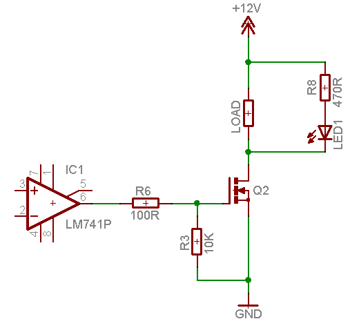
|
|
#
?
Mar 27, 2009 15:18
|
|
|
Sweevo posted:Going back a dozen pages or so: I've got an op-amp driving a MOSFET to switch a 5A load. Can I put an indicator LED in parallel with the load, or do I need to switch it separately? Nothing wrong with using the LED there, no.
|
|
#
?
Mar 27, 2009 15:55
|
|


|
Sweevo posted:Going back a dozen pages or so: I've got an op-amp driving a MOSFET to switch a 5A load. Can I put an indicator LED in parallel with the load, or do I need to switch it separately? Assuming thats a resistive load as indicated, no problemo. If that is an inductive load there may be the possibility of killing the diode with voltage spikes when turning it off.
|
|
#
?
Mar 27, 2009 18:00
|
|
|
An inductive load would probably kill the MOSFET too.
|
|
#
?
Mar 27, 2009 19:03
|
|

|
It's a resistive load - a heating element putting out about 60-70W. I may add a flyback diode to be on the safe side though.
|
|
#
?
Mar 27, 2009 19:16
|
|
|
Hey guys, I know this is a long show, but I'm desperate: I'm having trouble discovering the Sparkfun's WRL-08469 Bluetooth-UART bridge device. (http://www.sparkfun.com/commerce/product_info.php?products_id=8469, based on the NXP BGB203). When I am able to discover it, the link is good, and the device works as expected. Unfortunately, this only happens sporadically, and I am at a loss to figure out why. I've got the WRL-08461 interfacing with an Atmega 324P. The module is the only thing on our board running at 3.3 volts, so we're running the TX(from uC)/RX(to Module) through a voltage divider, which appears to be working fine. The supply is very clean (less than 3mV ripple). We have the TX and RX lines connected appropriately to the Bluetooth adapter, as well as power and ground. PIO5 goes to an LED through a 330 ohm resistor into 3.3V. Reset is pulled high, and run through a debounced push button. No other pins are connected. We're trying to discover the device using 3 different bluetooth adapters on 3 different computers. When we ARE able to discover the device, all bluetooth adapters are able to discover the device, so the problem is definitely device-side. When we run "AT+BTINQ" on the device, we are able to see all the devices in the area, and AT+BTSDP works as expected for these devices. Entering data mode using "AT+BTSRV=1" does not result in the device being discoverable. "AT+BTSRV=1,"Serial Port", 000000000000, 0" does not result in discoverabilit. Using AT+BTCLT to connect from the adapter to a PC doesn't work either. The only thing that appears to work is pressing reset over and over until the device is discovered. At that point, the link is solid and reliable, and behaves as expected. I'm at a complete loss. Any advice is appreciated.
|
|
#
?
Mar 28, 2009 02:55
|
|
|
the wizards beard posted:An inductive load would probably kill the MOSFET too. Good point.
|
|
#
?
Mar 28, 2009 04:05
|
|
|
Zuph posted:Hey guys, I know this is a long show, but I'm desperate: While I have never used this device, from reading the datasheet it sounds like it will enter the data mode whenever there is an active link. I would guess that it tries to set up a link on reset before it kicks over to command mode (hence why it works sometimes). At the risk of this being a dumb question, are you sure that you have proper communication? Can you read/write the device name? Assuming you have reliable communication with the module, my next guess would be some type of initialization or default value that need to be changed.
|
|
#
?
Mar 28, 2009 05:51
|
|
|
SnoPuppy posted:While I have never used this device, from reading the datasheet it sounds like it will enter the data mode whenever there is an active link. I would guess that it tries to set up a link on reset before it kicks over to command mode (hence why it works sometimes). The device enters data mode on reset, and the only thing that drags it back into command mode at that point is the escape sequence ("+++"). This works fine. Our wired communications with the device are rock-solid. The discovery problem persists even if we explicitly tell the device which server mode to enter (AT+BTSRV=1, "Serial Port", 000000000000, 0), which sets the device to become discoverable on RFCOMM port 1, advertising it's service as "Serial Port," and not give a drat about the host that attempts connection. We've been poring over ever single configuration option, restoring the settings to Sparkfun-default even. 4 days ago, wireless discovery and pairing worked flawlessly, and today, with the same hardware, same software and same settings, it doesn't.
|
|
#
?
Mar 28, 2009 14:13
|
|
|
I am currently building several robots which are attracted to light and have ultrasonic collision sensing. I'm now trying to think of a way to make the robots able to find and move toward each other in certain circumstances. I was going to use infrared emitters and detectors but the lights produce too much IR and overwhelm the LEDs. Any ideas for sensing systems to allow the robots to find each other? The system also needs to be as cheap as possible.
|
|
#
?
Mar 28, 2009 20:27
|
|
|
TwoShanks posted:I am currently building several robots which are attracted to light and have ultrasonic collision sensing. I'm now trying to think of a way to make the robots able to find and move toward each other in certain circumstances. I was going to use infrared emitters and detectors but the lights produce too much IR and overwhelm the LEDs. Put a few kHz or so square wave out the LEDs and a high-pass filter on the detector? e: high Mill Town fucked around with this message at 00:22 on Mar 29, 2009 |
|
#
?
Mar 29, 2009 00:16
|
|
|
Quick couple of questions here. First of all, I don't really know much about electronics but I can't stop myself from breaking stuff open. That said, I was recently playing a mighty fine game of CIV4 and my computer crashed horribly. Seeing as the screen went to poo poo and I knew the videocard's fan was busted, I figured it was overheating. I decided to remove the fan and play mcguyver by putting a casefan pointing towards it. Thats when I noticed 3 bloated caps. Some of them have already started oxidizing or whatever. So, any reasonable person would keep using the card for regular computer activities and wait to get a replacement card. But I don't have a car until tomorrow and I'm very bored. Obviously this meant rumaging through the boxes of crap in the house looking for some scrap that had matching caps. Well, the search paid off. I found the matching caps (I think) on an old motherboard. I used the soldering iron to remove them without too much trouble. And this is where you guys come in. - Is this advisable at all? - How do I test the caps? I have a multitester here but I don't really know how to use it. - Caps on the card: 6.3v 1000�f Skywell SHT (M) 105�C Rumaged caps: 6.3v 1000�f G-LUXCON 0067 (M) LZ 105�C Will they even work? Thanks for the input =)
|
|
#
?
Mar 29, 2009 00:21
|
|
|
CptAJ posted:Quick couple of questions here. First of all, I don't really know much about electronics but I can't stop myself from breaking stuff open. That said, I was recently playing a mighty fine game of CIV4 and my computer crashed horribly. Seeing as the screen went to poo poo and I knew the videocard's fan was busted, I figured it was overheating. I decided to remove the fan and play mcguyver by putting a casefan pointing towards it. Thats when I noticed 3 bloated caps. Some of them have already started oxidizing or whatever. Yes, this is advisable. Worst thing that happens is you screw up the card and have to buy a new one, which you were planning to do anyway. Those caps are compatible, so no problem there. The basic guideline when replacing caps is: same capacitance, same or higher working voltage. The only downside is that you can't really test them unless your multimeter has a capacitance test function. Does it?
|
|
#
?
Mar 29, 2009 00:25
|
|
|

|
| # ? May 21, 2024 13:07 |
|
|
Mill Town posted:Yes, this is advisable. Worst thing that happens is you screw up the card and have to buy a new one, which you were planning to do anyway. Those caps are compatible, so no problem there. The basic guideline when replacing caps is: same capacitance, same or higher working voltage. http://i39.tinypic.com/2livssx.jpg You tell me. Mine is almost exactly like that one.
|
|
#
?
Mar 29, 2009 00:30
|
|