


|
catbread.jpg posted:No, I'm saying if you have seperate data bits originally (serial input or similar), AND you want to do bit operations on them before the final output, save the conversion to the bitfield till the end. You're going to have to give an example, because I'm still not seeing where you're going with your original claim. Why is it more "optimized" to change elements of an unsigned char[] (or whatever data width you're receiving) before packing them into a bitfield, rather than packing the input into a bitfield and performing bitwise operations? catbread.jpg posted:That second algorithm is doing unnecessary operations if bitfield is initialised to zero. I wrote that off the top of my head, it was meant for clarity rather than operation count. e: If you're receiving code:csammis fucked around with this message at 22:31 on Apr 30, 2009 |
 #
?
Apr 30, 2009 22:21
#
?
Apr 30, 2009 22:21
|
|


|

|
| # ? May 8, 2024 22:15 |
|
|
csammis posted:You're going to have to give an example, because I'm still not seeing where you're going with your original claim. Why is it more "optimized" to change elements of an unsigned char[] (or whatever data width you're receiving) before packing them into a bitfield, rather than packing the input into a bitfield and performing bitwise operations? It's 6 of one, half a dozen of the other. Some cases will be fast if you don't pack, such as doing a conditional branch on the value of a bit (assuming your architecture has a branch-equal-to-zero instruction). If your bits are packed, you have to unpack before you can do the branch. Also, if you need to do bitwise operations within the field (like OR the first 3 bits together), it would be faster if they were already split out. In other cases, such as applying a bitmask, will have far more overhead. If you have 8 bits that are split into 8 registers, and you want to AND them with a constant, you need to do 8 AND operations.
|
|
#
?
Apr 30, 2009 22:39
|
|

|
Delta-Wye posted:it would appear the circuitry on the left turns it into a smart battery. If I were you, I would try and find a replacement li-ion cell, and just unsolder the smart battery circuitry (carefully) and resolder it on the new cell. I don't THINK that will hurt anything, at least - I think battery controllers keep cell health info, but it should gradually change to match the new cell, I would think. Worked like a charm. What I did was just remove the circuitry and solder it to the nokia battery's +/- and ignore the data pin. Then I soldered the circuitry back onto the ipod. Basically this:  I was gonna post some pics for your amusement at how ghetto fabulous it looks but I don't have my camera. Thanks for the help dude. You just helped me save a bunch of money. On another note, can someone link me to some good soldering tutorials/videos/etc? I need to polish my technique cause my craftmanship on this is pretty awful.
|
|
#
?
May 2, 2009 00:09
|
|
|
I have a question about static electricity and this seems to be a good place to ask it. I'm having issues with getting USB disconnects due to static electricity when using my DDR pads. The pads are huge metal things with polycarbonate/lexan/whatever panels that generate a ton of static as I stomp on them with my rubber-soled shoes. I don't have an issue with my Playstation 2, but it is probably built to withstand static better. I've learned that I can alleviate the problem temporarily by rubbing the panels with a dryer sheet, but that makes them too sticky. I also put a grounding strap on the pads themselves, which keeps them from shocking me when I touch them, but isn't enough to keep the USB ports on the computer from overloading. Here is a diagram of what I understand is going on. Black lines are grounded conductors, and blue lines are insulators which I assume are building up a static charge. What is not shown here are the wires that transmit the signals because I don't know what is going on there. What exactly causes USB ports to disconnect? Is it because of static on the shielding, on the insulation, or on the signal wires themselves? What can be done to control or contain the static?
|
|
#
?
May 2, 2009 17:10
|
|

|
You could consider using ESD protection diodes on the lines from the DDR pad to the control box. They're basically a component containing one of more standard or zener diodes. Any transients excess voltages will get shunted to ground. Digikey probablyhas a wide selection, but just make sure their turn-on/shunt voltage is significantly above the normal operating voltages of the circuit. Wikipedia has a bit to say about them: http://en.wikipedia.org/wiki/Transient_voltage_suppression_diode Be careful with putting them on the USB lines, though, as if they have too much capacitance they could cause a problem for Hi-Speed USB. You should able to find ones rated specifically for USB.
|
|
#
?
May 2, 2009 23:02
|
|


|
SecretFire posted:You could consider using ESD protection diodes on the lines from the DDR pad to the control box. They're basically a component containing one of more standard or zener diodes. Any transients excess voltages will get shunted to ground. Digikey probablyhas a wide selection, but just make sure their turn-on/shunt voltage is significantly above the normal operating voltages of the circuit. I've never heard of a TSV diode. Maybe that is what I need. I'm not worried about the connection speed, as I normally attach the pads through a cheap USB 1.1 hub, which seems to be less problematic than plugging straight into the computer for some reason. The hub nor the control boxes have anything that looks like TVS diodes inside, so maybe I'll get one of the USB-specific ones and put it inside the hub because that would be the easiest thing to do.
|
|
#
?
May 3, 2009 00:40
|
|
|
How come when I hooked this guy up to my PC's 5v rail, it flashed red and then died? http://www.frozencpu.com/ele-12.html
|
|
#
?
May 3, 2009 01:04
|
|


|
Otacon posted:How come when I hooked this guy up to my PC's 5v rail, it flashed red and then died? Did you replace an existing LED? If not, did you use a current-limiting resistor with it?
|
|
#
?
May 3, 2009 01:14
|
|

|
BattleMaster posted:Did you replace an existing LED? If not, did you use a current-limiting resistor with it? The LED I removed was a blue LED with no resistor (I checked under the heat shrink) which led me to believe it'd be a direct swap. I bought a 12v red one at Radioshack, and it wasn't bright at all, even after moving moving the molex pins to provide 12v. Then, I bought these - 3 of them - and moved the molex pins back to 5v. Each LED was blown. I need the following - a clear LED that displays a red color that is very bright and will work with either 5v or 12v. Can anyone help?
|
|
#
?
May 3, 2009 01:42
|
|
|
catbread.jpg posted:No, I'm saying if you have seperate data bits originally (serial input or similar), AND you want to do bit operations on them before the final output, save the conversion to the bitfield till the end.
|
|
#
?
May 3, 2009 01:56
|
|

|
So did you actually replace the LED or did you just hook up a few test LEDs directly to the power supply? I bet it actually does have a resistor because LEDs don't respond very well to huge amounts of current.
|
|
#
?
May 3, 2009 01:57
|
|
|
randyest posted:Why? Seems wasteful. what are you wasting?
|
|
#
?
May 3, 2009 02:57
|
|
|
Anything that involves getting or setting a bit value out of a byte is going to take more ops than doing boolean operations on bits represented with 0x01/0x00. Standard trade of time for space. It's a moot point unless you're scrambling for every cycle you can, and generally applies only if you've got serial data to begin with, or are going to do a LOT of bit manipulation to the same data. My Microchip samples arrived recently, 3x DSPIC33FJ128MC802, and 3x PIC32MX440F512H. Atmel is really scroogy with samples. However they do use an open source C compiler. Microchip wins this round, as I have access to an ICD2 and MPLAB with their C30 compiler. The DSPIC is a pretty nifty chip, you can assign your own pinout to any of the digital I/O peripherals, instead of being limited to a choice of a certain range. It's got a hardware MAC instruction, and runs at 40 MIPS. And it comes in SPDIP. And 3/6 + 1/2 PWM channels.
|
|
#
?
May 3, 2009 04:27
|
|
|
Ohh, PIC32. I've got me an MX440 from a failed project, I love the chip but I can't stand MPLAB. There's just something so elegant about MIPS...
|
|
#
?
May 3, 2009 07:01
|
|
|
This is a crapshoot, but has anyone messed with lvds signals on Xilinx FPGAs? I'm having trouble with mine...
|
|
#
?
May 3, 2009 07:02
|
|
|
Otacon posted:The LED I removed was a blue LED with no resistor (I checked under the heat shrink) which led me to believe it'd be a direct swap. I bought a 12v red one at Radioshack, and it wasn't bright at all, even after moving moving the molex pins to provide 12v. Then, I bought these - 3 of them - and moved the molex pins back to 5v. Each LED was blown. Your blue LED and your 12V Radio Shack LED had built-in resistors, which is why they did not burn out. Buy some more of those red LEDs, and put one in series with a resistor of 150 ohms or so on the 5V supply. Full details on wtf is going on are available at this link: http://www.kpsec.freeuk.com/components/led.htm
|
|
#
?
May 3, 2009 07:54
|
|


|
Can someone tell me how to splice together speaker wire? I have headphones and attempted to shorten the wire for them but I can't figure out how to reconnect the two wire ends after cutting out a section in-between. When I strip the insulation, I get what appear to the naked eye to be one copper wire and one green-insulated wire, but macro mode with my camera reveals they're both woven metal wires with something else inside... this whole thing connects to my ipod via a simple 2.5mm jack so it can't be complicated. But no matter what I do, I can't get any sound to come out of my headphones. Here's a close-up photo (my host). It's hard to see, the flash makes things bright, but basically there appears to be really tiny light-gray strands inside the woven copper and green wires. Don't know if the gray stuff is uncolored wire or if it's just fabric for strength. Also don't know how the copper and green wires stay insulated from each other, they appear to be right next to each other in the black insulation. 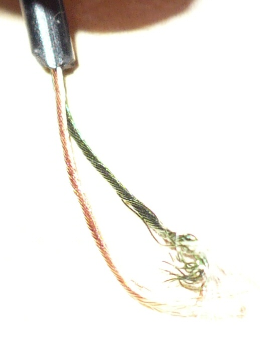 What do I do? EDIT: Nevermind. A google search with a different search term turned up this SA post on the same subject. Apparently they're ordinary wires with a plastic coating to prevent them for shorting against each other, and I guess I'll just have to go ahead and solder them together and then try it again. EDIT AGAIN: It worked! Yay. Heating the wires with a 40W soldering iron in an attempt to burn off the coating, then twisting them together, actually did not work, but when I then soldered that twisted connection, it suddenly worked. CGameProgrammer fucked around with this message at 10:12 on May 3, 2009 |
|
#
?
May 3, 2009 09:37
|
|
|
CGameProgrammer posted:Can someone tell me how to splice together speaker wire? I have headphones and attempted to shorten the wire for them but I can't figure out how to reconnect the two wire ends after cutting out a section in-between. When I strip the insulation, I get what appear to the naked eye to be one copper wire and one green-insulated wire, but macro mode with my camera reveals they're both woven metal wires with something else inside... this whole thing connects to my ipod via a simple 2.5mm jack so it can't be complicated. But no matter what I do, I can't get any sound to come out of my headphones. For future reference, fine-grit sandpaper can help you remove the epoxy that's coating the wires. You can also burn it off with a cigarette lighter. Edit: And that grey stuff is indeed fabric, for strength. Mill Town fucked around with this message at 10:41 on May 3, 2009 |
|
#
?
May 3, 2009 10:34
|
|
|
clredwolf posted:This is a crapshoot, but has anyone messed with lvds signals on Xilinx FPGAs? I'm having trouble with mine... Yes. What problems are you having?
|
|
#
?
May 3, 2009 15:37
|
|
|
SnoPuppy posted:Yes. What problems are you having? So I have an ADC with an LVDS output. I have three channels I'm using: bit clock, frame sync, and actual channel data. I got some sample ADC code for the device but it's not working very well. Even small changes seem to screw it up. I'm thinking I'm not meeting timing, even though Xilinx is telling me that I am. I'm not as familiar with timing in ISE as I am in Quartus, so I could be missing something. So how do I handle LVDS clock signals, especially high speed ones? (The bit clock is like 350MHz, hella fast) Right now, here are wires on the top module for the lvds signals: bitclock_p, bitclock_n framesync_p, framesync_n data_p, data_n I have bitclock_p marked as the clock. Bitclock_p and bitclock_n go to an lvds buffer, which feeds into a PLL. The PLL never locks (bad sign) and I get all sorts of transient errors. I don't think I'm handling LVDS clocks properly. I tried marking both bitclock_p and bitclock_n as clocks, and that didn't work any better! I'll show some sample code in a bit, I'm not at that computer. I do know that I have an lvds buffer set up like this: ibufds( .o(bitclock), .i(bitclock_p), .ib(bitclock_n) );
|
|
#
?
May 3, 2009 17:45
|
|
|
I would have assumed the synthesizer would figure this out automatically, but perhaps you could run the output of the ibufds through a global clock buffer (bufg)? I'm looking at some code I worked with recently that used an LVDS clock for RocketIO, and it looks like it does ibufds->bufg->pll_adv to generate the clock. Here's the code, for reference: http://code.google.com/p/infinibandfpga/source/browse/trunk/Physical/RocketIO_Wrapper.vhd. REFCLK_P and REFCLK_N are the differential clocks.
|
|
#
?
May 3, 2009 18:10
|
|
|
clredwolf posted:So I have an ADC with an LVDS output. I have three channels I'm using: bit clock, frame sync, and actual channel data. What FPGA are you using? And, the 64 thousand dollar question, are you using external termination resistors or have you turned on the internal LVDS termination (it's off by default)? Ok, I lied. There are a few other questions. Is the clock coming in on a global clock pin or a regional clock pin? Is your PLL configured correctly (i.e. appropriate multiply/divide settings)? Also, why are you using the PLL? Have you taken a scope to the clock input at the FPGA? Does it look clean?
|
|
#
?
May 3, 2009 18:35
|
|
|
SnoPuppy posted:Hmm...this wouldn't happen to be an 8 channel, 14 bit, 50 MSPS analog devices chip, would it? Yerp, that's the chip (I'm neglecting all but one channel for now). I'm using their evaluation board setup with a Virtex 4 VFX20. DIFFTERM = TRUE, so internal resistors (and their on). I think the clock is coming in on a global clock pin, but I'll have to check. The PLL was used in the original code. I tried to bypass it and it flat out stopped working. It's a DDR output from the chip (data on positive and negative edges) so I get the feeling there's some phase craziness going on. I stuck a spectrum analyzer on the clock input to the FPGA, and it looks like a great square wave. I think the hardware side of things is fine. Fifty-Nine posted:I would have assumed the synthesizer would figure this out automatically, but perhaps you could run the output of the ibufds through a global clock buffer (bufg)? I tried that as well, that's how it was set up originally. It worked like that, but changing the code around really messed with it. I'll take a look at that code though. I'm a Verilog guy though, reading VHDL gives me a bit of a headache 
clredwolf fucked around with this message at 20:54 on May 3, 2009 |
|
#
?
May 3, 2009 20:51
|
|
|
clredwolf posted:Yerp, that's the chip (I'm neglecting all but one channel for now). I'm using their evaluation board setup with a Virtex 4 VFX20. DIFFTERM = TRUE, so internal resistors (and their on). Wait...you're using a V4 with a PLL? Do you mean a DCM? Because V4's don't have any hardware PLLs. Two more dumb questions, but you didn't accidentally swap FCO and DCO did you? I know you said you have DIFFTERM=TRUE, but you are applying it to the correct IBUFDS instance, right? Have you checked with the FPGA editor? Or looked through the map report (that *.mrp file that ISE spits out) There shouldn't be any weird phase stuff going on with that chip, if I remember correctly. The fact that the DCM isn't locking (I assume you're monitor the lock bit in some way) would indicate either that: a) the input clock is bad. You should be able to tell this by driving it back out of the FPGA and checking with a scope or something. or b) The DCM is misconfigured. This is less likely, since they're pretty easy to deal with. Just look through the V4 users guide to check. or c) The ADC was not up and running when the FPGA bitstream was downloaded, or you didn't reset the DCM once its input clock was stable. You always have to reset the DCM if your input clock changes. Either way, you don't need a DCM to deal with this ADC. Just shift your input bits from the DDR flop into a register. Treat FCO as a data bit, since it has identical timing characteristics to the data bits. Then latch data out of your shift register when the FCO register matches "11111110000000". Then shove the data into a FIFO to cross the clock domain to whatever your "slow" clock is. Make sure you have all your proper OFFSET IN constraints for the DDR flops specified. I highly recommend making use of the debug modes on the chip while you're troubleshooting. They send out known data patterns and let you very easily catch off-by-one and timing errors.
|
|
#
?
May 3, 2009 23:33
|
|
|
SnoPuppy posted:Wait...you're using a V4 with a PLL? Do you mean a DCM? Because V4's don't have any hardware PLLs. Err yeah, DCM. My mistake. It has a DLL and I conceptualize it as a PLL. DCO and FCO are correct. DCO is not locking, I have the lock bit brought out to an LED. I haven't checked the MRP file, I'll do that next. I have the buffers set up like this though (I had to look back, it's not what I stated before, opps!): code:Thanks for the help SnoPuppy!
|
|
#
?
May 4, 2009 00:24
|
|
|
I was wondering if anyone here has some knowledge about serial communication. I'm writing some home automation software and I want to pick up temperature data from a 433.92 MHz temperature sensor. I'm using a RWS-434 radio receiver. It has a digital and analog output and using this I have been successful in sampling the signal with an oscilloscope. The signal does not contain any clock information and the transmitter sends the data about every 30 seconds. The bit rate is about 1800 bits per second and each transmission consists of the same data sent seven or six times, all in all a few hundred bits. I need to get this data into the computer somehow where I can decode it and read the temperature. I guess what I need is some way of sampling the output from the radio receiver at the same rate as the incoming bit rate and if a transmission is detected write this bit stream into memory for processing. For more info on how this stuff looks check out this guy's project page: http://bertrik.sikken.nl/433mhz/index.html Any suggestions on how to tackle this? I've been tinkering with electronics and computers for many years but never really done stuff like this. So I guess I'm kind of a n00b. Thanks!
|
|
#
?
May 4, 2009 14:27
|
|

|
clredwolf posted:Err yeah, DCM. My mistake. It has a DLL and I conceptualize it as a PLL. Those sounds like timing problems to me. I would guess that's due to using the FCO as an actual clock, without safely crossing that clock domain. Even though they're supposed to be related, if the tools can't tell then they won't take it into account. I suppose you could attempt to constrain it more (related clock period constraints), but that feels fragile to me. I believe you should be able to output a checkerboard patten from the ADC - that should make timing errors more evident. Also remember, ISE will generate a bitstream even if you fail timing, so make sure to check the log.
|
|
#
?
May 4, 2009 16:01
|
|
|
catbread.jpg posted:Anything that involves getting or setting a bit value out of a byte is going to take more ops than doing boolean operations on bits represented with 0x01/0x00. Standard trade of time for space. Interesting. What processors do you work with that don't perform a bitwise operation (shift left/right, rotate left/right, AND, OR, NOT, XOR) in a single opcode, or in more opcodes than an ADD or SUB arithmetic operation?
|
|
#
?
May 4, 2009 18:18
|
|
|
csammis posted:Interesting. What processors do you work with that don't perform a bitwise operation (shift left/right, rotate left/right, AND, OR, NOT, XOR) in a single opcode, or in more opcodes than an ADD or SUB arithmetic operation? I can kind of see the argument. With byte-representation bits you can branch immediately, whereas with bitmasks you have to load a constant beforehand, apply the bitmasking, then branch. There are quite a few optimizations I'd do before sacrificing a register for each bit in a bitmask, though.
|
|
#
?
May 4, 2009 20:15
|
|
|
I've got a decently interesting request from the guy I'm consulting for. He wants to make a low power logging anemometer that can measure the flow rate of air at various points in an industrial building. Anemometers are generally made using one of two methods. The first is to use something to convert the wind into electrical energy, like a small propeller or turbine or something. The other method is called the hot wire method, where you run some power through some temperature dependent heating element (like nichrome wire) exposed to the airflow, allowing you to measure the heat transfer, and thus the convection, and thus the flow rate. The hot wire method won't work because it requires too much power. He wants this thing to last at least 6 months on a couple batteries. Something like a propeller isn't really suited to low speed flow, since at low levels the friction and cogging associated with motors make them very nonlinear. My idea was to have the box mounted on a ceiling or something and it would have a sort of pendulum hanging from it. The pendulum would be able to swing freely (in one direction, for now) and would have a high drag coefficient. So any air flow would cause it to exhibit some steady state angular displacement. Modeling it accurately shouldn't be too hard. What I can't decide on is how to measure the angular displacement of the pendulum. I'm thinking that the pendulum would extend up into the device itself, so the sensing stuff could be enclosed. I can think of a lot of ways to do it: magnets and hall effect sensors, light reflection, light polarization... the thing is I need good sensitivity. The full range of the thing will probably be something like 5 degrees.
|
|
#
?
May 5, 2009 11:24
|
|


|
And about the C stuff, I wrote my bit banged asynchronous interface in assembly, then wrote it in C, and the C version took up seven times as much program memory and executed in a quarter of the speed. Probably a function of the difference in experience I have between the two languages, but I'm kind of disappointed in the WinAVR compiler. I even tried a premade CRC-16 algorithm and it still took up more resources than what I had written. I'm thinking I'll only really want it if I have to program something that uses fairly complex data structures like arrays and DSP and such.
|
|
#
?
May 5, 2009 11:35
|
|
|
ANIME AKBAR posted:And about the C stuff, I wrote my bit banged asynchronous interface in assembly, then wrote it in C, and the C version took up seven times as much program memory and executed in a quarter of the speed. Probably a function of the difference in experience I have between the two languages, but I'm kind of disappointed in the WinAVR compiler. I even tried a premade CRC-16 algorithm and it still took up more resources than what I had written. I'm thinking I'll only really want it if I have to program something that uses fairly complex data structures like arrays and DSP and such. Did the C version of your bit-banging code use any functions at all? In your earlier example that we helped you with you used a premade library function to write to I/O ports like outp(led, PORTB);. Does the compiler let you do something like PORTB = led; instead? PIC C18 lets you assign directly to hardware registers like that rather than wasting a lot of time calling functions to do it for you. I've gone over the disassembly of routines I've written and unless you do something really dumb the output it produces is often as good and sometimes even better than what you can write yourself in assembly. I'd be extremely surprised if something as well-developed and popular as the AVR toolset can't do that as well! BattleMaster fucked around with this message at 12:20 on May 5, 2009 |
|
#
?
May 5, 2009 12:15
|
|
|
ANIME AKBAR posted:I've got a decently interesting request from the guy I'm consulting for. He wants to make a low power logging anemometer that can measure the flow rate of air at various points in an industrial building. There's a guy balancing all the ducts in the HVAC system right now. The device he uses is a differential pressure system with temp and humidity sensor. There's a perforated tube that goes in the duct and another that's outside the duct. It calculates flow rate from air mass (based on humidity and temperature) and duct area. For places that don't have a duct (like the gym) the device sits in a collapsable nylon duct thing. This is the one he's got. (Click on "products").
|
|
#
?
May 5, 2009 12:21
|
|


|
BattleMaster posted:Did the C version of your bit-banging code use any functions at all? In your earlier example that we helped you with you used a premade library function to write to I/O ports like outp(led, PORTB);. Does the compiler let you do something like PORTB = led; instead?
|
|
#
?
May 5, 2009 13:05
|
|
|
ANIME AKBAR posted:I've got a decently interesting request from the guy I'm consulting for. He wants to make a low power logging anemometer that can measure the flow rate of air at various points in an industrial building. Anemometers are generally made using one of two methods. The first is to use something to convert the wind into electrical energy, like a small propeller or turbine or something. The other method is called the hot wire method, where you run some power through some temperature dependent heating element (like nichrome wire) exposed to the airflow, allowing you to measure the heat transfer, and thus the convection, and thus the flow rate. Accelerometer mounted on a deflecting beam? Analog Devices makes some pretty sensitive MEMS devices (0.025 deg of tilt per LSB).
|
|
#
?
May 5, 2009 15:11
|
|
|
How do you plan to send the airflow data back to whatever is logging/processing it? This sounds like a good application for a Zigbee device.
|
|
#
?
May 5, 2009 16:31
|
|

|
ANIME AKBAR posted:What I can't decide on is how to measure the angular displacement of the pendulum. I'm thinking that the pendulum would extend up into the device itself, so the sensing stuff could be enclosed. I can think of a lot of ways to do it: magnets and hall effect sensors, light reflection, light polarization... the thing is I need good sensitivity. The full range of the thing will probably be something like 5 degrees. Instead of a pendulum, how about a thin, flexible rod with a high drag coefficient sail/panel on the end. Then put a strain gauge or four (cheap as gently caress and very accurate when calibrated) on the flexible rod. Needs very little I/O circuitry besides a bridge and A/D and has a pretty simple analytical model to boot. Plexiwatt fucked around with this message at 17:11 on May 5, 2009 |
|
#
?
May 5, 2009 17:08
|
|
|
ANIME AKBAR posted:The io library comes with the compiler and all the examples I've seen use it. I'm pretty sure that outp function definition is the same as doing portB = led or whatever. I should have a look at the makecode it produces, but I hate having to look at the pure hex crap. The disassembler in avrstudio is pretty terrible from what I've seen. I went and had a look and it's actually a macro, so you're right. This page tells me that you can just skip using the macro altogether but it doesn't look like it would actually work differently either way. The only other thing I can think of is that perhaps optimizations are disabled when you do a debug build. Usually C compilers are better than humans at optimizing things unless the human does something really dumb.
|
|
#
?
May 5, 2009 17:35
|
|
|
Hillridge posted:How do you plan to send the airflow data back to whatever is logging/processing it? This sounds like a good application for a Zigbee device. Didn't someone mention homebrewing telemetry circuits? I've been meaning to ask about those for a while, since I have no knowledge of anything RF, and ZigBee is expensive.
|
|
#
?
May 5, 2009 22:17
|
|
|

|
| # ? May 8, 2024 22:15 |
|
|
Post the C.
|
|
#
?
May 5, 2009 22:30
|
|