


|
Delta-Wye posted:Should work. If it is serial controlled, RS232 should be fine over a 3 foot wire. If you are transmitting the direct signals for driving the LCD, they usually only run at 60-200Hz or something relatively low-frequency low-power and I suspect would be fine. I got my scales today (these guys) and promptly cracked one open to see if I could extend the LCD. It turns out that the LCD display is not even connected to the circuit board at all. There's a row of about 24 pins immediately below the LCD with what appears to be a black rectangular piece of plastic between the LCD and circuit board. The LCD also does not appear to have any connectors. It must send the signals to the LCD through inductance or something like that. I guess I can't extend the lcd
|
 #
?
May 20, 2009 19:31
#
?
May 20, 2009 19:31
|
|


|

|
| # ? May 21, 2024 10:38 |
|
|
dyne posted:I got my scales today (these guys) and promptly cracked one open to see if I could extend the LCD. It turns out that the LCD display is not even connected to the circuit board at all. There's a row of about 24 pins immediately below the LCD with what appears to be a black rectangular piece of plastic between the LCD and circuit board. The LCD also does not appear to have any connectors. It must send the signals to the LCD through inductance or something like that. Can you take a picture?
|
|
#
?
May 20, 2009 20:38
|
|

|
Sorry, I probably should've posted these before. They're awfully crappy cell phone pictures. Click here for the full 640x480 image. Just the circuit board  Click here for the full 640x480 image. With the 3 buttons and black rectangular plastic (which is directly over and comes in contact with the traces in the first picture)  Click here for the full 640x480 image. The LCD just sets on top of the rubber from the buttons and comes in contact with the black rectangular piece of plastic. I cannot see any sort of marking anywhere on the LCD that would indicate there being a connection. The LCD is normally held in place by the casing of the entire thing. Also note that I didn't snap anything off, I reassembled it and it works perfectly fine. edit: and if you're wondering why I want to extend the LCD: the scales will be mounted on a mill and I can't figure out a way to mount them so that the display is easily visible as-is. There's a few products that take the data signal (from the 4 traces in the upper right hand corner) and feeds it to an external display, but those cost a couple hundred bucks. dyne fucked around with this message at 22:05 on May 20, 2009 |
|
#
?
May 20, 2009 22:01
|
|
|
dyne posted:The LCD just sets on top of the rubber from the buttons and comes in contact with the black rectangular piece of plastic. I cannot see any sort of marking anywhere on the LCD that would indicate there being a connection. The LCD is normally held in place by the casing of the entire thing. Also note that I didn't snap anything off, I reassembled it and it works perfectly fine. I would guess this is the LCD connection here: 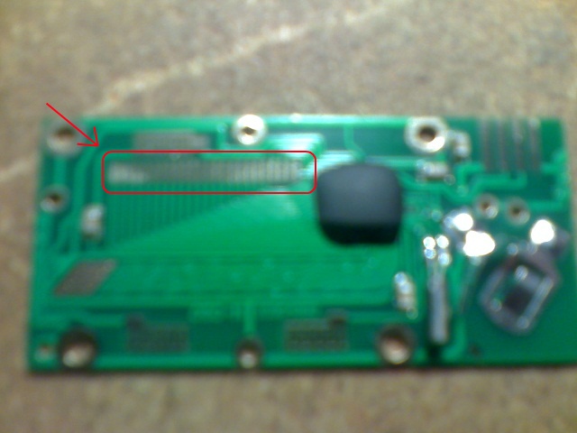 Click here for the full 640x480 image. As far as how the LCD connects to it, I have no idea. I would also guess that it is a HD44780 or similar under the black epoxy, but it's hard to tell. Can you get a non-blurry picture of the board and the back of the LCD? Sounds like a cool project, I would like to be able to help you but those pictures are pretty hard to make out.
|
|
#
?
May 21, 2009 01:09
|
|
|
Delta-Wye posted:I would guess this is the LCD connection here: I've seen those before, the rubber strip actually has conductive bits in it. Try taking an ohmmeter to it and you should find alternating bands of conducting and nonconducting material. It will be next to impossible to rig up an extension that makes a good connection, though. Rather than extending the wires to the LCD, why not extend the wires to the Edit x2: That page you linked also explains how the data signal works. With some effort, you could probably write a program for an Arduino or other �C that reads the data and outputs it to an LCD or LED display. Mill Town fucked around with this message at 06:37 on May 21, 2009 |
|
#
?
May 21, 2009 06:33
|
|


|
Mill Town posted:I've seen those before, the rubber strip actually has conductive bits in it. Try taking an ohmmeter to it and you should find alternating bands of conducting and nonconducting material. I'll crack the scale open again tomorrow to check about the rubber strip. The position sensor is the circuit board so I don't think that can be extended ") When I originally posted I was hoping that I would just be able to solder on a wire and extend the display, actually going through and making something that will read the data signal might not be something I'm able to do. I've only had an introductory programming class and assembled pre-designed circuits but not anything beyond that. I guess I could always use another project though, how much would an arduino and lcds run me? Would one board be able to process the data from 3 different scales? dyne fucked around with this message at 08:08 on May 21, 2009 |
|
#
?
May 21, 2009 07:53
|
|
|
It has taken me waaay too long to find an appropriate TTL input open collector quad AND gate... On a positive note, I got my PCBs back today! They came out really well for an etch job, only one broken track going to a tiny SSOP. Also got my current transducers (LEM LA 55-P), should do nicely.
|
|
#
?
May 21, 2009 09:55
|
|
|
dyne posted:I'll crack the scale open again tomorrow to check about the rubber strip. The position sensor is the circuit board so I don't think that can be extended Sparkfun will have both, and I bet you can get everything you need for ~$50 or so. I'm not familiar with Arduinos (keep thinking I ought to jump into it) but someone here can probably point you towards the right one. Is there any reason you can't solder on 40 or so wires? some light gauge + hot glue might be fine, assuming the lcd has similar sized pads. I wouldn't call that size soldering 'fun' but it would be doable.
|
|
#
?
May 22, 2009 03:48
|
|
|
clredwolf posted:Yay, I got a testbench working! If your TB is working on the RTL, could you try it with post-layout timing?
|
|
#
?
May 22, 2009 03:51
|
|

 Gives me all zeros.
|
Delta-Wye posted:Sparkfun will have both, and I bet you can get everything you need for ~$50 or so. I'm not familiar with Arduinos (keep thinking I ought to jump into it) but someone here can probably point you towards the right one. There's no reason I can't solder wires to the circuit board, it just doesn't look like there's anything to solder to on the LCD or the black rectangular piece of plastic (the 'zebra stripe'?). Do you think it'd be possible to use another LCD that I could actually solder the extension wires too? I kind of guessed that it wouldn't be.
|
|
#
?
May 22, 2009 04:00
|
|
|
dyne posted:Do you think it'd be possible to use another LCD that I could actually solder the extension wires too? I kind of guessed that it wouldn't be. Quite possible! I assume that its basically a bare LCD, so it will have a common pin (or two) plus pins for all the digit segments. It would probably drive most bare LCDs, but the trick is identifying which pins are which. I suspect it could be done with a logic analyzer and Are there identifying marks on the LCD? being able to find a datasheet would make it somewhat trivial.
|
|
#
?
May 22, 2009 06:05
|
|
|
I might be working on a research project soon, and one of the things that was mentioned was working to remove the lag in their measurements. I don't really know what specifics I can reveal, so I'll unfortunately leave things a bit vague. Also, I don't know many specifics anyway, so there really isn't much more I could say. I believe there is a microphone hooked up to a data acquisition card, which sends the data to MATLAB to be processed. MATLAB performs some computations and makes a decision based upon the waveform about whether or not to perform an action, such as playing a sound. This is what I believe is happening. The issue is that there is a 40-60 ms lag between the time of the sound and when MATLAB makes its decision to perform an action. Obviously it can't be reduced to no lag, but eliminating as much lag as possible would be very beneficial. I believe some of the lag might be associated with the data acquisition card. I've read that higher sampling rates lead to lower latency by the Nyquist limit. So there's a physical limit to how much lag can be reduced, and there's probably some lag introduced by the data acquisition card as well. The next part then is MATLAB. I'm not really sure what's involved in making the decision. It might just be the amplitude of the audio signal, or it might be more complicated. This is where I really wish I knew more about what they're doing. I've come to you guys to ask what you think of this problem. I'm not a complete novice, but this is quite a different problem from what I am usually faced by. Do you think replacing what they currently have with an FPGA might be appropriate for this, given what little information I've provided? If the logic is as simple as checking to see if the amplitude of the audio waveform is greater than some constant, it's probably complete overkill, but if it's more than that, should I pursue this thought further? Even before getting to that point, I'd probably propose upping the sampling frequency, if possible, and rewriting the MATLAB routines in C++, but I feel they might want something that seems more substantial than that.
|
|
#
?
May 25, 2009 02:19
|
|

|
ryanmfw posted:I might be working on a research project soon, and one of the things that was mentioned was working to remove the lag in their measurements. I don't really know what specifics I can reveal, so I'll unfortunately leave things a bit vague. Also, I don't know many specifics anyway, so there really isn't much more I could say. What are the latency requirements? Microseconds? Nanoseconds? Different ADCs will have different latencies, likewise with a DAC. If you need nanosecond I/O latency, you might be out of luck, depending on the ADC/DAC combo. Also, anything running in windows won't be real-time, because windows isn't a real-time OS (Not counting WindowsCE, which is soft real-time I think). Since you care about latency, I can only assume you're doing a control loop of some type. The Nyquist rate doesn't have anything to do with latency - it's only a relation between the minimum number of points to reconstruct a signal within the time domain. Generally if you're sampling faster you might get that first point faster, but not always. And if you need 10ms worth of data, you still have to wait that 10ms. To be honest, I wouldn't think that Matlab is the issue, unless they're doing some intensive computations. It's more likely that the latency is related to the bus transfer time between the capture card, the CPU, and the output card. How much data is being transferred? Lastly, don't optimize without knowing exactly where the problem lies, or else you run the risk of wasting a ton of time on something that may only be a minor improvement. See what your latency is if you don't do any processing at all, and use that as your benchmark.
|
|
#
?
May 25, 2009 09:37
|
|

|
ryanmfw posted:I might be working on a research project soon, and one of the things that was mentioned was working to remove the lag in their measurements. I don't really know what specifics I can reveal, so I'll unfortunately leave things a bit vague. Also, I don't know many specifics anyway, so there really isn't much more I could say. To give an example, say your system is looking for 100Hz on your input. It will do some digital filtering (perhaps a FFT), and look at the result. So say you suddenly introduce a 100Hz signal into the input. The program will not recognize it immediately. This is because in order to detect that 100Hz component, it has to take at least several samples over one or two periods of that 100Hz. So it will probably take 10ms for that 100Hz to be recognized by the program. This doesn't have anything whatsoever to do with your sampling circuitry or your computer's power; it's simply due to the nature of your signal processing. The more precise and accurate your signal analysis is, the more data it will take for the output to reach a steady state, and the more latency there will be. This will be true for pretty much any type of measurement (amplitude, RMS, frequency content, phase, etc). So your concern will be picking a signal analysis method that has a good balance between speed and accuracy. You haven't been very specific about what you want to do, so I can't really give any specific advice.
|
|
#
?
May 25, 2009 15:41
|
|


|
ryanmfw posted:Just to check - you do mean 40-60 _milliseconds_ right? That's pretty reasonable based on the system you're describing. I would bet that 90% or more of the latency lies within the operating system and driver. Most data aquisition cards are FPGA-based, so you can probably expect that the total latency of the signal input will look something like this: [Input] -> (latency of analog filters) -> (latency of ADC) -> (sample collection time) -> (latency of on-board FIR filters, if present) -> (latency of miscellaneous FPGA data pipelines) -> (latency of PCI interface) -> (latency of the operating system) -> (latency of the MATLAB driver) Now, most of these are pretty neglible. Unless you have monster lowpass analog filters your analog delay is maybe a couple of milliseconds tops. The latency of the ADC varies from device to device, but I've never seen an ADC with higher latency than 1ms (many are much lower). Then there is the sample collection time, which is the time required to transmit a sample from the ADC to whatever logic chips it feeds. The worst case delay for this is one sample's worth. Once the sample has made it into the DAQ card's processors (which are probably FPGA, CPLD, or ASIC), there is delay equal to whatever digital filters you have the card programmed to perform (if any). Then add the delay of a few pipeline stages just to be safe. If the card isn't doing any digital filtering then you're looking at _maybe_ 10 samples worth of delay at max. The latency of the PCI interface is negligible at audio frequencies. If you add all of those together (except for any custom digital filters within the DAQ) you would _maybe_ see 3-4ms of total delay. At most. (assuming you're sampling at some reasonable frequency.) Then you have the monsters, which are OS latency and MATLAB driver latency. I don't have any clue how you could eliminate those. There are some sound cards that come with very low-latency drivers (for use in DSP/MIDI applications), but I couldn't recommend on. Also the MATLAB driver hooks have much higher latency than you'd expect. Now, I would bet writing new MATLAB hooks or aquisition drivers is probably not high on your interest list. If processing latency is a big concern for your lab, consider moving the calculations out of MATLAB and into silicon (FPGA or otherwise). A lot of DAQ cards can be set up to perform on-board filtering. Alternatively, consider buying an FPGA evaluation board that comes with an ADC, a DAC, and a UART serial interface and then perform all the calculation on the FPGA.
|
|
#
?
May 27, 2009 08:33
|
|


|
Crossposted from a/v because this is not really audio related but about the electrical system/wiring. Simple question, just need someone to confirm. I had an audio problem that I was working on prior to putting my car up on jack stands for 2mo while getting new hub/bearing/tie rod end/brakes/etc, but nobody had been able to figure out what was wrong - PG sub amp kept on cutting out but would play fine at idle or w/o the engine on. Phoenix gold techs said it was automatically shutting off b/c it wasn't seeing enough voltage but had no idea why it wasn't getting enough voltage even with the cap. I've tried a bunch of different things but nothing really worked, then I had to stop to fix my car, and last night I thought of something - and diagrams are so necessary. Here's a rough sketch I stole from crutchfield and modified to reflect my audio system's current wiring:  I think the problem is the wiring of the cap - there's nowhere for the current from the cap to go to. So when my PG amp wants to use all 1600W it can't because my batt won't provide that and the cap is unable to due to the incorrect wiring, current can't flow backwards from the cap to the distro block. So my question is, can you confirm that I'm an idiot and that the below picture should be what my wires look like? Also, currently my PG sub amp (90A) is wired using 4ga whereas the cap is wired using 0ga. Should I 'downgrade' the +/- wires on the cap to 4ga? I don't think keeping the wires I have now and going from 0ga batt wire -> cap positive terminal -> 4ga wire to amp is a good idea, iirc bcae1 says that any time you go from a higher->lower gauge wire you need a fuse. I used 0ga for the cap cuz I had already bought some and figured bigger can't be worse and I had no idea what an appropriate gauge wire would be for a 2F cap. Along the same lines, can I keep the 0ga ground for the cap and switch only the + wire from 0ga to 4ga? Thanks guys. Possible future wiring setup that is 'good' aka it actually works: 
|
|
#
?
May 28, 2009 14:15
|
|
|
Soldering iron/station question: Which irons/stations do you folks use? I've started to get into joystick building which requires quite a bit of soldering to PCBs and I can't find any new tips for the econo-iron that I got. I was thinking of getting a WLC100 or WES51, but I wanna ask you guys that know more about this stuff before I make any more purchases 
|
|
#
?
May 28, 2009 14:49
|
|


|
scuz posted:Soldering iron/station question: I have a WLC100 at home, it works well and I like it. I've used WES51s before, and they work well and I like them too. Both are fine tools.
|
|
#
?
May 29, 2009 03:49
|
|
|
scuz posted:Soldering iron/station question: All depends on what you want to spend. I have a metcal that I paid about 100$ for and its pretty decent.
|
|
#
?
May 29, 2009 04:31
|
|
|
scuz posted:Soldering iron/station question: I have a metcal that's completely tits. It will solder large bulk metal structures, and with a 3-second tip swap will go straight into soldering very fine SMDs. I kinda wish I'd been able to get the two-tip model, since the second tip controller will work a solder sucker, but such is life.
|
|
#
?
May 29, 2009 08:58
|
|


|
babyeatingpsychopath posted:I have a metcal that's completely tits. It will solder large bulk metal structures, and with a 3-second tip swap will go straight into soldering very fine SMDs. Metcals are literally completely tits. Figuratively speaking, of course. Literally. Completely tits. I solder most of my personal projects at work after-hours because they've got a Metcal station and I'm too cheap to spring for my own. We have a dual-channel Metcal, the second channel of which usually has hot tweezers attached for removing SMD components.
|
|
#
?
May 29, 2009 09:33
|
|
|
Hi. I would like to build an integrated amp, maybe from a kit but working from a diagram that reads off what parts I need I might be okay. My building experience is a pair of speakers and little gimmicky electronics projects. Frankly I have no idea what I want because I don't really understand the options, which I am clearing up with a friend who builds all sorts of audio equipment. In my head I want to build something like a NAD int amp, just bare bones but great performance. Any ideas you can bounce off me or kits/diagrams/websites?
|
|
#
?
May 29, 2009 13:56
|
|

|
If I were doing this stuff full-time, I would consider a Metcal, but I'm just making joysticks using extracted controller PCBs. Probably should have specified this when I made my orginal post. $100 is all that I can really justify spending on this thing at the moment. However I really appreciate you guys pointing out Metcal because yes, they look utterly (udderly?) tits. How accurate is the temperature dial on the WES51? I don't need like 99.9% accuracy, just for it to be in the ballpark and not a placebo dial.
|
|
#
?
May 29, 2009 14:00
|
|
|
tokki g posted:Crossposted from a/v because this is not really audio related but about the electrical system/wiring. Your second diagram is the same as the first (save the fuse between cap and amp). I don't know why you think current cannot flow out of the capacitor, fuses don't care about curent direction.
|
|
#
?
May 30, 2009 05:47
|
|

|
turbo sex bat 4000 posted:Your second diagram is the same as the first (save the fuse between cap and amp). I don't know why you think current cannot flow out of the capacitor, fuses don't care about curent direction. I disagree. The first picture has one end of the cap going into the anonymous "power block", with no real indication of where it goes after that. The second picture, however, does appear more correct because the capacitor is connected across the power terminals of the amp (or at the very least, closer to the amp). That big capacitor is functioning as a decoupling cap, so it should be as close as possible to the device it's serving. This is especially true when dealing with very high currents, like you are. Ideally, you would have this cap almost on the power terminals of the amp, to minimize losses due to wire resistance and inductance.
|
|
#
?
May 30, 2009 13:51
|
|
|
turbo sex bat 4000 posted:Your second diagram is the same as the first (save the fuse between cap and amp). I don't know why you think current cannot flow out of the capacitor, fuses don't care about curent direction. Yeah I knew about the fuse stuff, but I thought that current wouldn't be able to flow both in/out of the 0ga wire going from the cap to the distro block in the first picture. I guess I'm wrong and current in circuits can flow in two directions...? Anyways, thanks, I'm gonna remove the cap entirely and see what happens; as well as try and find someone to rev the engine while I measure voltage and current under load. edit: SnoPuppy- you're both right I think. Both circuit diagrams will work, but the 2nd will work 'better' because there's no fuse between the 2F cap and the amp (whereas in the 1st picture the current from the cap can flow to either amp, possibly even the batt) and therefore there will be less delay for the current to reach the amp. However, I seriously doubt that those fuses will cause a significant delay. I haven't read any numbers, but if you can point me to some showing that ###A fuse causes ###sec delay that'd be great. tokki g fucked around with this message at 15:50 on May 30, 2009 |
|
#
?
May 30, 2009 14:13
|
|
|
tokki g posted:Yeah I knew about the fuse stuff, but I thought that current wouldn't be able to flow both in/out of the 0ga wire going from the cap to the distro block in the first picture. I guess I'm wrong and current in circuits can flow in two directions...? Fuses don't cause any delay. Nothing in this circuit causes delays. The reason you want to minimize the distance between components is as SnoPuppy said, to decrease losses in the cable. He is also right about placing the cap as close to the amp as possible.
|
|
#
?
May 30, 2009 19:47
|
|
|
I recently bought this soldering station off ebay. Hasn't arrived yet, but assuming it works as described, it'll be a sweet deal. Yeah, I know, off brand, engrish, etc. But similar capabilities with a brand like metcal or weller would cost five times as much. I also recently got a 54111D digital scope off ebay for 230$. Thing is a loving monster; easily weighs 75 pounds. But after calibrating it, it should be well worth its money. Next up I've got to get a good bench top power supply, a function generator, and a mess of spare components.... I'm slowly building up a personal workspace so I don't have to drive an hour to school to get some work done.
|
|
#
?
May 31, 2009 18:48
|
|
|
Hey guys, I don't know if any of you are following my electric tractor thread, but I've reached a stage where I need your expert advice. I have the choice of using 12v or 6v batteries, my motor runs on 48v, so I need eight 6v or four 12v. I want to use standard flooded lead-acid batteries to keep the cost under control, so I've found 2 examples. The 6v are rated for 150 amp hour, and the 12v are 104 amp hour. 8 x 150 = 1200 amp hours for 960 dollars. vs. 4 x 104 = 412 amp hours for 560 dollars. So naturally the 6volts are better deals from my perspective. The motor is rated at 4hp continuous, 6hp peak, so let's use 5hp for the calculations. 5hp ~ 3700 watts 48 volts means approx 77 amp draw for 3700 watts. 1200 AH / 77 = approx 15 hours of use at high throttle. Is my math sound? Have I overlooked anything important? E: I have missed something, catbread pointed it out in my project thread. 8 x 150 x 6 = 7200 Wh for 960 dollars 4 x 104 x 12 = 4992 Wh for 560 dollars. So that means 2 hours at full power with the 6volts? Slung Blade fucked around with this message at 00:37 on Jun 1, 2009 |
|
#
?
Jun 1, 2009 00:04
|
|


|
Just work off energy, it's easier. From your other thread: 8 x 150 x 6 = 7200 Wh for 960 dollars, compared to 4 x 104 x 12 = 4992 Wh for 560 dollars. Say at 3 kW draw, you're looking at 1.6 hours for the 12 V, or 2.4 for the 6 V bank.
|
|
#
?
Jun 1, 2009 00:18
|
|
|
Hmm, alright. That's a lot less time than I was hoping.
|
|
#
?
Jun 1, 2009 00:21
|
|
|
3 kW is a lot of continuous power.
|
|
#
?
Jun 1, 2009 00:24
|
|
|
Well, it will probably be ok. I don't have a lot of land and it won't be running flat out all the time. Are the other calculations sound?
|
|
#
?
Jun 1, 2009 00:37
|
|
|
I need pinouts for a whole bunch of electrical components. Is there some kind of website with a database of these? Google has failed me, and although Datasheets.org.uk seemed promising, it doesn't actually have any that I need.
|
|
#
?
Jun 1, 2009 00:50
|
|

|
Ensign Expendable posted:I need pinouts for a whole bunch of electrical components. Is there some kind of website with a database of these? Google has failed me, and although Datasheets.org.uk seemed promising, it doesn't actually have any that I need. Well what do you need? Be a little flexible with the designators when searching.
|
|
#
?
Jun 1, 2009 00:53
|
|
|
A few LED displays. AJ Toshiba-C TVC-2-HB, KLR4172 and one with no labels at all.
|
|
#
?
Jun 1, 2009 01:04
|
|
|
Delta-Wye posted:Quite possible! I assume that its basically a bare LCD, so it will have a common pin (or two) plus pins for all the digit segments. It would probably drive most bare LCDs, but the trick is identifying which pins are which. I suspect it could be done with a logic analyzer and Ah sorry I've been a bit busy and haven't thought about this much. There's no markings or anything on the LCD
|
|
#
?
Jun 1, 2009 02:31
|
|
|
My AV amplifier recently blew one of its channels. I found the burned trace but after repairing it the channel isn't working correctly. I have a schematic layout and a DMM. I know where the grounds are located but are amps usually AC or DC for volts/amps?
|
|
#
?
Jun 1, 2009 03:24
|
|
|
Slung Blade posted:Well, it will probably be ok. I don't have a lot of land and it won't be running flat out all the time. It's pretty sound, keep in mind your motors aren't going to be 100% efficient. Usually it's rated, so look at it, factor that in. If it's 80% efficient, it'll take 12 kilojoules over a second to make 10 kilowatts of output. Also batteries deteriorate over time, so you'll get less and less runtime. Keep in mind you can also bank batteries in parallel for even more runtime. With the 6V, you get 7.2 Wh/$, while with the 12V gives 8.9 Wh/$. So with two banks of 12V batteries, you get 9984Wh for $1120. It's more cost effective, but more costly too. Also, your batteries weigh a certain amount, so the more batteries the harder your motors have to work. So too much and your tractor won't move. I'm gonna guess you need a lot of umph to move a freaking tractor though, so it may not be a big deal. Just some things to think about.
|
|
#
?
Jun 2, 2009 01:31
|
|
|

|
| # ? May 21, 2024 10:38 |
|
|
ANIME AKBAR posted:I recently bought this soldering station off ebay. Hasn't arrived yet, but assuming it works as described, it'll be a sweet deal. Yeah, I know, off brand, engrish, etc. But similar capabilities with a brand like metcal or weller would cost five times as much. Good choice, I have that exact scope as well. The hot air pencil will really come in handy with SMD components. A good chunk of ancillary stuff, if you can get access to high precision measurement equipment, can be made. Amateur radio folks have tons of useful tools. Maybe start making a library of standards as well? Resistance, freq, etc. So when you don't have access to a decent lab you can still measure things well.
|
|
#
?
Jun 2, 2009 01:42
|
|