


|
Exitlights posted:About the wireless control code, though, I think that's where I'm headed next. I'm starting to look into pretty basic wireless transmitters/receivers, and this pair from SparkFun seems to be the ticket (very cheap): http://www.sparkfun.com/commerce/product_info.php?products_id=8950 and http://www.sparkfun.com/commerce/product_info.php?products_id=8946 . There are some pretty robust-looking tutorials to get these things talking, the range seems decent, the bitrate is fine for telling the car how to move its servos. I think I know how to wire up the receiver, but I'm a little torn about the transmitter. I would recommend Xbee, having played with a few of sparkfun's wireless offerings. I would get a pair of the Xbee units, a USB basestation, and a breakout board with sockets. The units use a non-standard spacing so the breakout board is necessary to stuff it into a breadboard/interface with it. I believe they also have an arduino shield, since that is your thing. A bit expensive as a package ($100!) but trust me, these have pretty cool characteristics. They do all sorts of error correction on the transmission, and can be flashed to act as serial repeaters - so no programming required at runtime. I have a pair set to transmit back and forth and it is as easy as connecting power, ground, tx and rx. When you're ready they can do all sorts of cool things beyond that, but until then you can just move them from project to project as they are socketed. A good starting arrangement is to program both in the basestation, and then breadboard one with the Rx and Tx pins shorted together, and try sending data with hyperterminal over the other. If your characters are echoed back, you are good to go. At that point you can just plug the rx and tx into your project - any microprocessor listening on the other end will get the data just fine until you are out of range. I'm a strong believer in the idea you get what you pay for, but who knows, you might be able to cobble the RF links together successfully.
|
 #
?
Sep 22, 2009 08:04
#
?
Sep 22, 2009 08:04
|
|


|

|
| # ? May 8, 2024 15:09 |
|
|
Hillridge posted:On a completely unrelated note, does anyone know where I can find details on the old NES hardware? I remember someone asking an NES question a while back. That was me. I'm slowly moving forward on the project, got the hardware prototype done, just working on software. There is a ton of information though it's scattered around on a number of websites and is of varying quality. http://nesdev.parodius.com/ http://www.zophar.net/documents/nes.html http://nesdev.parodius.com/bbs/index.php <-- Very active web forum http://www.raphnet.net/electronique/nes_mod/nes_mod_en.php That should get you started. I've saved a lot of the good docs to my computer so I wouldn't have to find them again whenever I needed the reference, is there something specific you're trying to find?
|
|
#
?
Sep 22, 2009 13:24
|
|

|
Basically I'm thinking about doing the same thing you are. Anyway, shoot me a PM if you want to toss some ideas around. Hillridge fucked around with this message at 15:23 on Sep 22, 2009 |
|
#
?
Sep 22, 2009 15:21
|
|

|
Looking for some details on a project I have in mind. I have limited electronics experience, I've built a altoids headphone amp from instructions so I know how to follow directions and solder enough to make it work ") I have a nephew who is 3 years old and loves to push any button or knob he can find. I was thinking of building a simple box that has numerous different switches and knobs and lights, etc. What I was thinking was something simple like maybe a breadboard with the bottom row having a control knob, a toggle switch, a push button with each controlling something above it. So a buzzer, a led, etc. basically things that will light up or make sound. Initial thoughts are a rectangle plastic box with holes drilled in the top and two rows containing everything. Top row being the noise and light and bottom being the switches and knobs. Probably battery powered with the box being kid proof to open. I'm not sure how and where to exactly get started so any help would be greatly appreciated.
|
|
#
?
Sep 22, 2009 20:43
|
|

|
What do you have in mind? Get some concrete plans, first. Draw out a top-down view of the project you want to build. Include all of the doodads. When you're done that, you can post it here, and we'll point you in the right direction. Oh, and here's a suggestion: if you put an offset weight on the shaft of a little DC motor, it'll move the project box around.
|
|
#
?
Sep 23, 2009 00:44
|
|

|
babby's first vibrator.
|
|
#
?
Sep 23, 2009 02:52
|
|
|
Any EE's want to give me some advice? I'm an electronic tech. by trade but have limited experience with PLC's. I know that doesn't make sense but we usually make our own controls because my VP hates them and would rather have us figure it out for the "fun" of learning. Also PC based things work better in our applications. Anyway I need to develop controls for a machine that will automatically fold a square cardboard box around a said product. My mechanical co-hort has a lot of the frame, pneumatics, and limit switches mounted. I picked an AB MicroLogix 1100 for my PLC because of the expandable I/O, about 15 valves and 10 switches. The machine is completely repetitive so I'd like to us some sort of sequencer instead of the normal way PLC's scan. There would just be one start button and out pops a box. There isn't any variables at all either. In RSLogix I see there is a function for it but have no idea how to use it. My question is really how would someone normally write this? Just using normal contacts and latches or should I read my AB instruction set manual more about this sequencer? Also is the sequencer function even act like a drum sequencer?
|
|
#
?
Sep 23, 2009 20:29
|
|


|
I just started going to college to become an EE. I keep hearing the good Electrical Engineers will have projects going on outside of school, are naturally curious about electronics and the applications thereof. However I don't have a whole lot of knowledge and/or experience with basic electronics. I was trying to think of some basic projects I could do to that would be interesting to me, somewhat useful, and hopefully grant me some basic experience. I'm not taking any major-related courses as of yet (Calc 2, Chem 1, Physics 1, a dumb required geology-related course). Here are some projects I figured would be a good start that I could find schematics for online and work through: Pocket Headphone Amplifier PC Fan Controller w/LCD for Temperature Monitoring FM Transmitter for MP3 Player Aside from that, do you guys have any recommendations on other projects would be good for me to get started with? Also, my dream job right now would be to work for a company like Intel, or NASA. Aside from getting good internships between my sophomore/junior and junior/senior years and having a good GPA, what other things should I be doing that would make me stand out for when I graduate? Any clubs I should look for/join? Aluminum Record fucked around with this message at 22:35 on Sep 24, 2009 |
|
#
?
Sep 24, 2009 22:32
|
|

|
Aluminum Record posted:Also, my dream job right now would be to work for a company like Intel, or NASA. Aside from getting good internships between my sophomore/junior and junior/senior years and having a good GPA, what other things should I be doing that would make me stand out for when I graduate? Any clubs I should look for/join? IEEE is the obvious one.
|
|
#
?
Sep 24, 2009 23:32
|
|
|
Hillridge posted:I fixed a problem I've been having with loading the config data into an FPGA via my ASIC. I watched the whole process on a logic analyzer and everything met the spec for the FPGA. What they didn't bother putting in the datasheet was that you have to toggle the clock line a few more times after the last bit has transferred for it to work. Xilinx FPGA? If so, they do actually document the start-up sequence, and allow you to switch to a different clock if you don't want to use the loader clock. At least on the Virtex 4/5 and Spartan3 they do.
|
|
#
?
Sep 25, 2009 18:19
|
|
|
I've been soldering down a lot of these fuckers lately. It's actually not that bad with a reasonable iron and really good tweezers. I'd try reflow, but there are lots of surface mount parts on both sides of the board, so that's not really an option.  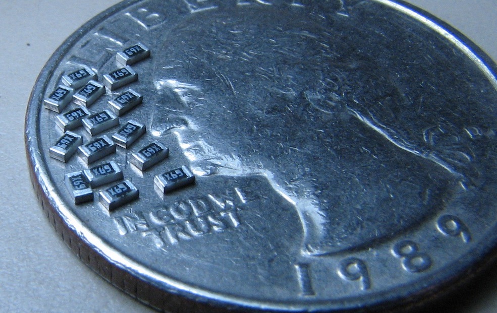
|
|
#
?
Sep 27, 2009 20:08
|
|
|
Do you have a really good magnifying glass and lamp or do you use a microscope? 
|
|
#
?
Sep 27, 2009 20:16
|
|


|
Please make a video of you doing this j4cbo!
|
|
#
?
Sep 27, 2009 20:38
|
|

|
603's? Those aren't too bad - no scope or other optics required. Now these suckers made me get out the scope:  Ignore the filename, they are caps, not beads. They are pictured next to a dime and came out of my ipod touch. SnoPuppy - It's actually an Altera. I think I have it working without the extra cycles now too.
|
|
#
?
Sep 28, 2009 15:34
|
|
|
I guess this is the place to post my question. I am having the darnedest time figuring out the solution to my problem. I have designed and built the following circuit: http://www.fetusporn.com/sa/circuit.gif Basically the momentary switch on the left toggles the JK flip-flop in the middle to trip/un-trip the DPDT relay which in turn runs the DC motor one direction or the other. This circuit works PERFECTLY provided that the motor (or any load for that matter) is not connected to the output of the relay. When there IS a load (motor) on the right side (output) of the relay, I get phantom flips (flops?) which prevent the motor from changing direction. When I press the button I do hear it flip for a fraction of a second (relay click, motor slow-down), but then it clicks back and keeps going in the direction it was already headed before the button press. With a non-noisey load like an LED strip, I still get the extra flip issue, so I've ruled out DC noise from the motor. However it only seems to do it when there is a large load on the output. Simply putting two opposite facing LEDS (with resistors) on the output works fine and I can press the button a hundred times to watch one turn on and the other turn off without failure. My thought now is that the relay is doing something which is freaking out my ICs. Any suggestions for further isolating my logic from the relay/motor/LED-strip? Thanks in advance. I'm about to rage quit and replace the whole shebang with a single DPDT relay and a latching switch to control it's polarity output. No logic, no problem (but not as cool )Edit: VVVV -- Yes, but notice that I said it also happens with just an LED strip on the output. Out of curiosity, where should I put the diodes anyway? FetusPorn fucked around with this message at 07:51 on Oct 1, 2009 |
|
#
?
Oct 1, 2009 07:01
|
|

|
You need some diodes. When your motor stops or switches direction, it becomes a generator which is backfeeding your network.
|
|
#
?
Oct 1, 2009 07:26
|
|


|
I'm taking apart my old broken 3G iPod (bored) and thought it might be fun to play around with the click wheel component. Any chance that someone knows the pinouts for it, or could help me discover them? I've checked pinouts.ru with no luck.
|
|
#
?
Oct 1, 2009 23:48
|
|

|
Aluminum Record posted:
The Cmoy is a good one. Try doing one with an active virtual ground too (ie put an opamp in it to hold the virtual ground at it's point, rather than using resistors and caps), it'll improve bass response and make it perform better. Something I've learned tinkering with mine. I can provide more details if you want. Also look into some kits. Things like robotic line followers are fun projects to start with. Also there are a ton of amplifier projects out there, from tube amps to high end solid state amps to low-part-count curiosities that actually perform very well indeed. Tube amps are fun to build, they use some pretty exotic topologies and it's interesting to see how it was done 'in the old days'. There's a good kit floating around that uses 11BM8 tubes and a nice feedback topology. Eventually you start to see little improvements here and there, especially when you do some coursework and start applying it. I've made 3 revisions to the Cmoy design, and I'm about to make a 4th with lessons learned from the 3rd. It's a fun process. Aluminum Record posted:Also, my dream job right now would be to work for a company like Intel, or NASA. Aside from getting good internships between my sophomore/junior and junior/senior years and having a good GPA, what other things should I be doing that would make me stand out for when I graduate? Any clubs I should look for/join? IEEE, Robotics Clubs (I'm a huge fan of them for practical learning), and if your university has it, co-ops (they're like internships but typically easier to get into).
|
|
#
?
Oct 2, 2009 03:43
|
|
|
If anyone experienced with building BEAM circuits could help me out with this, it would be much appreciated: With new and ridiculously tiny pager motors available now, I have embarked on a project to build really, really small photovore. I have some very small solar cells that I believe I can wire up in parallel as the power source, but I'm not sure if they're going to provide enough current for a Panasonic 1381-based circuit...they reliably put out 4V in bright light, but at only 1.6mA, and I have four of them. Assuming an ideal total of 6.4mA, is that going to be enough? It doesn't seem to me like those little motors are really going to require much current.
|
|
#
?
Oct 2, 2009 13:55
|
|

|
This place has some cool stuff for those of you who want to prototype, but can only find SMD parts: http://www.schmartboard.com/
|
|
#
?
Oct 2, 2009 18:05
|
|
|
First year Electrical Technician - Process Automation student here. First page really helpful as I'm looking to get a nice dc power supply unit, USB oscilloscope, and a frequency generator so I can complete my labs if need be. Plus I'm looking to get into some projects like amp building and what not on my own time. Again, great thread!
|
|
#
?
Oct 3, 2009 04:43
|
|
|
any of Yall use the mentor graphics "PADS" suite. I'm trying to make some part types and I'm having trouble with anything that's board layout isn't a pattern the wizard can make (QFNs DIPs or whatever.)
|
|
#
?
Oct 3, 2009 22:17
|
|

|
Powdered Toast Man posted:If anyone experienced with building BEAM circuits could help me out with this, it would be much appreciated: Well the cells won't be supplying the motor directly, so you'll just be waiting longer between bursts as the cap charges up.
|
|
#
?
Oct 4, 2009 20:45
|
|

|
Some friends of mine and I have gotten together an interesting assortment of equipment: 2 Stage Light transformers (massive, massive beasties) 1 Ignition Coil (2 if I ask nicely) 1 47uF capacitor (don't know the voltage, but it came with the stage light thing so I assume very high) We can probably get lots more of this stuff too. I was wondering what fun Would it be possible to have a cap at one end at high voltage, and 'pulse' it really fast to get lots of current but low voltage at the other end? This seems like it wouldn't work very well to me, but theoretically it should be fine... We can get some ridiculously high voltages though. These transformers are rated for a lot. I think we can almost hook a security alarm battery up to a beefy MOSFET and a 555 timer, and get some AC charge going. Maybe a big rear end marx generator? Hrmm...
|
|
#
?
Oct 4, 2009 23:57
|
|
|
You can use the transformers as one-shot pulse transformers to get lots of current out of a cap by charging it and hooking it up to the HV side. e: if you were really cool you could make a combined charging/rectification/pulse discharging system. catbread.jpg fucked around with this message at 05:17 on Oct 5, 2009 |
|
#
?
Oct 5, 2009 05:15
|
|
|
catbread.jpg posted:You can use the transformers as one-shot pulse transformers to get lots of current out of a cap by charging it and hooking it up to the HV side. Hrmmmmmm..... (in regards to the edit) This just gets more and more interesting. I like it. Idea you gave me looks like: battery -> DC/AC -> xfmr-> rectifier -> cap bank (HV) -> xfmr -> xfmr -> rail (LV) Now, how do I keep those discharge xfmrs from saturating. Wait, I know: battery -> DC/AC -> xfmr-> rectifier -> cap bank (HV) -> big rear end IGBT -> xfmr -> xfmr -> rail (LV) Arduino (PWM output) -> Optoisolator (and a good one at that) -> IGBT Gate 
|
|
#
?
Oct 5, 2009 05:25
|
|
|
I was thinking charge from the mains, assuming that the lighting transformers have a mains input? What are the specs of the transformers, I have no idea what a lighting transformer is and google doesn't help. If they are designed to be current-limiting (through the leakage inductance, then they probably won't be great as pulse transformers. You sooooo want an SCR. e: you plan to step down the voltage twice? e2: you want to PWM it? Why? I don't really see that happening. catbread.jpg fucked around with this message at 06:15 on Oct 5, 2009 |
|
#
?
Oct 5, 2009 06:04
|
|
|
I am trying to build a simple I2C controlled board for a stepper motor. Right now I have already gotten it working in a unipolar half stepping mode using a PIC18F2420 and a set of four BJTs. It works fairly well but speed and timing is an issue due to the 18F2420 working on timer interrupts (which limits my speed by whatever the interrupt frequency is). Since it is working in unipolar mode, I am getting half the power I could get if it was being run in bipolar mode. Additionally I want to generate a micro step to make the motor go faster and reduce vibration and I am fairly certain I don't want to take on designing a discrete circuit to do this if I do not have to. I have started looking into Allegro Stepper Motor driver ICs. What I plan on doing is hooking up a small uc such as an ATTiny25 or an 18F1320 to the I2C lines and then just doing a simple change over to interface with the Allegro IC. Anyone have any experience with Allegro's stepper controller offerings?
|
|
#
?
Oct 5, 2009 06:36
|
|
|
catbread.jpg posted:I was thinking charge from the mains, assuming that the lighting transformers have a mains input? Yeah, I was playing with it in a simulator, didn't quite work out the way I thought it would. I was thinking the transformer would discharge slowly, or wouldn't let the entire pulse carry through (like how a square wave will get this 'slant' to it if you pass it through a transformer). After some thought, that's wrong, the entire pulse from the cap will make it through because it's constantly changing as the cap discharges. It's by a function of euler too, which conveniently passes through unscathed. Opps. So yes, I want an SCR. Now I'm trying to figure out how best to use the transformers. I will look at them tomorrow, they're not at my apartment. I don't think they are current limiting. In any case, I still have the ignition coil, which may end up being the more exciting coil to use in any case. And I'm debating if I want to do mains charging or not. There's the safety factor, and the 'lets make this portable' factor too. In any case, an ignition coil (lets say I use this, not sure what the light xformers are) has turns of about 100:1. That corresponds to Rs*(100)^2 if I hook it up so that the HV side is the primary. So that means 10,000x the impedence is seen. So, I want the most current transfer possible. Do I go for power transfer anyways? My instinct says yes, my equation says more current^2 = more force. But the resistance of the iron while this thing is accelerating is going to change as it's moving, right? Just like in a motor. I guess I need to read up some more on the gauss gun's physics. I know capacitor ESR is going to play a huge role in this too, since the maximum power/current is going to depend on whether or not I can match that ESR value.
|
|
#
?
Oct 5, 2009 07:16
|
|
|
if it's for a gauss gun, then the leakage inductance of the transformer would play a significant part in the shaping of the current pulse. you might be better off connecting a capacitor directly, I dunno, see if anybody has ever used pulse transformers for such a thing. I guess you could do something like this. build it for comedy, test it o.c., and then stick a coil on the end of it to see what it does. 
|
|
#
?
Oct 5, 2009 11:24
|
|
|
Zaxxon posted:any of Yall use the mentor graphics "PADS" suite. I'm trying to make some part types and I'm having trouble with anything that's board layout isn't a pattern the wizard can make (QFNs DIPs or whatever.) I do. I'm more familiar with the schematic side of things, but I have a coworker who can probably answer your question.
|
|
#
?
Oct 5, 2009 12:57
|
|
|
So what are some good first Arduino projects some of you have done? I'm a professional developer, so the programming aspect of Arduino was picked up quickly, but I'm totally new to electronics. I've done some basic stuff, playing with flashing LEDs based on different controls and whatnot, interfaced with Python for a PC-side controller. I'm trying to find a good project to dive in though. Something that will really send me balls deep into the electronics aspect but keeping it sane, rather than simple little gizmos here and there that don't do anything. Some examples of stuff I had thought of was a scrolling LED marquee, or some cool way of controlling the lamp in my office (probably a bit over my head on that one).
|
|
#
?
Oct 6, 2009 03:49
|
|

|
Ferg posted:So what are some good first Arduino projects some of you have done? I'm a professional developer, so the programming aspect of Arduino was picked up quickly, but I'm totally new to electronics. Hey Ferg one thing that I just thought of that you could maybe do with the arduino (although it might be kinda clumsy physically) would be a POV flasher. Look into the miniPOV from adafruit to see an example... would be fun and a bit challenging on the code end. Also it keeps your circuit to mostly a couple leds with very little else. Now that I think about it... although this would be could it would be mostly software based but still something to think about.
|
|
#
?
Oct 6, 2009 13:16
|
|
|
Hm, I'll try to get a video of me putting down some small resistors. I've done all the 0603 for this project, but 0805 is similar enough in technique. The current build: 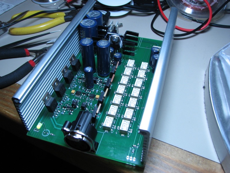
|
|
#
?
Oct 6, 2009 20:07
|
|
|
I am looking for recommendations for a nice handheld DMM but am not sure what brands to look at besides Fluke. I have used Flukes and a bunch of others at work but I am not sure if a Fluke 115 is worth the price over other similar DMMs. The Fluke 115 has pretty much the exact features I need would like to come closer to $75-100 USD as long as it doesn't sacrifice quality. I would also like a good set of test probes, IC hooks, etc, and would like a recommendation for a good set of those.
|
|
#
?
Oct 9, 2009 06:14
|
|

|
I wanted to update everyone on my newb electronics expedition: I've developed a serial data transfer scheme for controlling this old RC car I dug up, an on-screen controller, and hooked up all the servos and whatnot to my Arduino. After writing the code for the controller and Arduino, I tested it today and... complete success. I've got a wired RC (sans-R) car that I can now totally control with a little Processing applet I coded up. The next step is the wireless to put the R back in the RC, which I don't think is going to be too difficult (knocking on some serious wood right here). I've got a shipment of parts from Sparkfun coming so that I can communicate with my Arduino over a USB->RS232 adapter I bought... which is a pile of capacitors, a MAX232 chip, and a pinned-out DB9 female plug. Supposedly I'll be able to wire the output of the MAX232 chip to the transmitter, power it, wire the receiver up to the car, do some coding magic, and that might net me a working digital RC car.
|
|
#
?
Oct 12, 2009 06:51
|
|
|
Has anyone had any experience working with a parallax propeller chip? I bought a demo board and I'm slowly working through the code trying to understand it. Like any tips or projects you've done with them? Exitlights posted:I wanted to update everyone on my newb electronics expedition: I've developed a serial data transfer scheme for controlling this old RC car I dug up, an on-screen controller, and hooked up all the servos and whatnot to my Arduino. After writing the code for the controller and Arduino, I tested it today and... complete success. I've got a wired RC (sans-R) car that I can now totally control with a little Processing applet I coded up. Shazzner fucked around with this message at 18:05 on Oct 12, 2009 |
|
#
?
Oct 12, 2009 18:02
|
|

|
So, my current project is assembling the parts to build a complete synth/noise generator with an SN76477 I discovered in my parts bin (some of which were inherited from a music junkie, so it makes sense). There's a great circuit for this here (at the top of the page, the 1978 Popular Electronics article): http://mkv.itm.miun.se/personal/per/diy/76477/ (page 5 of the article) Looking at this circuit and the SN76477 in general, I sense that it should be possible to digitally control it to a certain extent. At a very simple level, it seems like it should be possible to simply replace the rotary switches for selecting resistor or capacitor inputs with transistors, but a 4016 or 4066 analog switch chip might be better. Some of the inputs are simple selections which are obviously easy to control. Others...it gets more complicated... (see also the datasheet, for the interested) Some of the inputs are control resistors, which are used in combination with the capacitor inputs. I don't completely understand how all of this is working, but it's easy enough to see that you've got a bunch of potentiometers that are being used to provide variable resistance values (tied to ground) for these inputs. I can of course envision something similar to the switched banks of capacitors with resistors instead, but this doesn't appeal to me. I don't even know where to begin to come up with a digitally controlled variable resistance value for these inputs. Is this even possible? I've seen servo-controlled pots in home theater equipment, but I would guess that they're quite expensive and given the vast number of digitally controlled synthesizers on the market, someone must have come up with a solution for this already... EDIT: Well sheeee-it, this looks promising: http://www.analog.com/en/digital-to-analog-converters/digital-potentiometers/products/index.html Powdered Toast Man fucked around with this message at 19:59 on Oct 12, 2009 |
|
#
?
Oct 12, 2009 18:31
|
|
|
Shazzner posted:That's cool, how did you figure out what frequency to use? Do you mind sharing your code? I'm also going to cross-post something I put on the Arduino forum, in case any of you know about the Arduino or USB->TTL ICs... quote:I did a search for anything like this, but I wasn't sure how to describe it concisely. I've got an Arduino Duemilanove that I'm trying to interface with serially (USB->RS232->TTL, which is the output). The circuit works great, and I'm able to communicate fine with my Arduino... Edit: I've narrowed the problem down further to just the battery causing the weird problem. Could it be a product of voltage instability in the battery? Is there some way to combat this? Exitlights fucked around with this message at 06:35 on Oct 13, 2009 |
|
#
?
Oct 13, 2009 04:36
|
|
|

|
| # ? May 8, 2024 15:09 |
|
|
Exitlights posted:I wanted to update everyone on my newb electronics expedition: I've developed a serial data transfer scheme for controlling this old RC car I dug up, an on-screen controller, and hooked up all the servos and whatnot to my Arduino. After writing the code for the controller and Arduino, I tested it today and... complete success. I've got a wired RC (sans-R) car that I can now totally control with a little Processing applet I coded up. catbread.jpg came out of the closet to say posted:[21:01] James: you should post in this thread for me
|
|
#
?
Oct 13, 2009 09:06
|
|
