|
So I finally got my RF transmitter/receiver in, and tried to convert my wired serial connection to a wireless connection. I used this 12v power supply that I also use for my external hard drive, and the transmitter got really hot. The whole system also refused to do any sort of wireless connection. No smoke or weird smell or anything, just lots of heat (especially in one transistor, I think it is). The part is rated between 2v and 12v, and my power supply does 12.15v by my multimeter's reckoning. When I plug it in now, it continues to get really hot, but still no smoke or smell or anything. How probable is it that I fried (or semi-fried) the piece and that's why it's not working? I'm going to do a bit more investigation when I get the chance, but I sincerely doubt it has to do with the receiver, or my wiring. But if that .15v over the rated max could have fried it... I'll go ahead and re-order the part now.
|
 #
?
Nov 8, 2009 01:34
#
?
Nov 8, 2009 01:34
|
|

|

|
| # ? May 22, 2024 09:46 |
|
|
Can you post a link to the part in question? To semi answer your question, most parts rated at 12v shouldn't mind 12.15. Need more info on it to be any more help than that.
|
|
#
?
Nov 8, 2009 01:45
|
|
|
Whoops, sorry, I meant to post that: http://www.sparkfun.com/commerce/product_info.php?products_id=8946
|
|
#
?
Nov 8, 2009 01:55
|
|
|
Thats a pretty straitforward transmitter circuit. I would really doubt that overvolting it by .15 is going to hurt it at all. It shouldn't be getting hot like that at idle either. You might try putting a lm7905 in front of it and see if it is happy with 5v. I would once over your circuit again but looking at the datasheet it's a no-brainer, I guess just make sure you don't have it backwards.
|
|
#
?
Nov 8, 2009 04:11
|
|
|
obso posted:Thats a pretty straitforward transmitter circuit. I would really doubt that overvolting it by .15 is going to hurt it at all. It shouldn't be getting hot like that at idle either. You might try putting a lm7905 in front of it and see if it is happy with 5v. I would once over your circuit again but looking at the datasheet it's a no-brainer, I guess just make sure you don't have it backwards. If I recall, it was only getting hot when I was pulling the data pin high (not 12v high, 5v). I put a lm7805 in front of it actually and it didn't get hot at all, but still wouldn't work. I'll poke around a bit more then, maybe I've done something wrong with it.
|
|
#
?
Nov 8, 2009 17:11
|
|
|
The comments on that Sparkfun device mention that it gets hot above 7V, so it may not be bad news yet.
|
|
#
?
Nov 8, 2009 22:11
|
|

|
What's the best way to get started on a USB joystick firmware for a PIC18F2455? I have a PICkit2. I've been pawing through the packaged code samples and pages online, but nothing has jumped out and seemed obviously superior. There are two methods I've yet to decide between... 1. Work from the Technical Brief 54 example talked about on here. 2. Work from the Microchip USB device HID Joystick example with a (free) third-party C compiler like SDCC. I haven't worked with PICs before, and I'm equally bad at 8051 assembly and C. BTW thanks to everyone involved in all the prior discussion on hardware setup, it was a great help.
|
|
#
?
Nov 10, 2009 10:23
|
|

|
Get the Microchip USB framework and use the included HID firmware as a base. Unless you're a crazy fucker like me who is willing to pour over the USB spec and PIC datasheet and write your own. The Microchip USB framework compiles with their own C18 compiler, so register on their site and get the free academic trial. It lasts forever, it only disables some of the better optimizations after 60 days which shouldn't be a big deal with what you're doing. BattleMaster fucked around with this message at 14:33 on Nov 10, 2009 |
|
#
?
Nov 10, 2009 14:29
|
|

|
Nice edit - I have been into the datasheet a fair bit and I just started reading the USB docs, but writing chapter nine from scratch isn't that appealing. And it's just a joystick right? Having it up and running is where the fun will be. I'll check out C18, thanks.
|
|
#
?
Nov 10, 2009 14:56
|
|
|
I feel like an idiot here, I've hit a brick wall modding this LCD screen. I'm trying to make the thing viewable in direct sunlight. Right now it works okay under overcast skies, but not at all in the sun. Currently the screen is lit by a string of LED's that run along the right side of the panel only. A desktop LCD would have a CFL light at the bottom AND top of the screen I believe. My plan is to either add a second string of lights along the left side of the LCD, OR to replace the current LED's with what I hope are much brighter ones. The benefit of replacing the LED's vs. adding new ones is that I can use the screen's buttons to control the brightness. My issue is that I bought an LED-light bulb that screws into a regular light socket, and has 15 or so LED lights inside, and plan on cutting these lights out to use. I have no way of measuring any sort of "forward voltage", or any of the other information I need to fill out this form: http://led.linear1.org/led.wiz I've got a 12v battery, good for 3.6 Amp-Hours that I'd like to power this thing with if I need to go with external power. Currently this 12v battery is powering the LCD itself. If I can power the LED's with the wiring that's in the screen already I think I'll have access to 5v of power from inside the monitor that is powering the current(very dim) LED array. Am I going to have to bite the bullet and buy some super bright LED's with documentation? I want really bright LED's, but not so bright they require the heatsink I've seen on some. Are there forums of Electrical Engineers out there I can PayPal $20 to design a simple circuit for me, or would something like that cost me hundreds? I just want these LED's I have no documentation for whatsoever to reliably burn as bright as possible, for extended periods. From this page: http://www.superbrightleds.com/cgi-bin/store/commerce.cgi?product=LEDS#RL5-W8045 RL5-W8045 White LED White Super Bright Led 8000 mcd / 45 Degree Viewing Angle OR RL5-W2545 White LED White Super Bright Led 2500 mcd / 45 Degree Viewing Angle $ 0.77 Both have a decent viewing angle, but since I'm shooting these lights into a diffuser in front of the LCD, would one of the 15 degree lights work better? I really don't need a wide spotlight. The 8000mcd would be the brighter light, yes? Any help would be appreciated, I've got a multimeter at home, with an analog display for measuring voltages if there are any little experiments I can do to figure out the voltages and resistance I need. I'm not concerned with burning out a few LED's in the process. bring back old gbs fucked around with this message at 17:53 on Nov 10, 2009 |
|
#
?
Nov 10, 2009 17:18
|
|

|
There are a few things to look at here. First of all, LED brightness is a factor of the current passing through them. If the LCD is limiting current to the LEDs, you may get some more brightness by lowering the resistance. The problem here, is that they probably limited current for a reason. Also, since you can dim it, the LCD probably PWMs the LED voltage. Replacing these LEDs with new ones is an option if the LCD can source enough current to power them. If you have a multimeter you can figure out the forward voltage of an LED pretty easily. At any rate, I doubt you will hurt super bright LEDs by powering them off of something designed for lower brightness parts. Do you have a model for the LCD screen?
|
|
#
?
Nov 10, 2009 19:42
|
|

|
If your multimeter has a diode setting, just stick the probes across the LED so that it lights up (dim is ok) and read the voltage. If it doesn't, put your LED in series with a large resistor (start with about 1.5k) and a 12V supply: 12V->LED->resistor->GND If it lights up, put the probes on either side of the LED and read the voltage. If it doesn't light up, decrease the resistance until it does. Hillridge fucked around with this message at 19:50 on Nov 10, 2009 |
|
#
?
Nov 10, 2009 19:47
|
|
|
Hillridge posted:
It's a Pyle PLVHR75 7" LCD UPDATE: Ran the wiring for the screen through the center post today.  Click here for the full 480x640 image. And here's a closeup of the battery portion I asked about a few pages back. All the help is really appreciated.:  Click here for the full 640x480 image. I still need to find a nice housing for it.
|
|
#
?
Nov 10, 2009 22:26
|
|
|
This says it has a Cold Cathode Filament Tube for a back light, not LEDs. You probably won't be making this any brighter, but you may still be able to add the extra LEDs. Any luck on finding the forward voltage?
|
|
#
?
Nov 14, 2009 04:38
|
|
|
Hillridge posted:This says it has a Cold Cathode Filament Tube for a back light, not LEDs. You probably won't be making this any brighter, but you may still be able to add the extra LEDs. Any luck on finding the forward voltage? That's a lie, I've had this screen torn apart. There are 12 small independent little bulbs mounted in a plastic housing to keep them in a line, not a tube. I'll snap a picture. EDIT: PICTURES  Cover off.  Wires going to the lights...  These are LED's, right?  Lit up  Meter on 50x setting, so 9v is making it to the LED's it seems. Oh yeah, and I saw these at an auto parts store the other day:  Click here for the full 477x646 image. These are replacement bulbs for cars, so it should work if I connect it to my 12v battery, right? bring back old gbs fucked around with this message at 22:37 on Nov 15, 2009 |
|
#
?
Nov 14, 2009 16:28
|
|
|
Is there an easy way to step up DC voltage? I'm trying to wire my headphone transmitter to USB instead of needing a wall wart because I am running out of outlets on my power strip at work (and this would obviously make it more portable.) Obviously I'd get 500mA @ 5VDC out of the USB (using one plug) but what I'm shooting for is 200mA @ 9VDC. This seems doable to me, since USB would be able to spit out 2.5W and the transmitter consumes 1.8W. Am I off base?
|
|
#
?
Nov 15, 2009 23:53
|
|

|
Ugg boots posted:Is there an easy way to step up DC voltage? I'm trying to wire my headphone transmitter to USB instead of needing a wall wart because I am running out of outlets on my power strip at work (and this would obviously make it more portable.) You can get a dc-dc/boost converter that will do that. Is the 9V/200mA rating from a wall wart for the transmitter? There's a chance that your transmitter is just regulating it down to 5V anyway. It might be worth opening it up and taking a look.
|
|
#
?
Nov 16, 2009 00:34
|
|
|
turbo sex bat 4000 posted:You can get a dc-dc/boost converter that will do that. Thanks. turbo sex bat 4000 posted:Is the 9V/200mA rating from a wall wart for the transmitter? There's a chance that your transmitter is just regulating it down to 5V anyway. It might be worth opening it up and taking a look. The 9V/200mA rating is on the transmitter, but I haven't opened it up to see if it's just regulating it down to 5V. Thanks for the idea to check.
|
|
#
?
Nov 16, 2009 01:17
|
|
|
Ugg boots posted:Thanks. Something like this, right? http://www.chipcatalog.com/National/LM2700.htm Edit: Or maybe a TL496? POKEMAN SAM fucked around with this message at 01:53 on Nov 16, 2009 |
|
#
?
Nov 16, 2009 01:49
|
|
|
Ugg boots posted:Something like this, right? http://www.chipcatalog.com/National/LM2700.htm That looks like it should do it. If you are comfortable making up a PCB, an IC like that is probably the way to go. Usually they require a number of other components (inductors, capacitors, trim pots). There are a bunch of cheap pre-built dc converters that will give you 5V out, but 9V doesn't seem to be very common.
|
|
#
?
Nov 16, 2009 04:03
|
|
|
I want to build a peak hold module. This is the setup: I have an input from a sensor, and it is sent to an electronic gauge that comes with the sensor. It's an analog signal AFAIK (3 wires...hopefully it's analog?). Most of the time the gauge just needs to show what it gets from the sensor. However I am going to store the peak value and when a switch is flipped, the gauge needs to show the peak value instead. I guess there are two ways to implement this: 1) Passively monitor the sensor data, and when the switch is flipped, bypass the sensor signal and output my own signal to the gauge. This way the gauge is normally reading directly from the sensor. 2) Instead of passively monitoring the signal, I actually take the signal and do my own output based on the signal. In other words, I play "man in the middle" and the output is always coming from me, and I am either replicating the sensor data or replacing it with my own value. Which approach would be better? I prefer #1 because I am only mucking with the signal when I want to show the peak value, however I have no idea how to build the circuit to "flip" the signal. I kind of have a better idea of how to do #2, I think. Maybe use a BJT to output my own signal? Anyway, help! Or tell me where I can go for some help or how I can get started.
|
|
#
?
Nov 16, 2009 17:45
|
|

|
ozziegt posted:I want to build a peak hold module. This is the setup: What's your setup for transmitting the peak value, if you've gotten that far? I don't see any reason you'd go with #2. The sensor is always transmitting data, and your device is always sending the peak value, the switch would just toggle which one connects to the gauge.
|
|
#
?
Nov 16, 2009 21:41
|
|

|
ante posted:What's your setup for transmitting the peak value, if you've gotten that far? As far as transmitting the peak value, I don't really know how to do that. I know I need to output an analog signal on the microcontroller but beyond that I am in a fog...can I just output directly to the gauge or do I need to do something like output to a BJT which would then send the signal to the gauge? I see what you are saying about the switch, my controller will never even listen to the switch's value...that sounds a lot simpler.
|
|
#
?
Nov 16, 2009 21:54
|
|
|
What microcontroller are you using? You'll need some sort of DAC, and many microcontrollers come with them. If yours doesn't, no biggy. External DACs are usually better anyway. Either way, you'll need one. You'll also need to figure out how the sensor works. It will either generate current or, more likely, have a variable resistance. Play around with it using a multimeter if you have one. It should act just like a potentiometer. One of the leads should be the pole, and the resistance between the other two leads will always be constant.
|
|
#
?
Nov 16, 2009 22:09
|
|
|
I'll be using either an ATMega or ATTiny. Either way, I'll have a DAC. So if it has variable resistance, how do I simulate that with the microcontroller? e: nvm, I think I understand...I just need to output the same voltage that the sensor would output when given the proper input voltage. Right? My understanding is that the gauge is controller with a stepper motor. Does that change anything? ozziegt fucked around with this message at 22:21 on Nov 16, 2009 |
|
#
?
Nov 16, 2009 22:14
|
|
|
ozziegt posted:e: nvm, I think I understand...I just need to output the same voltage that the sensor would output when given the proper input voltage. Right? ozziegt posted:My understanding is that the gauge is controller with a stepper motor. Does that change anything? Possibly. It's probably fine if it has controller circuitry, but double-check that the microcontroller isn't going to be directly driving the motor. That'll burn it pretty fast.
|
|
#
?
Nov 16, 2009 22:30
|
|
|
ante posted:Possibly. It's probably fine if it has controller circuitry, but double-check that the microcontroller isn't going to be directly driving the motor. That'll burn it pretty fast. What I've been told is that the sensor sends the signal to the gauge and the gauge has the controller built in. I'll confirm when I have the gauge myself, but that is what it seems like so far. Thanks for the help!
|
|
#
?
Nov 16, 2009 22:32
|
|
|
I have a new project: I'm going to design a machine which can fill a case of beer bottles with homebrew. I figure I can scrounge parts from a printer or scanner to move the hose/nozzle assembly from bottle to bottle, and I'm going to use a solenoid and a pinch valve to shut off flow from the input bucket, but I'm having trouble figuring out how to stay on target with the bottles themselves. Measuring from the cases of bottles I have laying around, they're just imprecise enough that without some sort of intelligent bottle targeting, I'm just going to get beer everywhere. I'd like to avoid the mechanical complexity of a Z-axis moving the booze-extruder up and down (if I could do this, a simple mechanical funnel would do), but I can't think of any remote way of doing this that doesn't sound ridiculous. A small, cheap CMOS camera would be able to take a picture of the bottle, and a simple edge-detection algorithm would probably get me close enough to the center of the opening. Some intelligently placed IR sensors might accomplish the task, but if they're level with the beer bottles, I'm not sure how to guarantee that I don't bang the assembly into bottles. I need help brainstorming this one out.
|
|
#
?
Nov 16, 2009 23:50
|
|
|
Could you make four intersecting bars close in on the neck of the bottle, locking it in place? That should probably centre it well enough to drop a funnel into it. edit: or some sort of lasso, you could drive that with a single stepper ante fucked around with this message at 00:36 on Nov 17, 2009 |
|
#
?
Nov 17, 2009 00:33
|
|
|
ante posted:Could you make four intersecting bars close in on the neck of the bottle, locking it in place? That should probably centre it well enough to drop a funnel into it. I could, but I'd rather avoid the added complexity of something dropping town into the bottle. I don't have the skill or tools to create anything mechanically complex, but I am moderately confident enough in my ability to create something more complex logically.
|
|
#
?
Nov 17, 2009 05:23
|
|
|
Is the lack of precision due to the bottles themselves, or the case holding them? If the latter, just make a filling rig that locks them in uniform positions, or make it work more like a factory where the bottles are fed in one by one and you have to manually place them in the case afterward.
|
|
#
?
Nov 17, 2009 13:42
|
|
|
Hillridge posted:Is the lack of precision due to the bottles themselves, or the case holding them? If the latter, just make a filling rig that locks them in uniform positions, or make it work more like a factory where the bottles are fed in one by one and you have to manually place them in the case afterward. Due to the case itself. I like the idea of a filling rig. I'd like to avoid the factory line feeling, since the point is to, at the very least, fully automate the most tedious part.
|
|
#
?
Nov 17, 2009 14:36
|
|
|
you could just make a grid (wire, wood, plastic, whatever) that you pop over the top of the bottles to snug them up evenly to each other. That way all you have to do is put on the grid, the machine fills the bottles, you remove the grid and close the case. I still think the most tedious part of filling bottles is sanitizing them first. Especially if they were used as ashtrays 
|
|
#
?
Nov 17, 2009 14:48
|
|
|
You do realize that you'll have a foamy mess if you don't have SOME sort of z-axis travel to insert a tube or filling wand, right? Just pouring the beer from a spigot will oxidize it and make a mess, especially if it's already force-carbonated.
|
|
#
?
Nov 17, 2009 17:34
|
|
|
jailbait#3 posted:You do realize that you'll have a foamy mess if you don't have SOME sort of z-axis travel to insert a tube or filling wand, right? Just pouring the beer from a spigot will oxidize it and make a mess, especially if it's already force-carbonated. Definitely won't be filling the bottles with already carbed beer. Foam is going to be a concern, but I hope to be able to modulate flow rate so this isn't a problem. Also, after years of homebrewing, I'm not at all convinced that casual oxidation has any tremendous effect on a batch, of all the things that can't be controlled for in a homebrew situation, and even less convinced that the small drop into a 12 oz bottle is going to have any effect at all, let alone something readily detectable. I'm receptive to objective evidence to the contrary, but I've never read or experienced anything convincing. I really like the removable frame idea.
|
|
#
?
Nov 17, 2009 17:45
|
|
|
Well, last weekend I learned how to use solder paste to do surface mount soldering and reflow with a toaster oven. I have to say that I couldn't believe how easy it was if you just use the right materials and tools. As my first project I put together a breadboard power supply module that runs off USB (it also provides a serial port). Money shot from the reflow here: http://www.youtube.com/watch?v=_5lksMvmqQc One pretty slick tool that was provided by the teacher was a laser cut mask, laid on top of the board and exposing only the solder pads. This allowed application of the solder paste with the edge of a piece of plexi, and just the right amount got on the pads. It is, however, quite possible to use a syringe for each spot if you're a masochist. 
|
|
#
?
Nov 17, 2009 20:12
|
|

|
I have a 14.8V lithium battery power source that I want to connect to low amperage 12V fluorescent lights (the ones people used to put inside computer cases) Linear regulator or buck converter? If buck, any tips/links on building a very simple one for my needs? Edit: I found this handy calculator for building a buck/boost regulator using TIs chip http://www.nomad.ee/micros/mc34063a/index.shtml but it would be so much more handy if I knew what it all meant  I'm not sure what the voltage ripple or frequency minimum are and I can't really tell what pins on the IC are actually the regulated voltage output I'm not sure what the voltage ripple or frequency minimum are and I can't really tell what pins on the IC are actually the regulated voltage output
dwoloz fucked around with this message at 08:09 on Nov 18, 2009 |
|
#
?
Nov 18, 2009 07:56
|
|

|
The easiest way to do it is to look for a complete DC-DC module from a place like digi-key. It'll have a little pcb in it that has a switching regulator and all the associated parts on it and only brings out 3 pins - Vin, GND, Vout. These can be a bit pricey though. What is the voltage on the battery near the end of it's safe discharge range? If it is less than 12V you may want a buck-boost topology instead. As for your questions, Vripple is your maximum acceptable voltage ripple on the output. Since that is a switching regulator it will produce pulses which are smoothed by the inductor (L) and cap (C0) to create a DC-like voltage. Vripple is the amount of the pulses that don't get smoothed, and for some applications it is critical to keep this as low as possible. A Vripple of 100mV means that your 12V output will be a 100mV (peak to peak) AC voltage on top of a 12V DC offset. Switching frequency can also affect parts of a circuit, so that other box is for setting your target minimum. Typically, a faster switcher means a smaller L and C is needed to smooth the output. Vout isn't just a pin per se, as the output of this chip needs to go through inductor L before it can be used. You can see Vout in the lower right of that picture, where the inductor and Cap meet.
|
|
#
?
Nov 18, 2009 12:20
|
|
|
Powdered Toast Man posted:One pretty slick tool that was provided by the teacher was a laser cut mask, laid on top of the board and exposing only the solder pads. This allowed application of the solder paste with the edge of a piece of plexi, and just the right amount got on the pads. It is, however, quite possible to use a syringe for each spot if you're a masochist. You can also usually just lay a thin line down across all the pads. the solder will leave the appropriate gaps when it flows. Occasionally you have to wick a little extra out between the pins but it looked like you were going to have to do that to the second chip in the video anyways.
|
|
#
?
Nov 18, 2009 18:56
|
|
|

|
| # ? May 22, 2024 09:46 |
|
|
Quick question for somebody just getting into building circuits. I'm trying to make a 555 circuit to flash a pair of LEDs, but I can't even get the LEDs to light up. I'd like to know if I built it correctly. Also, any breadboard layout tips? I'm working off this schematic: 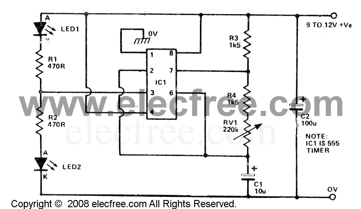 Click here for the full 1199x696 image. My breadboard looks like this:  Click here for the full 1600x1200 image. greg_graffin fucked around with this message at 07:18 on Nov 19, 2009 |
|
#
?
Nov 19, 2009 07:10
|
|