


|
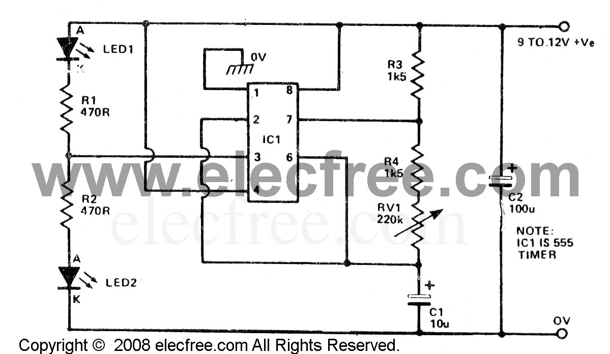
greg_graffin posted:Quick question for somebody just getting into building circuits. I'm trying to make a 555 circuit to flash a pair of LEDs, but I can't even get the LEDs to light up. I'd like to know if I built it correctly. Also, any breadboard layout tips? 1. Looks like pin 4 should be going to Vcc, not ground. 2. What's going on with the LED on the far left? Looks like it's getting shorted to ground. 3. Your resistor values are all different than the schematic. That might be intentional if you're playing around with different frequencies. 4. You are... Powering the circuit, right?
|
 #
?
Nov 19, 2009 07:35
#
?
Nov 19, 2009 07:35
|
|


|

|
| # ? May 21, 2024 13:45 |
|
|
Edit: Oh god I resized the image but not the background. Can a mod please delete this? Sorry I missed your message last night. Your resistors are close enough. A few things though: 1. Check your breadboard to make sure the + and - buses run the whole length. Some boards stop in the middle and need to be jumpered. 2. The cap i circled in blue can just be stuck on one side of the power buses, no need to span the board. 3. Change the green wire from - to + like ante mentioned 4. I think you are shorting the + to the - in the back there where I drew the ?, but I can't see for sure. It looks like the yellow wire goes to the first row, which is jumpered to the first row on the bottom by that red wire, then to ground by the green wire. Hillridge fucked around with this message at 15:55 on Nov 19, 2009 |
|
#
?
Nov 19, 2009 15:50
|
|

|
Zuph posted:Definitely won't be filling the bottles with already carbed beer. Foam is going to be a concern, but I hope to be able to modulate flow rate so this isn't a problem. Also, after years of homebrewing, I'm not at all convinced that casual oxidation has any tremendous effect on a batch, of all the things that can't be controlled for in a homebrew situation, and even less convinced that the small drop into a 12 oz bottle is going to have any effect at all, let alone something readily detectable. I'm receptive to objective evidence to the contrary, but I've never read or experienced anything convincing. A simple sensing setup could be done with two diffuse stick sensors like these: http://www.automationdirect.com/adc...SS-z-FA_Series) Looking down on your filling rig, place one sensor north of the nozzle and one east of it. For your purposes the speed that the nozzle moves, it's acceleration and its stopping time are all constant (any case of bottles it going to be really close in dimension to any other). Start moving north, when the sensor picks up the leading lip of a bottle, either stop immediately or start a timer and stop after X ms. You could adjust where the nozzle stops in relation to the center of the bottle by adjusting the timer and the distance from the nozzle that the north sensor is at. Start moving north again. Depending on where that north sensor is positioned, you will either have to ignore the first reading when you start to move or ignore the second reading as you're stopping (that's the trailing lip of the same bottle). Count how many bottles you're filling. When you reach the end of a row, move east one column using the same technique and then retract the nozzle all the way back to the beginning row. Start the north filling sequence over again. Repeat until everything is full. You could make it faster by adding a third sensor south of the nozzle, then you could fill in the south direction rather then having to retract after each row. If you go with diffuse sensors, make sure that you get a sample to experiment with first. I've used them on a range of surfaces before but never colored glass. Keebler fucked around with this message at 19:35 on Nov 19, 2009 |
|
#
?
Nov 19, 2009 19:32
|
|

|
^^^^^^^ Thanks I'll try all those out. Hopefully this will get easier for me over time ")
|
|
#
?
Nov 19, 2009 19:33
|
|

|
greg_graffin posted:Hopefully this will get easier for me over time Yeah it will. 555's are a lot of fun and will teach you a lot about analog circuits.
|
|
#
?
Nov 20, 2009 03:19
|
|
|
greg_graffin posted:^^^^^^^ Also I can't tell from here, make sure your LEDs are the right way, they are polarized. Anyway, I am looking for a basic cell jammer schematic, any idea where I can find one?
|
|
#
?
Nov 20, 2009 09:26
|
|
|
Dassiell posted:Also I can't tell from here, make sure your LEDs are the right way, they are polarized. Anyway, I am looking for a basic cell jammer schematic, any idea where I can find one? Bottom's definitely in right, but that's true, can't tell for the top. Cell jammers are illegal in most places 
|
|
#
?
Nov 21, 2009 00:31
|
|
|
Anyone know where to find a crapload of enamel wire cheap? Time to make a big sparky thing. (Friend of mine and I decided to work on a Mini-SSTC, and then turn it into a computer-controlled sparky thing.)
|
|
#
?
Nov 23, 2009 04:38
|
|
|
ante posted:Bottom's definitely in right, but that's true, can't tell for the top. Thanks man!
|
|
#
?
Nov 24, 2009 08:17
|
|
|
Can anyone tell me what this component is? It's labeled "FL2" on a laptop motherboard. (Dell D510)
|
|
#
?
Nov 25, 2009 16:42
|
|
|
PainBreak posted:Can anyone tell me what this component is? Probably a filter of some kind. No way to know its value though with the instrumentation to measure it.
|
|
#
?
Nov 25, 2009 17:51
|
|
|
My guess is EMI filter, gets rid of power line noise. Could be wrong though... No idea which pin is which...if I'm right there should be two pairs of 'shorted' pins if you test them with a meter (as in, 2 pins are negative side, two pins are positive side).
|
|
#
?
Nov 26, 2009 00:30
|
|
|
I would guess that it's a common mode ferrite bead, which would indeed be for EMI purposes.
|
|
#
?
Nov 26, 2009 08:07
|
|

|
I'm playing around with a class-E amplifier and need a good switching FET to use. I don't know much about the common FETs; I need something that can handle about 1W - 2W and has good switch-like characteristics (ie, high impedance when off, very low impedance when on). The lower the required gate drive the better. clredwolf posted:Anyone know where to find a crapload of enamel wire cheap? Time to make a big sparky thing. Check ebay. Always tons of magnet wire.
|
|
#
?
Nov 29, 2009 22:16
|
|

|
Frequency? Forward current? Blocking voltage? Low Rds-on and a low gate capacitance (and thus gate charging requirement) are usually mutually exclusive.
|
|
#
?
Nov 30, 2009 05:34
|
|
|
64 MHz, Low Rds.
|
|
#
?
Dec 2, 2009 00:54
|
|
|
catbread.jpg posted:Forward current? Blocking voltage?
|
|
#
?
Dec 2, 2009 08:45
|
|
|
I suppose those are what I'd want to pick from. Lower forward current is better. Blocking voltage maybe 10 volts.
|
|
#
?
Dec 2, 2009 14:57
|
|
|
I mean load current. I suppose it going to be hard-switched? N-channel? Wait, 64 MHz!?
|
|
#
?
Dec 2, 2009 19:41
|
|
|
64 MHz! I know they exist... Hard-switched, N-channel, load current say, ~200 mA.
|
|
#
?
Dec 3, 2009 05:26
|
|
|
You should definitely read this. http://focus.ti.com/lit/ml/slup169/slup169.pdf And then you should tell me why you want to switch at 64 MHz! A 15.6 ns period is certainly interesting. http://www.ixysrf.com/products/switch_mode.html http://www.ixysrf.com/pdf/switch_mode/de150_101n09a.pdf This will probably do what you want, if somewhat over-specced, good luck with the drive circuitry! It's 'rated' for 100 MHz operation, but note the combined rise and fall times (with perfect drive circuitry) are 8 ns. Fortunately your load current is low enough, as the switching losses will probably be in the order of 1W (10V * 200ma * 1/2)
|
|
#
?
Dec 3, 2009 08:27
|
|
|
I'm interested in building a high voltage, low current power supply so I can make my own ozone generator like this guy did with a cold cathode driver: http://www.bigclive.com/oz.htm I've already made one with a cold cathode driver from a dead flatbed scanner, but what's the fun in using something pre assembled? I'd like to put one of these power supplies together on my own so I can tinker with it. I built the 555-based inverter described on this page http://joshua.raleigh.nc.us/LM555-inverter/ and while it does a nice job lighting up electroluminescent wire, I don't get the nifty corona discharge and ozone like the scavenged cold cathode driver produces. I assume this is because it does not produce as high a voltage as the cold cathode driver. Is there any way I can modify this circuit to output higher voltage, like by modifying the frequency at which it runs, or is the winding ratio of my transformer the limiting factor? I noticed on the cold cathode driver, the transformer has 5 taps on the input side (feedback windings?). I've always been rather bewildered by transformers with multiple windings and taps.
|
|
#
?
Dec 7, 2009 06:58
|
|
|
Cyril Sneer posted:64 MHz! I know they exist... For the FET, you'll want the smallest possible geometry that can handle the current and voltage (what is the voltage?). A simple 2n7000 could probably suffice, at least to test with. For gate drive, that TI document catbread posted has a lot of good stuff, but it's meant mostly for applications where you are switching half or full bridges and you want to avoid shoot through current and whatever, but that doesn't matter for a class E amp. ANIME AKBAR fucked around with this message at 17:14 on Dec 8, 2009 |
|
#
?
Dec 8, 2009 17:10
|
|


|
I'm working on building a tiny lightweight gps tracker that charges and interfaces over usb. To power it I want to use lipo batteries. I expected there to be quite a few single chip/supporting simple component solutions out there for 3.3v devices because of digital cameras/pdas, etc, but all I seem to find are qfn, llp, etc package solutions. Do any of you know of a chip that would fit the bill for a 3.3v system? I'm looking for: -Is not qfn, llp, etc packaged (It is possible to solder without a hot air gun or hot plate) -Charges a single cell via USB, preferrably higher than 100mA -has a built in 3.3v ldo regulator for components that at an absolute, but unlikely MAX use say...200mA. -indicates charge states (charging/done charging is good enough) -protects battery from over/under voltage + is smart enough to limit itself if the charging IC gets too hot. -has low battery indicator -if possible power the device in an uninterrupted manner when switching from battery/usb power. I see quite a few solutions for charging.. and quite a few solutions for power management, but I must not be looking for the correct terms since I can't seem to find a chip that does both. macpod fucked around with this message at 05:16 on Dec 10, 2009 |
|
#
?
Dec 10, 2009 01:54
|
|
|
nobody- posted:I'm interested in building a high voltage, low current power supply so I can make my own ozone generator like this guy did with a cold cathode driver: Frequency won't change the output voltage. The transformer and the input voltage are the limiters. Either get a different transformer or raise the DC voltage powering the 555. In both cases, make sure that you check the 555's datasheet. It has limits in both what kind of current it can drive, and what input voltage it can take. There are many different kinds of 555s with many different specs. macpod posted:I'm working on building a tiny lightweight gps tracker that charges and interfaces over usb. To power it I want to use lipo batteries. You're looking for a one-chip solution?
|
|
#
?
Dec 10, 2009 05:33
|
|
|
Yes if such a thing exists, am I crazy? If not I really just need a setup that will: -Safely charge 1 cell lipo battery via usb and provide charge state like the max1555 does.. but hopefully a little better than 100mA -Regulate battery power, let me know when the power is low, and kill everything so I don't drop the battery voltage too low and make stuff explode. Sorry if I posted too many random specs.. data sheets do that to me.
|
|
#
?
Dec 10, 2009 05:43
|
|
|
macpod posted:Yes if such a thing exists, am I crazy? I highly doubt such a thing exists. In the next few years we'll likely see some microcontrollers with built in GPS (or more like GPS with a built in microcontroller). Your battery charging spec is a lot more dubious... battery charging ICs are application specific, so it wouldn't really make sense to integrate it into something general purpose like a gps or mcu IC. But charging and regulation ICs are pretty small and cheap, so it shouldn't take up much additional space or cost. Most battery management ICs will have some I/Os that indicate whether the battery is dying or whatever, and can automatically shut off when necessary. I'd recommend linear technology parts.
|
|
#
?
Dec 10, 2009 09:37
|
|
|
nobody- posted:I'm interested in building a high voltage, low current power supply so I can make my own ozone generator like this guy did with a cold cathode driver: also the driving circuit on that website is... bad. using the transformer in a flyback topology probably gets high output voltage, but it's doing terrible things to the drive transistor. driving it with a full or half bridge would be much better. ANIME AKBAR fucked around with this message at 10:42 on Dec 10, 2009 |
|
#
?
Dec 10, 2009 09:42
|
|
|
Nice to see you back anime ackbar, what's up?
|
|
#
?
Dec 10, 2009 10:18
|
|
|
around the time I was incidentally banned in LF I found out there was a bunch of poo poo that was threatening to prevent me from graduating this semester. seemed like a good enough excuse to stay off the computer for a while and focus on school. now that's all wrapped up and I should be going to grad school in the spring. tried to find a job, guess how that turned out... welp, at least I can boast about being told by an interviewer that I'm "too capable to hire."
|
|
#
?
Dec 10, 2009 10:49
|
|
|
ANIME AKBAR posted:I highly doubt such a thing exists. In the next few years we'll likely see some microcontrollers with built in GPS (or more like GPS with a built in microcontroller). Your battery charging spec is a lot more dubious... battery charging ICs are application specific, so it wouldn't really make sense to integrate it into something general purpose like a gps or mcu IC. But charging and regulation ICs are pretty small and cheap, so it shouldn't take up much additional space or cost. Thanks for the reply but I must not have explained what I am looking for well enough. I am aware a gps, microcontroller AND battery management units combined do not exist.. that's too specific. What I am looking for is a single chip solution for charging batteries and power management. Yes, Linear, maxim, and national semiconductors all make single chip solutions for this as I have pointed out in my initial post, but the problem is they are all qfn, llp or other difficult to solder packages. I am simply looking for a chip like this easier to solder. Edit: Something like a max8819.. but in a sop package or so. macpod fucked around with this message at 15:00 on Dec 10, 2009 |
|
#
?
Dec 10, 2009 14:55
|
|
|
macpod posted:Thanks for the reply but I must not have explained what I am looking for well enough. TI has a huge selection of chips that do exactly what you're looking for TI Power Management Some of their chips are available in TSSOP packages, and they are usually pretty good about samples to play with. However, in my experience they are too much work to be worth getting running. I think you would be better off with a max1555 and a battery protection circuit. If you are interested, I can post schematics to a LV/HV cutoff circuit I reverse-engineered for an electric vehicle team at school. ANIME AKBAR posted:tried to find a job, guess how that turned out... welp, at least I can boast about being told by an interviewer that I'm "too capable to hire." 
|
|
#
?
Dec 10, 2009 18:32
|
|

|
well I didn't look terribly hard; most of the places I was really keen at working for (keithley, stanford research, linear tech, analog devices) weren't hiring full time at all. I'd probably need a master's degree to get a spot with one of them anyways.
|
|
#
?
Dec 10, 2009 19:36
|
|
|
macpod posted:Edit: Something like a max8819.. but in a sop package or so. here's a part that seems to fit your application precisely: http://www.linear.com/pc/downloadDocument.do?navId=H0,C1,C1003,C1037,C1078,C1088,P23412,D15637 it comes in an MSOP package with a central body pad. not terrible difficult to solder, especially if you have hot air. but MSOP is somewhat fine pitch (0.5mm) so it will take some skill. do you have a hot air gun? if so, then you might be surprised how easy it is to solder a small DFN package (which is what many charging ICs come in).
|
|
#
?
Dec 11, 2009 13:05
|
|
|
That is a great find, thanks a bunch! I had looked through Linear's product tables before but missed it. I'm not too familiar with chip packages as you probably noticed and the MS-10 escaped me. And yea, the max8819 was a bad example. I was just trying to show something to reiterate I was looking for a "single chip power solution" not a receiver/power/controller combo. While I don't have a hot air gun I don't foresee too many problems soldering this. I have soldered MSOP chips before with a 1/32" soldering tip without much trouble. To get to the bottom pad I can alway make a large via I suppose. I also recently picked up a 100-500C (used  ) laboratory hot plate which could be useful for this. That's actually another project for the winter. ) laboratory hot plate which could be useful for this. That's actually another project for the winter. I'm going to grab a k-type thermocouple, AD595AQ (or something similar, since these chips are expensive), and either a (triac, optocoupler, fuse) or (ssr, fuse) combo to drive this 600W 120v hot plate. To act as a PID controller I was thinking of using an arduino and this library: http://www.arduino.cc/playground/Code/PIDLibrary I'm on the fence about the triac vs ssr at the moment. Control vs safety... hmm. Given other folks have made similar setups with ssr I guess the switching frequency isn't too much of an issue. The internals of the device as-is are pretty bare.. just a heater, no temperature monitor (sadly) so I can't scrounge up those components. Thanks for the help again! macpod fucked around with this message at 19:57 on Dec 12, 2009 |
|
#
?
Dec 12, 2009 19:55
|
|
|
I have a circuit design that uses PWM to dim a number of LEDs. It's run off of 24VDC and the LEDs are connected to switching MOSFETs which switch the anode side of the LEDs to ground at a very high rate (somewhere around 20KHz). The LEDs are arranged in series circuits of 7 with a power resistor. I just had someone tell me that the power resistor always needs to be between the cathodes and the +24V line, otherwise "any voltage spikes will not be dampened by a linear impedance". What the hell is he talking about here? Does it really matter which side of the LEDs I put my power resistor on?
|
|
#
?
Dec 12, 2009 21:27
|
|


|
No
|
|
#
?
Dec 12, 2009 22:17
|
|
|
hahaha no
|
|
#
?
Dec 13, 2009 07:28
|
|
|
Also why are you switching LEDs at 20 kHz?
|
|
#
?
Dec 13, 2009 10:31
|
|
|

|
| # ? May 21, 2024 13:45 |
|
|
No, but make sure you don't have your resistor backwards, or it could fail unexpectedly.
|
|
#
?
Dec 13, 2009 14:37
|
|