


|
Avenging Dentist posted:One of the first Google results is for a DirectDraw overlay, which is probably functionally similar to Direct2D: http://www.gamedev.net/community/forums/topic.asp?topic_id=359319 Well unfortunately it seems like with Windows Vista/7 the directdraw overlay does not work with 3d applications. Guess it's back to searching! I have discovered the only way to do this is to detour the direct3d functions a program calls? Sweeper fucked around with this message at 20:55 on Jan 16, 2010 |
 #
?
Jan 15, 2010 07:07
#
?
Jan 15, 2010 07:07
|
|


|

|
| # ? Jun 3, 2024 22:18 |
|
|
Hubis posted:not without doing some pixel shader tricks, no.
|
|
#
?
Jan 20, 2010 14:42
|
|

|
This is a bit of a ridiculous question because it seems so basic, but: I can't get smooth scrolling in OpenGL (using ortho projection). It seems to be because the floating point coords are getting rounded down (which makes sense) and I wouldn't have thought it would be noticeable at 60 fps, but it is. When I use integer coords, everything is fine.
|
|
#
?
Jan 20, 2010 20:51
|
|

|
ultra-inquisitor posted:This is a bit of a ridiculous question because it seems so basic, but: I can't get smooth scrolling in OpenGL (using ortho projection). It seems to be because the floating point coords are getting rounded down (which makes sense) and I wouldn't have thought it would be noticeable at 60 fps, but it is. When I use integer coords, everything is fine. From my limited perspective on General Programming, properly declared float values aren't going to round themselves down unless you're turning them into ints OR you're running math with both ints and floats as values, which could either truncate your floats or add a .0 to your ints depending on some poo poo. Try tracing your values and making sure that you're only operating on floats with floats and ints with ints, sorry if this didn't help very much.
|
|
#
?
Jan 21, 2010 03:29
|
|

|
Alcool Tue posted:From my limited perspective on General Programming, properly declared float values aren't going to round themselves down unless you're turning them into ints OR you're running math with both ints and floats as values, which could either truncate your floats or add a .0 to your ints depending on some poo poo.
|
|
#
?
Jan 21, 2010 15:23
|
|
|
I've never worked with GLSL before but I spent some time reading about it tonight and it sounds pretty interesting. I'm working on a little 2D game that currently uses a bunch of textured quads and renders them using VBOs. The quads are never rotated and never change size, but the texture coordinates change fairly often for animated sprites and that kind of thing. Is it possible to store texture coordinates and the height/width of the quad in the normal or something that I don't use, and instead render everything as a bunch of point sprites? I'm thinking I can set up the texture coordinates and quad size in a vertex/fragment shader.. Am I way off base? Am I likely to see much increase in throughput by doing so?
|
|
#
?
Jan 25, 2010 02:17
|
|

|
not a dinosaur posted:I've never worked with GLSL before but I spent some time reading about it tonight and it sounds pretty interesting. I'm working on a little 2D game that currently uses a bunch of textured quads and renders them using VBOs. The quads are never rotated and never change size, but the texture coordinates change fairly often for animated sprites and that kind of thing. Yep. In fact, you should have a bunch of TEXCOORDn attributes (for n = [0, 7) I think) which are commonly used to pack those things in. The performance increase you'd see would be almost entirely dependent upon where your current bottlenecks are; however, I'd be willing to say that you're likely CPU/Driver interface bottle necked, in which case doing fewer frequent API calls and offloading more work to the shaders would almost certainly be a win.
|
|
#
?
Jan 26, 2010 18:44
|
|

|
I am trying to do shadow mapping in OpenGL, but can't really seem to get it right. What I do is render the scene from the light pov into a fbo/depthtexture (seen on in the top right corner). I am saving the projection/model matrix in gl_TextureMatrix[7]. When rendering the scene I don't do anything else than use gluLookAt and then rendering a few VBOs, still, the projection does not seem to be right. Any ideas? Saving matrix to texture 7: code:code:code: Click here for the full 1286x1049 image.
|
|
#
?
Feb 4, 2010 00:41
|
|

|
I have a OpenGL bug that I just can't get a grip on: I render stuff into a fbo, which I can clear to whatever color correctly, but everything I render turns up in white. I have: code:
|
|
#
?
Feb 9, 2010 20:01
|
|
|
You seem to be missing a glEnable(GL_TEXTURE_whatever) in the code you posted. Edit: woops you explicitly disable them. I have no idea then without seeing more code.
|
|
#
?
Feb 9, 2010 22:40
|
|

|
Make sure you enable color writes with glColorMask before clearing?
|
|
#
?
Feb 10, 2010 02:19
|
|
|
I'm working on a game engine for a class project (we weren't specifically assigned this project, we chose it, so I don't really see it as an academic integrity issue to get help with this certain issue), and we're using OpenGL. The idea is that the interface is essentially something like Diablo 2 or most RTSes; i.e. isometric view, movement is done by mouse clicks. The ground is made up of square tiles, each tile having four corners whose heights are read from a map file. Here's a simple mockup of the scenario we're wondering about : 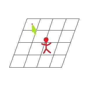 I just wanted to make it clear, but I guess the problem is kind of simple: essentially we're wondering how to find, based on where you've clicked on the screen, exactly which pixel on the map you should be trying to move to. We can use picking to find the specific tile that was clicked on, but otherwise we're a bit confused... we have the location and angle of the camera and the definition of the 2D plane that would represent the appropriate tile, so I feel like it should be possible to find the intersection between the vector defined by the click and the tile, but I guess I'm not sure exactly how to describe the vector. Or maybe this is the wrong way to go about it?
|
|
#
?
Feb 25, 2010 04:50
|
|

|
Martman posted:I'm working on a game engine for a class project (we weren't specifically assigned this project, we chose it, so I don't really see it as an academic integrity issue to get help with this certain issue), and we're using OpenGL. You can use glProject to find the world space vector of the camera click (the function gives you the location on the near clip plane, just subtract the camera position from that). From there, you can use the camera location and that vector to find the intersection with the tile plane. The obvious way to do that would be to find the distance of the camera from the plane (plug the camera location into the plane equation) and then scale the click vector by (that distance / camera vector magnitude) / (cosine of angle between camera vector and plane normal) and add it to the camera position. There's probably a more efficient formula, that's just off the top of my head. haveblue fucked around with this message at 07:09 on Feb 25, 2010 |
|
#
?
Feb 25, 2010 05:50
|
|


|
heeen posted:I have a OpenGL bug that I just can't get a grip on: I render stuff into a fbo, which I can clear to whatever color correctly, but everything I render turns up in white. Where's your draw call? If you disable texturing and lighting and aren't using a shader, vertex colors are used by default by the fixed function shader. The default vertex color is white.
|
|
#
?
Feb 26, 2010 04:08
|
|
|
thepostaldude posted:I am trying to do shadow mapping in OpenGL, but can't really seem to get it right. Judging by how you construct your bias matrix and how you saved your projection*view*model matrix, are you sure you are meaning to do vector*matrix instead of matrix*vector? In other words: code:Also bake your bias matrix into the texture matrix as well instead of constructing it in the shader, but don't do it until everything works.
|
|
#
?
Feb 26, 2010 04:16
|
|
|
I'm using OpenGL's b�zier evaluators, and it breaks for me when I pass in more than 64 control points (8x8 grid) to glMap2f. The maximum amount of control points seems to be implementation specific, but can it really be that low? I'd like to send in 65025 atleast 
|
|
#
?
Mar 2, 2010 17:57
|
|

|
Mata posted:I'm using OpenGL's b�zier evaluators, and it breaks for me when I pass in more than 64 control points (8x8 grid) to glMap2f. The maximum amount of control points seems to be implementation specific, but can it really be that low? I'd like to send in 65025 atleast  I promise you you don't want to use anywhere near that many. A 60,000-degree polynomial will not evaluate to anything sensible. Hell, even 64 terms is overkil for double precision floats. I promise you you don't want to use anywhere near that many. A 60,000-degree polynomial will not evaluate to anything sensible. Hell, even 64 terms is overkil for double precision floats.
Dijkstracula fucked around with this message at 19:25 on Mar 2, 2010 |
|
#
?
Mar 2, 2010 19:23
|
|


|
Dijkstracula posted:
Heh, yeah I forgot how b�zier curves were calculated, even though I read about them this morning which is why I tried to do this (modelling terrain as a b�zier, I tried to make every byte in a 256x256 heightmap a control point  ) )Calling glgetintegerv with GL_MAX_EVAL_ORDER tells you what the max amount of control points you can pass to glMap2f which was 8x8 on my computer.
|
|
#
?
Mar 2, 2010 19:54
|
|
|
I'm asking because I don't know and I'm curious - why are you using bezier curves if you've got a heightmap? It's not obvious to me what your control points will be. Are you sure you don't simply want a run-of-the-mill interpolation/tessellation algorithm instead?
|
|
#
?
Mar 3, 2010 04:24
|
|
|
I'm trying to get rid of this annoying diamond artifact: I believe it's mach banding, but I could be mistaken. It's a heightmap where the worldspace normal is stored in a varying vec3 and then the diffuse color is calculated in the frag shader. Is there a straightforward way of getting rid of this problem? It seems like it should be fairly common.
|
|
#
?
Mar 3, 2010 07:39
|
|

|
Contero posted:I'm trying to get rid of this annoying diamond artifact:
|
|
#
?
Mar 3, 2010 13:57
|
|


|
Dijkstracula posted:I'm asking because I don't know and I'm curious - why are you using bezier curves if you've got a heightmap? It's not obvious to me what your control points will be. Are you sure you don't simply want a run-of-the-mill interpolation/tessellation algorithm instead? I just passed in the height map as the control points in the form of a two dimensional grid of x,y,z coordinate data Here's more about bezier surfaces http://www.opengl.org/resources/code/samples/mjktips/grid/index.html I've since taken a different approach but if I still wanted to render the whole terrain as a bezier surface I'd have to divide it into 4x4 grids and render them one at a time or something like that.
|
|
#
?
Mar 3, 2010 14:06
|
|
|
Mata posted:I just passed in the height map as the control points in the form of a two dimensional grid of x,y,z coordinate data ")
|
|
#
?
Mar 3, 2010 16:37
|
|
|
Contero posted:I'm trying to get rid of this annoying diamond artifact: Can you post a wireframe screenshot? I have a suspicion of what's going on. The most common way of converting the height map to geometry is by making squares out of each four adjacent vertices, then bisecting the squares to form two triangles. However, if you do this, sometimes the bisection direction will run counter to the actual contour of the surface. What you really want to do is calculate the normals of the two triangles in each bisection direction (top-left to bottom-right, and bottom-left to top-right) and find the dot product between them. Then, use the bisection where the dot product is the least (i.e. where the normals are most different). This will ensure that your geometry matches the contours of the underlying terrain as closely as possible.
|
|
#
?
Mar 4, 2010 05:52
|
|
|
Contero posted:Is there a straightforward way of getting rid of this problem? It seems like it should be fairly common. 0 1 2 3 You're doing something like for example, always using (0 1 3) (0 3 2) as the triangles. Don't do this. Instead, alternate which direction the diagonal goes. i.e. if (heightmap x coord + heightmap y coord) is even, use (0 1 3) (0 3 2), and if it's odd, use (0 1 2) (1 3 2) OneEightHundred fucked around with this message at 06:00 on Mar 4, 2010 |
|
#
?
Mar 4, 2010 05:56
|
|
|
Hubis posted:Can you post a wireframe screenshot? I have a suspicion of what's going on. Unfortunately this is from Nvidia's ocean FFT example, and the map is going to change every frame. Changing up my vertex ordering every frame might be a little complicated / slow. OneEightHundred posted:Yes. Right now you're using a diagonal that's always going the same direction, i.e. if you have a 2x2 section of the heightmap representing the points:    I could have sworn you said change the order based on just the Y coord before. It looks less regular, but it's still there. I could have sworn you said change the order based on just the Y coord before. It looks less regular, but it's still there. Here's the code they're using to calculate the normal, if it's at all relevant: code:
|
|
#
?
Mar 5, 2010 01:47
|
|
|
Contero posted:
Something like this: 
|
|
#
?
Mar 5, 2010 05:39
|
|
|
Contero posted:Unfortunately this is from Nvidia's ocean FFT example, and the map is going to change every frame. Changing up my vertex ordering every frame might be a little complicated / slow. Ohhh... for some reason I thought this was a static heightmap. Hmm. Could you just use normals from the normal map instead of using interpolated triangle normals? That would free your lighting model from the underlying geometry division. OneEightHundred posted:No, order by (X+Y), meaning it'll alternate on both axes. You'll still see the artifacts (the underlying problem of the quads being non-planar will remain) but it will reduce the visibility of it.
|
|
#
?
Mar 6, 2010 02:42
|
|
|
Hubis posted:You'll still see the artifacts (the underlying problem of the quads being non-planar will remain) but it will reduce the visibility of it.
|
|
#
?
Mar 6, 2010 04:30
|
|
|
This is a stupid question that I should be able to figure out for myself, but it's just lurking in a blind-spot in my brain and making me crazy. What I have is a hierarchical 'skeleton' object, in which each bone has a length (float) and a rotation (quaternion); when it is animated, a 'recalculate' function is called that recurses its way down the hierarchy setting the appropriate bone positions thusly (where "FullTransform" is the the transformation of meshes that are attached to the bone; they attach to the base of the bone, so they are rotated but not moved up the length, and "FullSubTransform" is the transformation of bones attached to the bone, which are both rotated and translated): code:My problem is how do I calculate this for the third bone - I can't just do primary->length, secondary->rotate, secondary->length, tertiary->rotate, secondary->unlength, primary->unlength, because then the effect of primary->unlength is altered by the tertiary rotate. Nor can I do 1length/2rotate/1unlength, 2length/3rotate/2unlength, because then the tertiary rotation is 2length offset from the base of the primary bone instead of from the base of the secondary bone. Nor can I just find the final bone positions of secondary and tertiary and just perform the additional rotations around those points, because then the rotations are done with untransformed axes of rotation. As I say, I'm pretty sure this should be much easier than I'm making it, I've just got myself stuck in a loop of dumb wrongness. Help! (If the question is unclear, I'll happily answer questions to clarify - I was trying to keep it as succinct as I could.) Edit: actually, I think it probably does need to be clearer. Here is a picture!  If I had an 'arm' mesh, affixed to bone b2 and skinned also onto b3 and b4, and let's say I can get the length and rotation matrices from a member function, the transformation to get the arm into place, assuming the rear end is the root of the skeleton, would be: b1.length * b2.rotation The transformation for a separate forearm object, on b3, if it were unskinned, would be b1.length * b2.rotation * b2.length * b3.rotation The transformation for the b3 'skin' on the b2 'arm', however, must omit that b2.length because we don't want to stretch the arm mesh out, we only want to bend it. But it still wants a rotation around point 2, so it's b1.length * b2.rotation * (b2.length.inverse * b3.rotation * b2.length) And the transformation for the b4 'skin' would be... b1.length * b2.rotation * (b2.length.inverse * b3.rotation * b2.length) * (how the gently caress do I get the correctly transformed rotation around point 3?) Edit2: corrected for doing the length operations in the right direction in the edit, it's still wrong in the original question but pretend it isn't. Edit3: Found the answer myself eventually, guess this thread's pretty useless. roomforthetuna fucked around with this message at 05:53 on Mar 21, 2010 |
|
#
?
Mar 7, 2010 01:29
|
|

|
This is probably a dumb question, but I can't figure out how to do it even after searching google. I am working on improving my iPhone game's performance, and I was wanting to change it from 32-bit textures to 16bit textures. The app uses PNG images with alpha transparency. Here is the current code: EDIT: Had to repack the pixel data apparently. numeric_atrophy fucked around with this message at 05:44 on Mar 21, 2010 |
|
#
?
Mar 21, 2010 05:18
|
|

|
haveblue posted:You can use glProject to find the world space vector of the camera click (the function gives you the location on the near clip plane, just subtract the camera position from that). From there, you can use the camera location and that vector to find the intersection with the tile plane. The obvious way to do that would be to find the distance of the camera from the plane (plug the camera location into the plane equation) and then scale the click vector by (that distance / camera vector magnitude) / (cosine of angle between camera vector and plane normal) and add it to the camera position. There's probably a more efficient formula, that's just off the top of my head. I have a similar problem to Martman, but I'm using XNA. Does anyone know how you find the world space vector for the mouse click? I'm pretty sure I can do the rest from there. Edit: Google has been most unhelpful. I probably don't know what I need to search for. Edit 2: Never mind, here is the solution: http://msdn.microsoft.com/en-us/library/bb203905.aspx HappyHippo fucked around with this message at 20:21 on Mar 22, 2010 |
|
#
?
Mar 22, 2010 01:44
|
|
|
This might be better asked here than the C++ thread: I'm trying to get the square to move to the left and rotate around its center when the d key is pressed twice. It's really simple, I'm just too new at OpenGL to know exactly what I'm loving up. For more context, http://forums.somethingawful.com/showthread.php?threadid=2773485&userid=95987&perpage=40&pagenumber=2#post374137410 Here's the full file: http://pastebin.ca/1848509 I'm trying to, upon hitting d a second time, get the square to launch to the left while rotating about its center. I can only get it to move to the left by manually subtracting from the x coordinates, which isn't translation and won't rotate anything. Removing rectX1 and rectX2 and replacing them with actual numbers does not change the outcome.
|
|
#
?
Mar 22, 2010 09:33
|
|

|
I think you're misunderstanding translation in this context. OpenGL doesn't know where your rectangle was last frame so saying something like "move 0.5 pixels to the right" or "rotates on the x axis at -.75 units" won't get you your expected behavior. You need to tell OpenGL the squares final or "world" position should be each frame. You should probably read into exactly what those glPushMatrix and glLoadIdentity calls are actually doing too because understanding that would probably clear up your confusion on the first part. At any rate, you'll want to keep your squares position and rotation stored somewhere, a global or whatever. Then modify your rectMove function something like this: code:
|
|
#
?
Mar 22, 2010 19:23
|
|
|
Here's a question that's not so much "fix my poo poo" - I gather that DirectX has two ways of doing skinning; one way uses up to four 'system' transformations, and each vertex has weightings for each matrix (with the last one not included because it's 1.0 minus all the others). The other way uses up to 256 transformations, and each vertex has weightings for up to four of them, and four byte-sized indices to indicate which matrices to assign those weights to. Questions about this that I haven't been able to dig up answers to: 1. I'm pretty sure the former method is well supported, but how well supported is the latter? 2. Is there a significant difference in speed between the two methods? 3. If you're rendering a complex object, is it better to have one big mesh with four weights per vertex (most vertices just being 100% on one bone, so the weighting is overkill and unused for many of the vertices), or to render the object as a number of meshes so as to reduce the weighting to two or three per vertex (so there's a separate mesh around each joint), or even to render the object as even more meshes so that blocks which are bound to only a single bone are rendered unweighted, and only the triangles which need their vertices skinned are rendered with weights?
|
|
#
?
Mar 26, 2010 01:46
|
|
|
roomforthetuna posted:1. I'm pretty sure the former method is well supported, but how well supported is the latter? The latter is much more common as far as I know, precisely because you can cram more bones in per draw call. quote:3. If you're rendering a complex object, is it better to have one big mesh with four weights per vertex (most vertices just being 100% on one bone, so the weighting is overkill and unused for many of the vertices), or to render the object as a number of meshes so as to reduce the weighting to two or three per vertex (so there's a separate mesh around each joint), or even to render the object as even more meshes so that blocks which are bound to only a single bone are rendered unweighted, and only the triangles which need their vertices skinned are rendered with weights? If vertex processing speeds are an issue, then consider weight pre-blending. i.e. instead of sending the bone matrices as uniforms, send each unique matrix/weight combination, and index that per-vert instead. SSE can be used to speed this up a bit.
|
|
#
?
Mar 26, 2010 04:19
|
|
|
OneEightHundred posted:D3D9's biggest bottleneck by far is draw calls, and vertex processing is becoming progressively more negligible. Above all else, do as much per draw call as you can.
|
|
#
?
Mar 26, 2010 04:35
|
|
|
krysmopompas posted:As a side-note, if you want to get fancy, http://www.emergent.net/GameFest2008 is an interesting way of bypassing the draw call limitations. Incidentally this sort of thing isn't even new, Quake 3 did it.
|
|
#
?
Mar 26, 2010 04:59
|
|
|
OneEightHundred posted:How is the former even workable with only 4 matrices for the entire mesh?
|
|
#
?
Mar 26, 2010 05:05
|
|
|

|
| # ? Jun 3, 2024 22:18 |
|
|
You should make your data files index weight blends because you can easily convert that to any of the several ways of processing it. I can name at least three major ways of processing skeletal deformation, and indexed weight blends are the only approach that can be trivially loaded as all three. i.e. see AX3SkeletalDeform in this: http://svn.icculus.org/*checkout*/teu/trunk/tertius/docs/tmrf.html?revision=227
|
|
#
?
Mar 26, 2010 05:18
|
|