|
Cosmik Debris posted:converters ... inverters
|
 #
?
Oct 21, 2011 15:31
#
?
Oct 21, 2011 15:31
|
|


|

|
| # ? May 8, 2024 08:41 |
|
|
ANIME AKBAR posted:...the core design is mostly unchanged but I'm just paying far more attention to details, and spending tons of time doing so. It's loving tedious as hell and takes a lot of the fun out of it. But my standards have risen so much that I won't feel satisfied with anything else. It's gotten so bad that I'm considering ordering an Arduino to play with  Engineering a uC solution is pretty time consuming and kind of limits what I can do just based on time constraints. Engineering a uC solution is pretty time consuming and kind of limits what I can do just based on time constraints.
|
|
#
?
Oct 21, 2011 16:34
|
|

|
What do people use to store spare SMD components?
|
|
#
?
Oct 22, 2011 19:56
|
|
|
Unparagoned posted:What do people use to store spare SMD components? Containers meant for beads work pretty well, you can buy them at craft stores like Joann's. For very small stuff you'll probably want special containers like these.
|
|
#
?
Oct 23, 2011 03:44
|
|


|
I'm designing an aquarium controller around an MSP430 and I'd like for it to have some sort of external time source that will let it turn lights on and off on a schedule. I suppose I could just use an RTC source but then I would have to include an interface to actually set the real time. I'd really prefer to use something like GPS that'll just give me a timestamp (though GPS signals don't include a date and that might be helpful). I started looking at small GPS receivers but this particular unit is very much overkill - pretty sure that my aquarium will neither accelerate nor unexpectedly change orientation with magnetic north - and I'm not really sure what all is out there as far as getting a timestamp over the air or where I can search for and find components. Can anyone recommend a simple GPS receiver, a component that can receive WWVB, or something similar? Generally speaking the smaller and easier-to-interface the better; the MSP430 value line isn't suffering from a surplus of memory or IO pins ")
|
|
#
?
Oct 23, 2011 04:16
|
|

|
If you don't want to include an interface to set the time, how are people going to set the times the lights will turn on and off? Just run a real time clock on the chip. It looks simple: http://www.ti.com/lit/an/slaa076a/slaa076a.pdf
|
|
#
?
Oct 23, 2011 05:24
|
|

|
csammis posted:I'm designing an aquarium controller around an MSP430 and I'd like for it to have some sort of external time source that will let it turn lights on and off on a schedule. I suppose I could just use an RTC source but then I would have to include an interface to actually set the real time. I'd really prefer to use something like GPS that'll just give me a timestamp (though GPS signals don't include a date and that might be helpful). http://www.sparkfun.com/products/10060 is what you want, but both SFE and digi-key are out of stock 
|
|
#
?
Oct 23, 2011 07:50
|
|
|
Another option that may work is this little wifi module, again from sparkfun: http://www.sparkfun.com/products/10822 (sold out unfortunately) You can use it to connect to an NTP server through your home network, and have it spit out a text string over serial containing the time. It also has a real time clock running on Unix time which could be used to determine the date with a little bit of work. I'm currently tinkering with this module to get time stamps for a data-logging barometer. I've tried a GPS unit as well but in both cases the handling of the string is really annoying for me. I'm leaning towards a real time clock either in software or on a separate chip. Typical drift of the clock is maybe a few minutes a year, which is pretty good for an aquarium or a barometer
|
|
#
?
Oct 23, 2011 12:48
|
|

|
Corla Plankun posted:If you don't want to include an interface to set the time, how are people going to set the times the lights will turn on and off? That is a good point but this is a build for myself. I am going to program the hour ranges into the chip and if I ever need to change them then it's a quick trip to the Launchpad and back to work. Delta Wye posted:http://www.sparkfun.com/products/10060 is what you want, but both SFE and digi-key are out of stock Why yes that is exactly what I want! I'm in no particular hurry so I guess I can wait until they're stocked someplace again...unless not available for backorder means they're not being made anymore or something? Sandbox posted:Another option that may work is this little wifi module, again from sparkfun: I thought about something like this but having to implement an NTP client alongside the rest of the controller code makes me balk a bit (2k code size). It'd be fun to try though
|
|
#
?
Oct 23, 2011 16:50
|
|
|
csammis posted:That is a good point but this is a build for myself. I am going to program the hour ranges into the chip and if I ever need to change them then it's a quick trip to the Launchpad and back to work. Or you can do this, if you are in MST http://www.sparkfun.com/products/99 It is an RTC that is preprogrammed with the correct time, and only two I/O pins to access it.
|
|
#
?
Oct 23, 2011 17:26
|
|
|
csammis posted:I thought about something like this but having to implement an NTP client alongside the rest of the controller code makes me balk a bit (2k code size). It'd be fun to try though I've considered building a VFD digital clock that would also need somewhat accurate time, my solution would be to use something like a HTTP server that runs NTP and then a PHP script to give the time in a suitable format. If you already have a server running somewhere that'd be the easiest and most reliable solution.
|
|
#
?
Oct 23, 2011 19:42
|
|


|
Unparagoned posted:What do people use to store spare SMD components? We have a bunch of envelopes in boxes. They are kindof ghetto, but can hold reels, cut tape, tubes, or whatever.  
|
|
#
?
Oct 24, 2011 16:16
|
|
|
I'm considering buying a PIC development board and after a lot of looking I think I've found a dev. board that seems to fit the bill: http://www.mikroe.com/eng/products/view/757/easypic-v7-development-system/ It's pretty expensive for a full package with a license for their own software, has anyone got any experience with this board? I want to get a board that can contain all the common devices we typically talk to like temperature sensors, LCDs, buttons, LEDs, external USB, possibly ethernet and bluetooth in the future that can easily be connected to a larger breadboard for larger projects. Critically it needs to support a wide range of controllers since I may want to develop some kind of simple control system on a PIC16F84 or even cheaper but also support a higher end PIC18 with USB and faster math. They also sell mikroC PRO which seems like a pretty neat library and software package, anyone try this? Alternately, anyone know of something more suitable/cheaper? We use a PICDem board in school and it's pretty limited wrt. pretty much everything.
|
|
#
?
Oct 25, 2011 21:51
|
|
|
longview posted:I'm considering buying a PIC development board and after a lot of looking I think I've found a dev. board that seems to fit the bill: Hey! I started learning a little PIC as well, I started from here and I've been having a pretty good time of it. Not going with one of those big rear end expensive boards forces you to learn how to do it all yourself. I knew fuckall about reading datasheets for Microcontrollers and sensors and whatnot and now I feel like I'm at least passable. Wasn't too expensive either. The 18 series is a little pricey but it has a whole hell of a lot of pins and does usb, so there is that.
|
|
#
?
Oct 25, 2011 23:54
|
|


|
Has anyone worked with RF shielding paint? I want to build an RF shielded enclosure for my project, and it seems like the easiest way to go about it is to cover the circuit with some non-conductive material that's easy to work with and then paint over it (and ground it). Amazon sells some of this paint, but it seems marketed towards the "cell phone towers are making me sick" crowd.
|
|
#
?
Oct 26, 2011 05:28
|
|

|
Krenzo posted:Has anyone worked with RF shielding paint? I want to build an RF shielded enclosure for my project, and it seems like the easiest way to go about it is to cover the circuit with some non-conductive material that's easy to work with and then paint over it (and ground it). Amazon sells some of this paint, but it seems marketed towards the "cell phone towers are making me sick" crowd. You can buy standard RF shields that are SMT compatible. Here's an example: http://www.mouser.com/ProductDetail/Laird-Technologies/BMIS-206-C/?qs=sGAEpiMZZMt38gJAVVJmMUETDS21pto6x29%252bIN0pgZM%3d I can't imagine that any "RF paint" would be effective - you need a good solid ground connection to the shield to work well. Just think of the physics behind it - it's not magic. What frequencies are you concerned with shielding? Are you trying to prevent radiated emissions or prevent interference from getting into your circuit?
|
|
#
?
Oct 26, 2011 06:21
|
|
|
SnoPuppy posted:You can buy standard RF shields that are SMT compatible. Here's an example: Yeah, I've seen those enclosures, but I'm needing to shield the traces and amplifier on my circuit board, not a specific component. I have separate antennas on my board that feed into a switch which lets me choose which one to read from. I left one antenna off, and when the switch is set to that missing antenna, there's still a signal being picked up by the traces. Also, my separate amplifier board will pick up my signal without any antennas hooked up. I tried wrapping the amplifier board with tin foil and confirmed that it was electrically connected to ground, but that didn't fix it from picking up the signal by itself. I want to prevent my 3-4 GHz signal from being picked up by anything but a specific antenna on my board to determine the time of flight from the transmitter to a specific position (the receiving antenna). I've gone ahead and ordered a sheet of copper to try making my own enclosure. Krenzo fucked around with this message at 09:39 on Oct 26, 2011 |
|
#
?
Oct 26, 2011 09:27
|
|
|
longview posted:I'm considering buying a PIC development board and after a lot of looking I think I've found a dev. board that seems to fit the bill: I've been using MikroC PRO with a PIC 18F4520 for about a year now and I have no problems with it. My favourite part has to be the in-built libraries (interfacing to an SD card for example). It really is refreshing to be able to write text files to an SD card and forget about the inner workings of it all. Although that line of thinking is fine for a hobbyist like me, I don't know what professionals would have to say about it. I'm slowly learning how to write my own header files, etc. I can't say I've ever used the development boards from Mirkoe, but they should be completely functional. Many of the compiler library examples are written with these development boards in mind. I.e. copy and paste the example into the compiler, compile it, and it works. One thing I would watch out for: limited access to certain PIC pins. I.e. the peripherals on the board may be hardwired and there could be a conflict if you want to use button X with buzzer Y and they both share a pin. I'm pulling that problem out of my rear end though. I'll agree with Burritos that the DIY/breadboard approach can be rewarding, while time consuming. Depends on what you're after. I've recently upgraded to the MikroC PIC32 compiler, which I've paired with a chipKIT Uno32 board. The chipKIT is pretty much a clone of a standard Arduino board but features a PIC32MX. I don't care for the Arduino stuff so the MikroC compiler acts as a *very* capable replacement. Couldn't be happier with it. The cost of the Uno 32 was around 40 dollars AUD, making it a no-brainer for someone that wants ever more powerful chips to tinker and play with. Cost effective to turn an LED on and off with a 32 bit micro? Probably not, but I don't ever plan to do production runs of circuits. Gotta say that the PIC32 compiler is *not* cheap, which might be a deterrant to some. Glad to answer specific questions (as best I can) about the MikroC PRO compiler if you have them.
|
|
#
?
Oct 26, 2011 11:37
|
|
|
Tres Burritos posted:Hey! I started learning a little PIC as well, I started from here and I've been having a pretty good time of it. Not going with one of those big rear end expensive boards forces you to learn how to do it all yourself. I knew fuckall about reading datasheets for Microcontrollers and sensors and whatnot and now I feel like I'm at least passable. Wasn't too expensive either. The 18 series is a little pricey but it has a whole hell of a lot of pins and does usb, so there is that. I definitely agree that walling myself into a program like Flowcode isn't the way to learn microcontrollers, yes. In school we just started programming PIC18s in assembly, it works but I wouldn't want to do anything involving math or strings so something I can program in C would be nice. The reason I found the Microelektronica board interesting is I want a board that makes hooking up a few buttons and maybe a LCD easy so I don't have to permanently dedicate a breadboard to it. Suppose I just put a MCU on its own breadboard, what's a good ICSP device to use with just a controller? It needs to be able to at least program the controller, preferably run debugging with MPLAB, and USB is necessary since I often program on the laptop. In other news I was able to use the Logic analyzer for a real project yesterday, I needed to interface with a serial VFD character display, incredibly useful device that. But the VFD display only works if I connect a logic probe to the data line, but not the clock or enable lines. It plain won't acknowledge anything unless I have the probe connected, it's connected using some wires going from the Arduino to the dupont connector, and reducing the data rate didn't do anything. E: going from the MCU to the breadboard and then to the display seems to have solved it... 
longview fucked around with this message at 11:52 on Oct 26, 2011 |
|
#
?
Oct 26, 2011 11:50
|
|
|
Those conductive polymer paints are reasonable in principle; you just need to make sure the layer is thick enough to be a couple skin depths deep (though I don't see any specs on the conductivity of the paint, which makes determining that difficult). I've never used the paints, but I have used conductive plastic enclosures based on the same stuff and they work okay for prototypes.Krenzo posted:Yeah, I've seen those enclosures, but I'm needing to shield the traces and amplifier on my circuit board, not a specific component. I have separate antennas on my board that feed into a switch which lets me choose which one to read from. I left one antenna off, and when the switch is set to that missing antenna, there's still a signal being picked up by the traces. Also, my separate amplifier board will pick up my signal without any antennas hooked up. I tried wrapping the amplifier board with tin foil and confirmed that it was electrically connected to ground, but that didn't fix it from picking up the signal by itself.
|
|
#
?
Oct 26, 2011 13:03
|
|
|
ANIME AKBAR posted:If you're getting poorer than expected isolation on a switch, then consider using striplines instead of microstrips, or use a different switch or something. The switch isolation is fine. I measured this by touching a conductor to the switch pins and seeing that the attenuation matched the datasheet. The problem is that my microstrip traces before the switch (for the enabled switch path), after the switch, and in my amplifier are picking up the transmitted signal instead of just the antennas placed before the switch. I would like to try using striplines. However, I've been going through ExpressPCB, and their software sucks. Any real PCB software I've tried is just a nightmare to work with.
|
|
#
?
Oct 26, 2011 18:08
|
|
|
Krenzo posted:The switch isolation is fine. I measured this by touching a conductor to the switch pins and seeing that the attenuation matched the datasheet. The problem is that my microstrip traces before the switch (for the enabled switch path), after the switch, and in my amplifier are picking up the transmitted signal instead of just the antennas placed before the switch. Do you have via walls around your RF traces? What's your trace to trace space vs height above ground plane? If you're trying to isolate the whole assembly, I'd probably just put it in a metal box with the connector poking out. Make sure to have exposed ground on all sides of your board, so that it can make good contact with the metal box (ideally it would be clamped in place, but a few plated screw holes might work well enough). Microstrip should be just fine - in fact, it can be better since it doesn't require any via transitions. Those can really mess up a signal - even 32 mils at 10 GHz is like a 15 deg stub. Plus the impedance discontinuity of the actual via. Depending on your frequencies though, I would void the solder mask above your RF traces. Personally, I would just bite the bullet and learn something like eagle or one of the more powerful tools. It will make life easier in the long run.
|
|
#
?
Oct 26, 2011 18:33
|
|
|
SnoPuppy posted:Do you have via walls around your RF traces? What's your trace to trace space vs height above ground plane? No, I do not. There's one point where two traces come within 25 mils of each other for a length of 100 mils, and the height above ground is 12 mils. SnoPuppy posted:If you're trying to isolate the whole assembly, I'd probably just put it in a metal box with the connector poking out. Make sure to have exposed ground on all sides of your board, so that it can make good contact with the metal box (ideally it would be clamped in place, but a few plated screw holes might work well enough). Striplines sound like the easier way to go though. Then I would only have to worry about isolating my components and not the traces. SnoPuppy posted:Personally, I would just bite the bullet and learn something like eagle or one of the more powerful tools. It will make life easier in the long run. No other pcb manufacturer comes close to their price though.
|
|
#
?
Oct 26, 2011 19:18
|
|
|
Whoops, that post was meant for another thread. Though.. on the same bench.. (in case you still want to look at a tiny airplane: http://forums.somethingawful.com/showthread.php?threadid=3125553&pagenumber=48#lastpost ) While at the hacker space last night I wanted to test where my little inverter would cut out.  I used a soldering iron as a load.  An adjustable PSU, and some meters goes a long ways. So, with 8v input:  That's really ugly. And it registered as 130vac on my voltmeter. And with 12.6v input:  Still really ugly, but at least the modified SIN wave is still the right shape. I think i'm going to suck it up and just put good Nimh to power it instead of trying to do the LiIon conversion I was planning. Nerobro fucked around with this message at 20:04 on Oct 26, 2011 |
|
#
?
Oct 26, 2011 19:56
|
|

|
Krenzo posted:No other pcb manufacturer comes close to their price though. There are some Chinese companies that make boards incredibly cheap. There was a discussion a few pages back.
|
|
#
?
Oct 26, 2011 20:36
|
|
|
taqueso posted:There are some Chinese companies that make boards incredibly cheap. There was a discussion a few pages back. All of the good deals were for 2 layer boards. The only one I saw that does 4 layers at a good price (dorkbotpdx) has a longer wait time.
|
|
#
?
Oct 26, 2011 20:59
|
|
|
Krenzo posted:The switch isolation is fine. I measured this by touching a conductor to the switch pins and seeing that the attenuation matched the datasheet. The problem is that my microstrip traces before the switch (for the enabled switch path), after the switch, and in my amplifier are picking up the transmitted signal instead of just the antennas placed before the switch. quote:I would like to try using striplines. However, I've been going through ExpressPCB, and their software sucks. Any real PCB software I've tried is just a nightmare to work with. For four layer boards, the best you can do it probably advanced circuit's 66 each deal, if you're a student anyways. At GHz frequencies you can't really afford to be too cheap, especially if you need decent VSWR and low loss. But snopuppy does have a point; striplines can cause a lot of issues if you don't know what you're doing. If you don't have a lot of resources at your disposal (good instrumentation, money to make mistakes with, good simulation software) then I wouldn't recommend it.
|
|
#
?
Oct 27, 2011 03:01
|
|
|
ANIME AKBAR posted:So wait, you're transmitting and receiving signals simultaneously, at the same frequency? What are you actually making? The circuit we're discussing is only receiving. It has multiple antennas spread out on it. Think of it like GPS, but instead of having one receiver (GPS unit) and multiple transmitters (satellites), I have one transmitter circuit that's completely separate and placed at a distance. Then, I have multiple antennas all built onto the same circuit board with switches determining which antenna is active. My receiver is going to use the time of flight to each individual antenna on the board to determine the location of the transmitter. I need each individual antenna to only give me the signal from that exact location to be able get an accurate location of the transmitter. ANIME AKBAR posted:Eagle is quite easy to use. I'm no longer a student, and even when I was a student, I didn't want to go through the hassle of getting it shipped to a university address. After thinking it over, I'm going to put all of the elements that need to be unshielded (the antennas) on the backside of the board and all of the shielded components including microstrip traces on the frontside with vias connecting to the antennas. Then, I'll shield the frontside with an enclosure and with a solid ground layer beneath. I just don't know if the antennas will tolerate a ground layer underneath (destructive interference/reflections?) as that's contrary to the suggested floor plan in their datasheet, but I fully accept that the antennas will not receive a signal through the ground plane.
|
|
#
?
Oct 27, 2011 05:28
|
|
|
longview posted:I definitely agree that walling myself into a program like Flowcode isn't the way to learn microcontrollers, yes. C compiler for pic 18 series + PICKit3 = 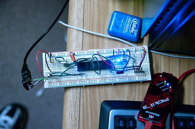 ? If you're good at breadboarding and tidy and poo poo you could make it look cleaner / nicer.
|
|
#
?
Oct 27, 2011 20:28
|
|
|
hey I'm having a bitch of a time with a board I just got, it's got a wierd short circuit thing going on, which I'm pretty sure is either a problem with the board or the soldering to the board, but just in case I was wondering if any of you could spot anything crazy wrong with this schematic.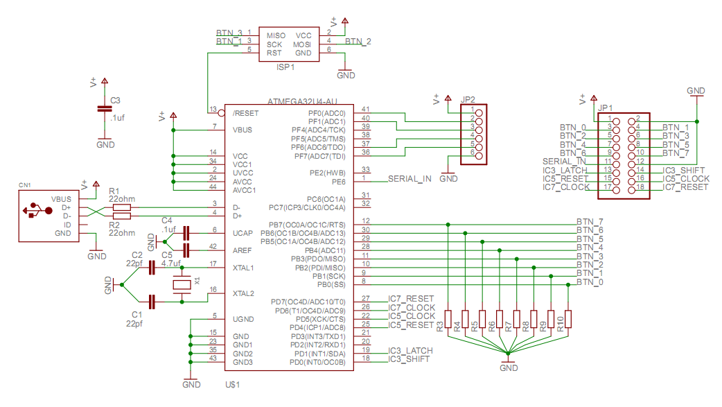
|
|
#
?
Oct 27, 2011 22:54
|
|

|
Have any of you guys used any of those portable digital DSOs that tend to pop up on ebay quite a bit? Are they any good?Krenzo posted:After thinking it over, I'm going to put all of the elements that need to be unshielded (the antennas) on the backside of the board and all of the shielded components including microstrip traces on the frontside with vias connecting to the antennas. Then, I'll shield the frontside with an enclosure and with a solid ground layer beneath. I just don't know if the antennas will tolerate a ground layer underneath (destructive interference/reflections?) as that's contrary to the suggested floor plan in their datasheet, but I fully accept that the antennas will not receive a signal through the ground plane. I'm still not following what you're trying to do. It sounds like you're trying to "shield an antenna", which would prevent it from ever working. Anything that breaks out of the shielded environment (such as your antenna feedpoint) is going to pick up some amount of RF.
|
|
#
?
Oct 28, 2011 05:17
|
|

|
Yaknow, the images from the oscilloscope posted like eight or ten posts up is from my DSO nano. It works just fine. Just it's not very fast. 1 meg samples means it's really only good to 100khz. 200khz if you don't care with only 5x oversampling. It's incredibly handy to have. But it's not very capable.
|
|
#
?
Oct 28, 2011 06:43
|
|
|
loving Richards controllers, how do they work!
|
|
#
?
Oct 28, 2011 07:09
|
|

|
Cyril Sneer posted:I'm still not following what you're trying to do. It sounds like you're trying to "shield an antenna", which would prevent it from ever working. Anything that breaks out of the shielded environment (such as your antenna feedpoint) is going to pick up some amount of RF. I'm not trying to shield the antenna. I'm trying to shield the microstrip traces that carry the signal from the antenna to a switch, then through a filter, and then to an amplifier.
|
|
#
?
Oct 28, 2011 07:38
|
|
|
Cyril Sneer posted:Have any of you guys used any of those portable digital DSOs that tend to pop up on ebay quite a bit? Are they any good? I've got a DSO Quad on order now, the spec says it *should* do something crazy like 36 MHz but I've read it tops out at around 1 MHz due to input buffer design problems. It seems really handy but there's no way I'd want one as my only oscilloscope (I love my 70s HP). Regardless I'll do some measurements and report back when I have it, I'll also investigate any hardware hacks to improve frequency response (some people reported greatly improved bandwidth by changing some values in the feedback circuit) and the quality of the triggering circuit (apparently software based for anything but edge-triggering). I hope to use it in conjunction with my Logic for MCU development. Tres Burritos posted:C compiler for pic 18 series + PICKit3 longview fucked around with this message at 09:42 on Oct 28, 2011 |
|
#
?
Oct 28, 2011 09:38
|
|
|
Krenzo posted:I'm not trying to shield the antenna. I'm trying to shield the microstrip traces that carry the signal from the antenna to a switch, then through a filter, and then to an amplifier. But also you think that the signal is leaking into the traces after the switches. How are you determining this? What makes you think that it's being coupled to those traces directly, instead of through the switch?
|
|
#
?
Oct 28, 2011 14:53
|
|
|
ANIME AKBAR posted:Yeah, but this doesn't really make sense. The most of the signal that ends up on those traces from the antennas is there because they're attached to antennas, which I assume are supposed to pick up the signal. Shielding those traces won't change that. I'll add to this, what switch are you using? It can be difficult to find a good switch with high isolation, especially if you're operating above 4 GHz.
|
|
#
?
Oct 28, 2011 19:06
|
|
|
ANIME AKBAR posted:Yeah, but this doesn't really make sense. The most of the signal that ends up on those traces from the antennas is there because they're attached to antennas, which I assume are supposed to pick up the signal. Shielding those traces won't change that. Hmm, I'm not really sure how to explain things differently. My problem is how if you have an antenna that goes to a 3 ghz high pass filter and then to an amplifier. The filter removes all unwanted signals below 3 ghz. If you have an unshielded connection from the filter to the amplifier, then that connection is going to pick up those unwanted signals again and be amplified. They'll end up in the sampled signal. If the connection from the filter to the amplifier is shielded, then no unwanted signals can be picked up between the filter and amplifier because they could only be picked up before the filter which removes them. I'm trying to shield the connection between the antenna and the various components on the pcb so that only signals are picked up by the antenna. ANIME AKBAR posted:But also you think that the signal is leaking into the traces after the switches. How are you determining this? What makes you think that it's being coupled to those traces directly, instead of through the switch? I made an open circuit between the antenna and the switch. It still picked up the signal with the switch set to that antenna. I then disconnected the whole antenna pcb board from my amplifier. The amplifier is just a separate eval board, and that picked up and amplified the signal with no input connection/cable attached. Therefore, if the unshielded amplifier pcb can pick up the signal, then it must be getting picked up directly by the traces on the pcb. SnoPuppy posted:I'll add to this, what switch are you using? http://www.skyworksinc.com/uploads/documents/200914H.pdf Krenzo fucked around with this message at 21:11 on Oct 28, 2011 |
|
#
?
Oct 28, 2011 21:02
|
|
|
I'm going to respond to your post in reverse order, as I think that'll make mroe senseKrenzo posted:I made an open circuit between the antenna and the switch. It still picked up the signal with the switch set to that antenna. I then disconnected the whole antenna pcb board from my amplifier. The amplifier is just a separate eval board, and that picked up and amplified the signal with no input connection/cable attached. Therefore, if the unshielded amplifier pcb can pick up the signal, then it must be getting picked up directly by the traces on the pcb. Its not enough to just say "it picked up the signal". This isn't surprising at all - ANY conductor is going to pick up some amount of RF. The question is how well is your circuit rejecting the unwanted signal relative to the desired signal. Its not a yes/no situations. Its "is the unwanted signal low enough that it doesn't affect the performance of the system". Again, you are ALWAYS going to pick up some stray signal. Krenzo posted:Hmm, I'm not really sure how to explain things differently. My problem is how if you have an antenna that goes to a 3 ghz high pass filter and then to an amplifier. The filter removes all unwanted signals below 3 ghz. If you have an unshielded connection from the filter to the amplifier, then that connection is going to pick up those unwanted signals again and be amplified. They'll end up in the sampled signal. If the connection from the filter to the amplifier is shielded, then no unwanted signals can be picked up between the filter and amplifier because they could only be picked up before the filter which removes them. Right, so you're trying to isolate the post-filtered circuitry from the external RF environment to minimize the re-introduction of noise. I don't know what your design requirements are, but is there any reason you can't use semi-rigid coax to connect your amp/filter/antenna together?
|
|
#
?
Oct 29, 2011 18:25
|
|
|

|
| # ? May 8, 2024 08:41 |
|
|
Accidentally bought a PIC18F4450 instead of a PIC18F4550, but I can't find any code for this model and I can't get the drat thing to work. I tried using some code for the 4550 from here and here, and I can get the code to compile and download onto the pic without any errors, but no matter how I modify the code none of the outputs on will turn on. I don't know if I'm missing some part of the config or if I fried the thing or what. Anybody have any ideas?
|
|
#
?
Oct 30, 2011 00:48
|
|