


|
Hypnolobster posted:Note that these only work when you're measuring one leg. If you just clamp it around two conductors carrying a hot and neutral it won't work. Yeah, you have to measure one leg at a time; the magnetic fields from a hot and neutral will perfectly cancel out and read 0 amps. Incidentally, this is precisely how GFCIs work- they clamp the line(s) and neutral simultaneously, and if any current escapes via ground fault, it shows up an an imbalance, and the GFCI trips.
|
 #
?
Nov 22, 2011 23:58
#
?
Nov 22, 2011 23:58
|
|


|

|
| # ? May 9, 2024 05:29 |
|
|
Dragyn posted:Thanks for the feedback. Part of my loan program requires an inspection, so I don't have a choice there anyway. Cool. It's good that your boiler doesn't require 240; two-pole switches can be hard to find. Is this circuit just to run a combustion air fan or something? I'm curious as to the nameplate draw of a boiler.
|
|
#
?
Nov 24, 2011 01:13
|
|


")
|
babyeatingpsychopath posted:Cool. It's good that your boiler doesn't require 240; two-pole switches can be hard to find. Is this circuit just to run a combustion air fan or something? I'm curious as to the nameplate draw of a boiler. I'm not expert in that sort of thing, but it's a forced water system and I think that the role of the electricity is simply as a pilot light and possibly a water pump to circulate. I actually ended up having the electrician take care of it (thought I did do the wiring from the panel to the rafter. Turns out permits are about $80 in my town and after the cost of that, the materials and having to deal with the inspector if something was wrong, the electrician was worth the money. It looks nice and professional too, he put in EMT. Turns out my plumber didn't drain the water from the tank on the old boiler, so when I started to dismantle it today, I ended up being the little Dutch boy with his finger in the dam for a while to stop ~50 gallons of nasty water from pouring into my basement.
|
|
#
?
Nov 24, 2011 02:26
|
|

|
Probably a good choice. I don't mind giving people electrical advice but sometimes I worry that they are going to get in over their head and end up spending a lot more then it would cost to have an electrician come deal with it.
|
|
#
?
Nov 24, 2011 03:00
|
|
|
grover posted:Incidentally, this is precisely how GFCIs work- they clamp the line(s) and neutral simultaneously, and if any current escapes via ground fault, it shows up an an imbalance, and the GFCI trips. This is a really cool and simple concept. Thanks for stating it so clearly. I knew what they did but never understood how brilliantly simple the concept is. How does an AFCI do what it does? Do any of these things use microprocessors yet? I've been really impressed with the AFCI breakers on my new home. They've never ever tripped when something funny wasnt happening. Closest I've had to an odd trip was actually a nearby lightning strike the other day. Sent just one of them into arcfault state and cut off that circuit. Inducted current? Nothing else in the house was affected and the power didnt even surge or go out as a whole.
|
|
#
?
Nov 24, 2011 05:24
|
|
|
chedemefedeme posted:This is a really cool and simple concept. Thanks for stating it so clearly. I knew what they did but never understood how brilliantly simple the concept is.
|
|
#
?
Nov 24, 2011 13:47
|
|
|
My house has the older type of wiring that lacks a ground, which I obviously want to replace. I understand how to fish the wire throughout the house and rewire each receptacle but I'm at a loss when it comes to the service panel. How do I replace the wiring that comes directly out of the service panel? Also, what are some things I need to know when I take the face plate off of the service panel?
|
|
#
?
Nov 25, 2011 01:26
|
|
|
masada00 posted:My house has the older type of wiring that lacks a ground, which I obviously want to replace. I understand how to fish the wire throughout the house and rewire each receptacle but I'm at a loss when it comes to the service panel. How do I replace the wiring that comes directly out of the service panel? Also, what are some things I need to know when I take the face plate off of the service panel? That doesn't automatically disqualify your system not being grounded... I managed to convert my house built in 1956 to grounded receptacles with barely fishing any cable at all. Do you have metal conduit? That isn't common in older homes (or new ones) but I have seen it before and it is a legal grounding method. One way that electricians grounded steel boxes in the past was to bend the grounding wire back out the box entrance and attach it on the outside of the steel box via the gang screws. Half of my own home was like this. You can check for this by getting a cheap $2 circuit tester, taking a face plate off and testing for a circuit between the shorter receptacle slot and the steel box. Yet another way electricians wired things in the past was to actually use NM cable with ground, but not hook up the ground wire. The other half of my home was like this. If possible, look in your boxes and see if you can find any with the outer NM covering still on where you can reach it. Use some wire cutters and peel back the outer covering a bit. Push aside the paper insulators and look for a bare ground wire. If you find one, you might be able to tug on it with a pair of pliers and pull out a good inch, enough to pigtail off of. In my home's old romex, the ground wire was actually bent zigzagged inside, so by tugging on it, I managed to straighten out an inch for pigtailing. As for the panel, the biggest safety tip is to shut off the main breakers first, before you even open it up. The next biggest tip is to never touch the hot busbars inside. The cables that aren't in conduit that go into the panel must be clamped. Older boxes will use metal clamps where you have to remove the two screws on the clamp on the outside of the box in order to free the cable so you can pull it out. If your panel is in a finished wall, that means tearing down the drywall/plaster around it. If you need to remove the metal clamp from the box, there's a big nut on the inside of the box. Nowadays there are also plastic clamps which just snap into the hole and hold the cable with a plastic spring. If this is the main panel, neutrals and grounds can be on the same busbars. If it's a subpanel, they must be attached to their respective busbars. Nevertheless, most electricians wire up neutrals and grounds to their respective bars anyway, then bond those 2 busbars together with their connecting rod.
|
|
#
?
Nov 25, 2011 02:21
|
|
|
This thread has inspired to saftey-a-fy my house when it comes to electricity. So I've developed a plan and picked up an outlet analyzer 1. I had 2 outlets reversed in the kitchen, I am thinking that it could have been very bad had I plugged in my metal 1950s vacuum cleaner or a metal lamp. I. Switched them around next day. (drat person who put them in couldn't read I guess, or leave me more than 2in. of wire outside the box to work with 2. I have 2 outlets near the sink that are not gfci I am assuming that they both need to be, that I cannot daisy Chain them like in a living room. 3. Bathroom needs gfci too! (but hey at least it's a 3prong with ground, if I remember from 2 days ago) 4. Living room and dining room need gfci and some 3prong outlets installed. All the new outlets will be tamper resistant and I will replace the rest on a room by room basis. Also I have 2 ground rods on opposite ends of the house, 1 looks like it may be for phone only,. The other is for my panel, both are slightly exposed, should I hit them with a sledge? Also I have a small 30 panel (It's 2 30a breakers labeled 30 joined together to the garage. I am currently running 3 circuits, side 1 garage door and single light fixture, side 2 garage door and single light fixture, and one for all outlets. I assume that this is too small for a 240v. Also why the gently caress not spend the extra $ for higher amperage? I mean even at a buck or two a foot extra its cheaper than digging up conduit and replacing everything because the next owner knows how to use tools.
|
|
#
?
Nov 29, 2011 05:43
|
|


|
I realized something when out in the laundry room. My house, at least out there in that room, has the fire stops/horizontal 2x4's/whatever you call them between studs at about the 5 foot level. If this is true, how hosed am I regarding rewiring? We're on cloth 2 wire here and not a ground in sight, with a 60amp service and an 8-fuse panel. I want to rewire it over the next few months but fear that once I get the old wire out, I won't be able to drop the new stuff. Runs would all be done from the unfinished attic. My nightmare is if they overbuilt this thing (as it appears to have been so far) and actually stapled the old wire to the studs before drywalling. If so, this house may be boned. 
|
|
#
?
Nov 30, 2011 16:49
|
|


|
tater_salad posted:..GFCI stuff.. Assuming you read on what i say below and you arent just assuming a lack of gfci, but have actually tested it, It's kindof amazing your freaking bathroom lacks GFCI. Are you sure you don't just have one in one bathroom that shares the circut with your other bathroom or something? I know my childhood home was built like that. A GFCI in one bathroom ran outlets in another one. Are you saying you dont have GFCI because you dont see the ground fault outlet or because your tester produced a ground fault and nothing happened? Regular outlets can be put in line behind the protection of a GFCI if properly wired. This allows you to have a kitchen with multiple outlets without them all having to be actual GFCI sensing devices. You just install one actual GFCI and wire the other normal outlets through the GFCI properly and they all are ground fault protected. I believe recent code states you can no longer share indoor/outdoor GFCI circuits with each other, but you may still chain normal outlets behind a GFCI outlet to produce one room of ground fault protected outlets. I believe you are also supposed to affix a small label to any normal outlet that is done this way that states it is ground fault protected. Just giving you that info to be sure you arent seeing normal outlets and assuming they are unprotected. If your kitchen is wired properly, your normal outlets may be ground fault protected. If it was wired where this is not the case then it may be easier to install an actual GFCI outlet in each normal outlet's place than it would be to redo the wiring. For bedrooms/livingrooms it is properly vastly preferable to install an AFCI+GFCI breaker on that circuit instead of installing GFCIs at every outlet, or trying to find the first one in line and rewiring where all behind it fall under its protection. AFCI is now code for new construction and retrofit in many places because it offers you protection GFCI can not that is particularly applicable to bedrooms and living rooms. While ground fault protects you only from current escaping your circuit and going to ground (think touching a light socket while standing in water) arc fault protection is mainly about fire prevention (think melting wire on a light strand in your christmas tree). An arc from hot to neutral will not always trip a GFCI or a normal breaker before it causes a smouldering fire. It will very quickly trip an AFCI breaker, usually before it can get hot enough to flare. Installing at the breaker of course has the ease of popping it in one place and being done with it; no fooling around in the outlets in your house required. Take caution; I am not an electrician, just a dude who knows a lot. Consult an electrician if you are not confident and comfortable with what you're doing. Know that in some countries it is illegal to do your own electrical work. Know that you dont get away with the easy breaker swap in all situations as you may not have proper ground wiring in your house or something could be wired totally whack. Be familiar with your setup before you modify it. Blah blah blah.
|
|
#
?
Nov 30, 2011 18:38
|
|
|
The only gfci outlet in have is the one I replaced outside for Christmas lights this year (the old was dead), oh and the one in the crawl space that's for the sump pump. No gfci breaker as far as I can tell as those usually have a test button on them. My outlets are not the strong point of the house
|
|
#
?
Nov 30, 2011 19:33
|
|
|
chedemefedeme posted:Installing at the breaker of course has the ease of popping it in one place and being done with it; no fooling around in the outlets in your house required. Eh, they aren't completely easy... You still have to root around and find the neutral that goes with the hot for that branch, disconnect it from the neutral busbar and bend it around to go into the new GFCI breaker, then connect the GFCI's curlyque neutral pigtail to the busbar. GFCI breakers also cost the same as 4 or 5 GFCI receptacles.
|
|
#
?
Nov 30, 2011 23:35
|
|
|
Jonny 290 posted:I realized something when out in the laundry room. My house, at least out there in that room, has the fire stops/horizontal 2x4's/whatever you call them between studs at about the 5 foot level. you're not hosed, but you'll have quite a bit of sheet rock repair to do if that's the case. if you're coming from the top cut a hole ABOVE where the blocking in the wall is and drill down through it. then when you send the wire down from the attic fish it through the second hole and down to where the plug/switch will be. then patch up and paint the sheet rock. a bit more money in repair work but well worth it in the long run. if all of the old wiring is stapled and you can't pull it out, either put it back into the new box and cap it off or if you're completely updating the service and rewiring and not using ANY of the old wire and are 100% certain it's no longer energized just abandon it in the wall and cut out any of the old exposed wires in the attic/crawlspace/wherever so no one can use them later.
|
|
#
?
Dec 1, 2011 05:22
|
|

|
chedemefedeme posted:For bedrooms/livingrooms it is properly vastly preferable to install an AFCI+GFCI breaker on that circuit instead of installing GFCIs at every outlet, or trying to find the first one in line and rewiring where all behind it fall under its protection. AFCI is now code for new construction and retrofit in many places because it offers you protection GFCI can not that is particularly applicable to bedrooms and living rooms. While ground fault protects you only from current escaping your circuit and going to ground (think touching a light socket while standing in water) arc fault protection is mainly about fire prevention (think melting wire on a light strand in your christmas tree). An arc from hot to neutral will not always trip a GFCI or a normal breaker before it causes a smouldering fire. It will very quickly trip an AFCI breaker, usually before it can get hot enough to flare.
|
|
#
?
Dec 2, 2011 03:09
|
|
|
crocodile posted:you're not hosed, but you'll have quite a bit of sheet rock repair to do if that's the case. if you're coming from the top cut a hole ABOVE where the blocking in the wall is and drill down through it. then when you send the wire down from the attic fish it through the second hole and down to where the plug/switch will be. then patch up and paint the sheet rock. a bit more money in repair work but well worth it in the long run. Fair enough, good points. I guess I could just go buy a sheet of sheetrock and make a cutout template and just cut prefab patches to fit that template, that way I could just slice out an access hole using my cutout template, drill, patch and go. It will be a complete rewire starting on my side of the utility shutoff, I want to reuse nothing. Related, what's it going to take to coordinate this with the power company? I am sure it is not a good idea to bring a house from 60A to 200A service without upgrading the feed/cutoff switch. Jonny 290 fucked around with this message at 12:36 on Dec 2, 2011 |
|
#
?
Dec 2, 2011 12:34
|
|
|
Jonny 290 posted:Related, what's it going to take to coordinate this with the power company? I am sure it is not a good idea to bring a house from 60A to 200A service without upgrading the feed/cutoff switch. And yeah, the wiring is required to be stapled to the studs, so you're not likely to be able to pull it out and will have to abandon some in-place. Fortunately for you, there is an allowance to fish cabling through walls for retrofit work; you're only required to staple where accessible (like in the attic or unfinished basement, or if you removed drywall.) You can buy special super-long flexible drillbits to cut through studs, there's a lot of info on the web about it.
|
|
#
?
Dec 2, 2011 12:48
|
|
|
Very good information. It's a really daunting task, but I don't want to let the wiring get any older. And I'd like to have a properly grounded system for all my computer and radio gear; neutral in my radio room floats about 10V above earth, give or take, so I have to be extremely careful to never use old equipment which connects neutral and earth through the chassis or something. I've seen those flexi bits and they look great for the interior walls. For the outlets on exterior walls (not enough attic clearance to use those bits on the exteriors), well, I think there's just going to be a shitload of sheetrocking going down. Jonny 290 fucked around with this message at 13:05 on Dec 2, 2011 |
|
#
?
Dec 2, 2011 13:03
|
|
|
Sorry if this isn't quite right for this thread (it's more general mains electricity than wiring), but I was wondering: Are those lamp socket adapters, like this one, safe to use? I'm planning on using it with an aquarium pump (with no ground plug) that should draw less than 5 watts, but I'd probably need to use an extension cord. It'd be outdoors.
|
|
#
?
Dec 2, 2011 16:41
|
|


|
TVarmy posted:Sorry if this isn't quite right for this thread (it's more general mains electricity than wiring), but I was wondering: Are those lamp socket adapters, like this one, safe to use?
|
|
#
?
Dec 2, 2011 17:08
|
|
|
Jonny 290 posted:Very good information. It's a really daunting task, but I don't want to let the wiring get any older. And I'd like to have a properly grounded system for all my computer and radio gear; neutral in my radio room floats about 10V above earth, give or take, so I have to be extremely careful to never use old equipment which connects neutral and earth through the chassis or something. It is a very daunting task. Get access to the 2011 NEC (code book). Read all of article 210: Branch Circuits and 220: Branch Circuit Calculations. In article 210, it tells you EVERY outlet your house is REQUIRED to have, and what can be on it. You can put more, but this is the minimum. In article 220, it tells you how much load your house will draw, and from where. Using these two pieces of information, you can go to the power company and ask for the proper-sized service. You also go to the permitting department and get the proper permit. You may end up with a 200A service. These things happen. You may also end up with a $2000 permit. Around here, there's a fee based on service size, plus an additional small fee per new outlet if you're doing remodel. So completely remodelling a house adds up fast. $200 for the service, plus $4 for each outlet can very quickly turn into a few thousand dollars. After you know what you're getting into, see if you can figure out what your grounding requirements are. They may be very simple (a ground rod) or they may be very annoying (two ground rods in a trench 20' long with #2 bare copper between them, plus any other grounding method, plus interconnect all non-gas metallic piping, oh, and supply a bond point for all low-voltage systems within 10' of their entrance point). Finally, figure out if you're allowed to do this yourself. I've lived in four states that allowed homeowners to pull their own "homeowner" permit, and do all the work themselves, with various levels of oversight. I also know there are places where changing anything in the main panel or adding/removing more than 2 outlets requires a licensed electrician. Good luck! You can do this. Edit: note: This is what I did when I completely rewired my house about 5 years ago. After that, I found out how easy and fun electrical work was, and became an electrician. Now I have my license, and it's still easy and fun. babyeatingpsychopath fucked around with this message at 17:43 on Dec 2, 2011 |
|
#
?
Dec 2, 2011 17:38
|
|
|
I'm installing a ceiling fan. The wiring: House: Green Red Black White Fan: Green Blue Black White I'm installing without a remote so it says to connect the blue and black to the black on house, no prob. Green to green, no prob. White to white, no prob. But what should I do with the red from the house? Thanks!
|
|
#
?
Dec 2, 2011 19:56
|
|
|
Socratic Moron posted:I'm installing a ceiling fan. The wiring: That's probably there for if you had a fan/light combo that could be turned on and off independently. Open up the corresponding switch to see. It could also be a three way switch, though, which is why you need to check. If it is, there are a couple possibilities for how it is wired: http://www.wfu.edu/~matthews/courses/p230/switches/3way/variations.html
|
|
#
?
Dec 2, 2011 20:37
|
|

|
jackyl posted:That's probably there for if you had a fan/light combo that could be turned on and off independently. Open up the corresponding switch to see. It could also be a three way switch, though, which is why you need to check. If it is, there are a couple possibilities for how it is wired:  So I took that off and wired it according to instructions and simply capped the red wire with a wire nut. The fan and light works, though there was an initial "pop" when I turned things on the first time. Think it's ok or should I investigate further? There's only the one light switch in the room, so I can't see it being a three way. Thanks for your help, I really appreciate it!
|
|
#
?
Dec 2, 2011 20:55
|
|
|
Socratic Moron posted:Before you replied, I tried wiring the blue to red. That didn't end well. Hahah. How many NM cables go into this box? If you have only a single NM cable going into that box with a single switch controlling it, then the wires are probably: black = always hot red = switched hot With separate wires for the fan and lights, you have the option of wiring them up to separate power sources if you want. That way the switch on the wall can operate just the lights, etc. kid sinister fucked around with this message at 21:40 on Dec 2, 2011 |
|
#
?
Dec 2, 2011 21:11
|
|
|
kid sinister posted:How many NM cables go into this box? There are two switches at one spot on the wall when you go into the room. One is for the ceiling and the other controls a wall outlet. Edit: I'll add that the entire room is on its own circuit "Room 3". This controls the wall outlets and the ceiling light. Edit 2: This house was built in 2001. Socratic Moron fucked around with this message at 22:29 on Dec 2, 2011 |
|
#
?
Dec 2, 2011 21:52
|
|
|
Looking for some help with wiring up some Christmas lights. I live in a townhome and I don't have an outlet out on my deck which is in the front of my house. What I do have is a outdoor light which is controlled by a switch on the inside right by the front door. I saw a genius idea one of my neighbors did which it appeared he rigged his Christmas lights to his porch light. I could literally see the lights being strung right into the fixture, and I assume just piggybacking on the wiring. Can someone give me some simple instructions to do this? I assume I'll have to splice some wires together.
|
|
#
?
Dec 2, 2011 23:31
|
|

|
The Wormy Guy posted:Looking for some help with wiring up some Christmas lights. 
grover fucked around with this message at 00:09 on Dec 3, 2011 |
|
#
?
Dec 2, 2011 23:35
|
|
|
Don't use this adapter at all outside it has potential for danger. Plus the max number of lights you can run off of it is 3-4 before causing the fuse to warm up and possibly blown, unless you want to use an ungrounded extra. Cord (also a not good idea) to run more light strings
|
|
#
?
Dec 2, 2011 23:51
|
|
|
Thanks guys, I'm not comfortable using something like that in an outdoor setting anyway. I'll probably man up and run another outlet off a different circuit that isn't run by a switch. I need an outdoor receptacle anyway, might as well get er done.
|
|
#
?
Dec 3, 2011 00:51
|
|
|
Socratic Moron posted:There is just one NM cable. Yep. Between the red and black wires, one is always hot and the other is switched hot. You would have to try them out with a circuit tester and the switch to figure out which is which. It's probably the black that is always hot.
|
|
#
?
Dec 3, 2011 08:23
|
|
|
I have a curious wiring problem. My buddy bought a french made sailboat built in 1974. Now, most sailboats have a two battery system, one for starting the engine and one that runs the onboard 12v system, with a single Off-1-Both-2 switch to select the power source. He bought the boat which had been floating dead in the water for about 10 years without batteries. Before it was sold to him someone was hired to put in two batteries and get it working. I've owned and worked on my own boats in the past, but this really perplexes me. This system has two switches. From what I can gather, you only use a two switch system when you either have two engines or three batteries. The boat only has two batteries and one engine however. One of the switches only has positive leads going in to it, feeding from (or powering?) the battery isolator (blue). The boat also has a tendency to drain very slowly the inboard battery - could this be a slight failure of a positive lead battery in water somewhere? What it should look like  What it sort of looks like (only one engine however)  This is, as near as I can tell what the electrical system looks like: Thick wires: 12v system (fuses not noted, but they're there) Thin wires: wires for the dedicated battery charger, which is run off of 120v 15A shore power (click for bigger)  What on earth is the purpose of the outboard switch? I am thoroughly confused! Hadlock fucked around with this message at 09:33 on Dec 3, 2011 |
|
#
?
Dec 3, 2011 09:26
|
|


|
kid sinister posted:Yep. Between the red and black wires, one is always hot and the other is switched hot. You would have to try them out with a circuit tester and the switch to figure out which is which. It's probably the black that is always hot.
|
|
#
?
Dec 3, 2011 14:47
|
|
|
Socratic Moron posted:What should I do with each? Should I cap one or?
|
|
#
?
Dec 3, 2011 14:59
|
|
|
grover posted:Take the cover off the light switch and see which is which.  
|
|
#
?
Dec 3, 2011 15:23
|
|
|
You have a choice. You can cap it off, or you can convert your switched outlet to an always-on, and use the two switches to independently switch the fan and switched outlet. You can get switches with two switches/switch as well, and have 3 switches in that single box.
|
|
#
?
Dec 3, 2011 15:29
|
|
|
Thank you, I really appreciate it.
|
|
#
?
Dec 3, 2011 15:53
|
|
|
Hadlock posted:I have a curious wiring problem. My buddy bought a french made sailboat built in 1974. Now, most sailboats have a two battery system, one for starting the engine and one that runs the onboard 12v system, with a single Off-1-Both-2 switch to select the power source.
|
|
#
?
Dec 3, 2011 18:15
|
|
|
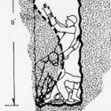
I'm putting a light fixture in my ceiling, except I live in a condo so there's not really wood rafters in the traditional sense. I shoved my phone up there and took a picture. I have these metal deals going along. I bought a Safe-T-Bar brace, where the ends secure themselves into the wood. Would that work with this metal stuff that is up there?
|
|
#
?
Dec 3, 2011 23:19
|
|

|

|
| # ? May 9, 2024 05:29 |
|
|
FogHelmut posted:I shoved my phone up there and took a picture. I have these metal deals going along. I bought a Safe-T-Bar brace, where the ends secure themselves into the wood. Would that work with this metal stuff that is up there? Here's what a typical truss plate joint looks like:  And no, there's no issue using a spreader with one, so long as it bites into the wood; you should feel it grab as you set it. grover fucked around with this message at 03:44 on Dec 4, 2011 |
|
#
?
Dec 4, 2011 03:41
|
|