


|
ANIME AKBAR posted:Yeah, that's more like it. 80MHz, and the DMA controllers do look better (but only four channels is sort of a bummer).
|
 #
?
Feb 13, 2012 20:46
#
?
Feb 13, 2012 20:46
|
|
 ), and use one SPI port just for an SD card and use that for fast storage.
|

|
| # ? May 21, 2024 15:43 |
|
|
Can somebody explain wall warts to me? I just switched my network around a bit, and realized I've been running my main router for about a year on a 12v power supply when the router says it needs 5v. Router always ran a bit hot, but was rock stable. Why did this work and not destroy my router?
|
|
#
?
Feb 13, 2012 23:34
|
|
|
Triikan posted:Can somebody explain wall warts to me? I just switched my network around a bit, and realized I've been running my main router for about a year on a 12v power supply when the router says it needs 5v. Router always ran a bit hot, but was rock stable. Why did this work and not destroy my router? I'm guessing the router has it's own built in voltage regulator, which was probably getting taxed pretty hard if that's the case.
|
|
#
?
Feb 14, 2012 01:04
|
|


|
Triikan posted:Can somebody explain wall warts to me? I just switched my network around a bit, and realized I've been running my main router for about a year on a 12v power supply when the router says it needs 5v. Router always ran a bit hot, but was rock stable. Why did this work and not destroy my router? As mentioned above, but in a bit more detail: The first device inside your router's power chain is probably a simple linear voltage regulator. More or less, this takes "whatever comes in on the input", gives X volts on the output (5 for a 7805 for example), and gets rid of the difference as heat. So, say your router truly runs off 5 volts and your wart was putting out 6 (this is common, warts usually sit a few volts high). If your router was drawing one amp of current, the voltage regulator would have to get rid of ((6 - 5) * 1) = 1 watt of power. If, however, your wall wart was giving off 14V (about average for 12V warts), that same chip had to dissipate (14 - 5) * 1) = 9 watts of heat, much much higher. Many devices are starting to use switching regulators however, which can convert power more efficiently into a desired voltage/current and do not just shunt off the excess as thermal energy.
|
|
#
?
Feb 14, 2012 09:54
|
|


|
Jonny 290 posted:Many devices are starting to use switching regulators however, which can convert power more efficiently into a desired voltage/current and do not just shunt off the excess as thermal energy. 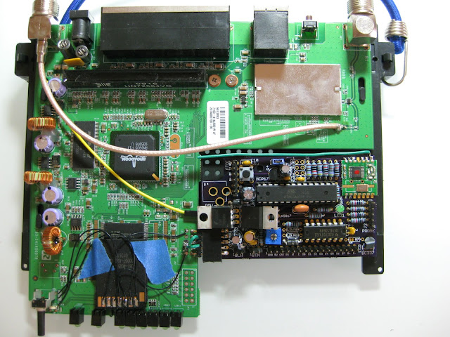 Along the left side you the see 3 large inductors, each of these is connected to a separate buck converter. A buck converter being a switching step down DC-DC converter. The converters themselves are the little 8 pin deals next to each inductor. There are 3 different voltages being generated here, 5V, 3.3V and (iirc) 1.8V. If you look at the board I've added it has a 7805 linear regulator on it to generate 5V from the 12V input. I only pull a max of 35mA so it isn't too wasteful to use the linear regulator. Switching regulators can be pretty efficient 80-90% so as I understand it they can take 12V 1Amax and turn that into say 5V 1.92Amax (assuming 80% efficiency). Switching regulators can also generally take higher input voltage, because they don't generate as much waste heat.
|
|
#
?
Feb 14, 2012 19:21
|
|

|
CapnBry posted:If you look at the board I've added it has a 7805 linear regulator on it to generate 5V from the 12V input. I only pull a max of 35mA so it isn't too wasteful to use the linear regulator. Woah, what the hell did you do to that router? What're you using the arduino for? 
CrazyLittle fucked around with this message at 21:18 on Feb 14, 2012 |
|
#
?
Feb 14, 2012 21:13
|
|


|
I'm chugging along and trying to keep newbie questions to a minimum. Can someone tell me about servos vs. steppers?
|
|
#
?
Feb 14, 2012 22:09
|
|

|
Yes! Lets first clarify. A servo is any actuatator with a feedback device. Most electric motors, when you apply power, they keep turning. this means if you apply power to an electric motor, you don't know how far it's gone. Stepper motors are a kind of electric motor with good holding torque, and when fed the correct power pattern, will step one fraction of a turn per pulse. The steps vary, but most are .6 or 1.6 degrees. They have some standard sizes, for instance nema 17 and nema 23. The advantage of stepper motors, is you can drive them blind. If you "assume" the steps happen, you can blindly drive a stepper motor and "guess" where it is. So, what if you really want to know where your stepper motor is? There are ways of doing that. it's called an encoder. Adding an encoder, (or sender) you can figure out where the the motor is. This is the essence of a servo. A servo is a motor, with feedback. Now, with feedback, you can stop assuming where your motor is. That means you can use those unreliable, "just keeps spinning" motors to drive things in a precise manner. The feedback rule, also applies to all sorts of devices. There are hydraulic servos, servos that feedback based on rpm, acceleration, all sorts of systems. The essential part that makes a servo, a servo, is that feedback mechanism.
|
|
#
?
Feb 14, 2012 22:21
|
|

|
Fooley posted:I'm chugging along and trying to keep newbie questions to a minimum. Can someone tell me about servos vs. steppers? A servo is any motor where there's feedback to the logic. A sensor of some sort can determine the position of the motor. Your application says "move to X" and the controller drives the motor towards X until the sensor says it's at X. A stepper is a specially-wound DC motor with two (typically) coils. Energizing the coils in sequence causes the shaft to spin in a certain direction, with a certain known distance. If you energize the coils A+ B+ A- B-, then the motor will step four steps in the + direction. If you know your motor is 1.8degrees/step, then it just moved 7.2 degrees. If you energize the coils B+ A+ B- A-, 7.2 degrees in the - direction. Most controllers pay attention to current, and can partially energize two coils at the same time, and give you smaller microsteps, so one "step" you ask the controller to perform is acutally 1/2 (or 1/8 or 1/16) of a physical step. This all works out great as long as the needed force is less than the holding or moving force of the stepper. Once you need to move something above that force, the controller will keep sending steps, expecting the shaft to move, but it doesn't. Steppers can have feedback on them and become servos. Edit: Yay! We said the same thing!
|
|
#
?
Feb 14, 2012 22:21
|
|


|
Thanks. That's a lot more concise than what I was finding elsewhere. I'm sort of combining learning electronics with another project I've been wanting to do, and my platform is going to be an old Power Wheel (which I was just going to make RC). Now, am I right in geussing a servo would be better for steering, so that when it gets jostled It'll be easier to correct? Like, X turns it a certain angle, it hits a bump, the servo sends back X+1, I can tell it to go back to X?
|
|
#
?
Feb 14, 2012 22:39
|
|
|
Fooley posted:Thanks. That's a lot more concise than what I was finding elsewhere. I'm sort of combining learning electronics with another project I've been wanting to do, and my platform is going to be an old Power Wheel (which I was just going to make RC). Now, am I right in geussing a servo would be better for steering, so that when it gets jostled It'll be easier to correct? Like, X turns it a certain angle, it hits a bump, the servo sends back X+1, I can tell it to go back to X? Most servos hold position. SO you say "go to X" and it constantly drives to X, bumps and turns and whatnot included. Most R/C stuff is servos.
|
|
#
?
Feb 14, 2012 22:54
|
|
|
Does anyone know where I can get cheap (<$10) pressure, weight, or liquid level sensors? I also want some thermocouples if possible. I'm trying to build a model continuous reactor system for a chemical engineering course. Everything will be hooked up to an atmega168's ADC.
|
|
#
?
Feb 15, 2012 04:46
|
|
|
babyeatingpsychopath posted:Edit: Yay! We said the same thing! Will Rice posted:Does anyone know where I can get cheap (<$10) pressure, weight, or liquid level sensors? I also want some thermocouples if possible. I'm trying to build a model continuous reactor system for a chemical engineering course. Everything will be hooked up to an atmega168's ADC. The jerk answer is "yes." But I don't think that's what you're looking for. Off the top of my head, I can think of mechanisms that would work for all of your needs, but we'd need to know more about weights, volumes, working materials, and temperatures to get specific. A cheap way to measure weight, is to pick a LONG spring, and hang your weighed item from it. Use a linkage to drive a potentiometer, and you have a cheap, reasonably accurate, scale. You'll need to calibrate it to be useful for your range of weights. Or you can buy a load cell. Floats, can do the same thing for a liquid's level. Exactly the same way. Your sump pump in the basement likely has a float hooked to a switch. If you just need "absolute" levels, well there's a good use for a $0.50 microswitch and $3 in foam/wire. You could also use a pressure sensor and a dip tube. Or you can buy a capacitive fluid level sensor. Temperature, for "normal" temps, can be handled by thermistors. If the temps are much higher than say... boiling, you'll need the pot + linkage method to help you, a bi-metal strip and a linkage will do about the same thing and work right up to the melting point of the metals. Or you can buy a instrument amplifier and the proper range thermocouple.
|
|
#
?
Feb 15, 2012 05:07
|
|
|
Nerobro posted:The jerk answer is "yes." Most educational reactors use aqueous solutions (or perhaps organic) operating between 50-75 C. I've been debating whether to use an indirect (via pressure or weight) or direct method of measuring liquid level. It sounds simple enough to the liquid level sensor, so I'll probably go with that. For temperature sensing, it is important that the sensor be in good thermal contact with the solution and resistant to corrosion.
|
|
#
?
Feb 15, 2012 05:46
|
|
|
Will Rice posted:Does anyone know where I can get cheap (<$10) pressure, weight, or liquid level sensors? I also want some thermocouples if possible. I'm trying to build a model continuous reactor system for a chemical engineering course. Everything will be hooked up to an atmega168's ADC. Ebay has some cheap thermocouples (type K was the one I was after) for $1-2 each with free shipping. I'm using a few in an arduino-based datalogger (using the MAX6675 to read the thermocouple).
|
|
#
?
Feb 15, 2012 10:47
|
|

|
I'm designing a temperature-controller system for my soldering station since the original (Ersa custom) IC seems to have died. I've figured out the heating element in the soldering iron acts as a thermistor, and have designed an exponential function that fits pretty well with my measurements (bolting a thermocouple to the tip, heating it up and then logging resistance vs. temperature as it decreases). My drive system will be a low-side switching mosfet (IRF1407), and I've put together a driver that will ensure fast switching (hope to avoid heatsinking it). But how do I measure resistance while it's powered up?  This is the current design, ignore the exact resistor values, they are definitely temporary. What I'm thinking is I'll force the driver to conduct, and measure the voltage across a 0.1 ohm resistor connected between the source of the drive transistor and ground, which will give a measurement of current without excessive heat dissipation (and possibly use a lower voltage as the analog reference to improve resolution?). The input voltage will not be regulated so to avoid errors I'm thinking I should put together a voltage divider and use that to measure the (~30VDC) input voltage. Then I'll have a measurement for current (voltage across 0.1R to ground), and assuming the mosfet is a short I'll know the voltage across the soldering iron? The prototype will be an Arduino to test the concept, but I'll be using something in the PIC16 range for the final design.
|
|
#
?
Feb 15, 2012 16:55
|
|


|
longview posted:I'm designing a temperature-controller system for my soldering station since the original (Ersa custom) IC seems to have died. You could just measure the voltage at the drain of the MOSFET. That seems the most obvious way to tell the voltage across your load. But if your Rdson is small enough, and your currents are low enough, you could get away with assuming it's 0. Or make your current measurement on the drain side of the MOSFET - if you can assume it's 0 when on, then it shouldn't affect the current measurement (much). You also probably want to use a smaller current sense resistor - at 50W, if your iron is a 10 ohm load, you will be burning ~0.5W in your resistor. This is not necessarily true if you decide to change the current measurement to use the FET drain. I'd also add a pull up on Q3, or switch to an integrated FET driver.
|
|
#
?
Feb 15, 2012 17:23
|
|

|
CrazyLittle posted:Woah, what the hell did you do to that router? What're you using the arduino for?  It used to have a ZeroG SPI wireless on it, but turns out you can't do a whole lot of dynamic web content on a 16MHz CPU with 2K of RAM and 32K of storage. The SD card is for additional database storage, and the green chip on my board is for 915MHz RF probes. I'm really looking forward to the RaspberryPi coming out so I can squeeze all this into a much smaller, much awesomer package for less cost.
|
|
#
?
Feb 15, 2012 18:17
|
|
|
longview posted:What I'm thinking is I'll force the driver to conduct, and measure the voltage across a 0.1 ohm resistor connected between the source of the drive transistor and ground, which will give a measurement of current without excessive heat dissipation (and possibly use a lower voltage as the analog reference to improve resolution?). Instead of using a lower reference, maybe a cheapo 3-terminal current monitor is in order. This will let you scale up your current measurement easily. I'm not sure you need to sense voltage. In an unregulated supply, the output voltage will depend directly on the output current, so fitting temperature vs. current should be adequate. This doesn't compensate for bad ripple, but that shouldn't be an issue in a system this slow.
|
|
#
?
Feb 15, 2012 19:34
|
|
|
kXGh43KbAuYgjOok1u4s WncLcx3G61uJfnOi6n2N lfNkkvXh3BBJmHLsglQh j9Fsx7Z8szyk1FqNxWco 6rG6fOUbxuYREaNr4aIt rFMkeXUdJjr1WuSD3BGm 8b42PER6XrrK1DyibyvQ EjSO5531X7ZlGAmm1LSa J7dk6Yxe34YBf8ree2XK jPWlT5OhN6kJpurIRBGV Plasmafountain fucked around with this message at 21:13 on Feb 28, 2023 |
|
#
?
Feb 16, 2012 13:30
|
|

|
"APRS" is a way of transmitting short data packets over radio, and is used particularly well with GPS. http://aprs.fi/ is a good example of people using the system already (integrated with google maps API) https://www.adafruit.com/blog/2011/07/10/trackuino-an-arduino-aprs-tracker/ is an arduino-friendly transmission board someone's made up. Your radio transmitter will have to be suited to your local radio spectrum laws. I don't know the deep mechanics of how the system works or if you need any radio licenses etc. to use it (probably do). These links are a good starting point anyway... Edit: reading up on this; the system relies on people volunteering their radio equipment to act as a repeater or a link from radio network to internet network. I'd be very mindful of respecting the system by not blasting out data willy-nilly. SandBox fucked around with this message at 15:59 on Feb 16, 2012 |
|
#
?
Feb 16, 2012 15:53
|
|

|
You could look into a Bluetooth shield if you're going the Arduino route. I don't know about personal Bluetooth, I've been using a commercial Bluetooth module for work that boasts a 1000 metre range
|
|
#
?
Feb 16, 2012 16:33
|
|

|
ante posted:You could look into a Bluetooth shield if you're going the Arduino route. I don't know about personal Bluetooth, I've been using a commercial Bluetooth module for work that boasts a 1000 metre range Usually these balloons are working in the 60-150,000foot range, not the 9000' range.
|
|
#
?
Feb 16, 2012 16:46
|
|
|
ante posted:You could look into a Bluetooth shield if you're going the Arduino route. I don't know about personal Bluetooth, I've been using a commercial Bluetooth module for work that boasts a 1000 metre range Ha! Anyways, the my Uni does high altitude balloon stuff semi-regularly, and they keep losing the drat things. I don't have much to add, but I want to warn you that you probably have the hardest job. Getting them to go up is relatively trivial; finding them when they come down is a bitch-and-a-half. Look into HAM equipment, it's your best bet for getting the necessary range.
|
|
#
?
Feb 16, 2012 19:26
|
|

|
Hello! Another question (sorry - hopefully one day I'll be able to give back..). I'm trying to power a board with an input voltage range of 19-30V with an 11.1V 3cell battery. My options are really: 1. Use a 6 cell battery, and do some nifty wiring so that the brushless motor speed controllers also on the circuit see 11.1V. This *could* cause weird discharging (I'm a little scared of LiPoly batteries as it is...). 2. Find a DC-DC boost converter that can do what I want. I've got to etch a PCB for this project anyway, so adding a few components isn't too much of a drain. My initial googling reveals something like the LM2731 as a potential candidate. I'd need to do some calculations, but my understanding is that with some nifty resistor combinations I could get that chip to output 20V or so. Is there any easier option on the DC-DC side? Someone was talking about the Murata Oki earlier - a step-up converter with that sort of convenience would be fantastic! Is that a wish too far? Any help would be very much appreciated! Edit: Zero Gravitas posted:Ive seen other peoples projects where they use a gprs module to send a text with data but i feel im out of my depth there since the simplest version ive found involves programming languages im not familiar with and involves interpreting between the device and arduino. This guide for the use of this GPRS shield seems fairly simple. You'd have to figure out the AT command set, but that's a fairly standard serial interface thing that you'll probably have to do with almost any solution you find. The example code really is fairly simple: code:leo_r fucked around with this message at 19:39 on Feb 16, 2012 |
|
#
?
Feb 16, 2012 19:32
|
|
|
Finding a lost balloon is easy if you're in a populated area: just attach a note with a phone number and a notice of a $50 reward for returning the balloon and its equipment. ")
|
|
#
?
Feb 16, 2012 19:38
|
|


|
Check out this incredible craftsmanship I just found in the goon project thread, y'all:thehoj posted:I built a custom 9-watt guitar tube amp.
|
|
#
?
Feb 17, 2012 16:22
|
|


|
Not too fond of that rat's nest-like construction, but it's really very nice despite that. I guess he should probably insulate some of those exposed leads, though.
|
|
#
?
Feb 17, 2012 19:15
|
|
|
Isn't there some sort of linear correlation between the awesomeness of an amp relative to the likelihood of fatally electrocuting oneself during its normal use and operation? I think that's, like, Newton's 11th.
|
|
#
?
Feb 17, 2012 19:16
|
|
|
Every tube amp I've taken apart looks like that on the inside, regardless of the 'professionalism' of the manufacture. I'm not sure what you gain by stringing the parts all willy nilly like that, but it seems to be The Way It Is Done.
|
|
#
?
Feb 18, 2012 00:34
|
|
|
This SHOULD be the last beginner question. Say I want to use this circuit to power a stronger motor: I would need a MOSFET and diode rated for higher continuous voltage and current, right? Eventually I'm going to want to reverse the direction of the motor too, so I'd need a relay that's rated for what I'm doing?
|
|
#
?
Feb 18, 2012 05:30
|
|
|
Delta-Wye posted:Every tube amp I've taken apart looks like that on the inside, regardless of the 'professionalism' of the manufacture. I'm not sure what you gain by stringing the parts all willy nilly like that, but it seems to be The Way It Is Done. I think that is more the way it used to be done, and tube amps just happen to be from that era. As far as I know there is no advantage besides not having to produce/buy a PWB. The exposed AC plus metal enclosure seems dangerous to me.
|
|
#
?
Feb 18, 2012 06:55
|
|


|
Eh, just keep an 0.5A fast-blow in line with the AC and keep a hand in your pocket when twiddling. You guys would back away slowly from the '53 Silvertone two-tube combo under my bench. All of the cloth wiring's insulation is mostly gone inside. Bare wires errywhere (assuming ~250V for the plates, haven't ever metered this amp out to be honest). Still works, too, with the exception of a bypassed volume control. I have no idea how those caps have not shorted. 6K6's are a weird choice, for sure. Jonny 290 fucked around with this message at 09:12 on Feb 18, 2012 |
|
#
?
Feb 18, 2012 09:09
|
|
|
I have a EL6400 PA amp stashed away somewhere, EL81 based, one time it snowed in the window and DRENCHED it in water (plugged in, turned off), after spraying rubbing alcohol all over it worked fine. Internal construction looked exactly like that picture too.
|
|
#
?
Feb 18, 2012 11:07
|
|
|
OK, long explanation, short question. I was looking at connecting an rfid reader, camera(usb), wireless card, and arduino for a while. Stacking shields, using adapters, lots of terrible fun. It kind of dawned on me that it would be easier and cheaper to find a tiny pc that I could run linux on to pretty much take care of the whole thing... It's important I have wireless networking, 1 usb port, 1 uart, not a real tall order. My real problem is most of the systems I am finding overshoot my needs pretty bad, and power consumption is an issue. My search method has just been googling, but there is just way too much out there. Some of the most promising things I've found have been hacked home NAS devices from linksys. So the question is, is there a go to source for this sort of thing? browsing through these random manufacturers is a real beating.
|
|
#
?
Feb 18, 2012 20:43
|
|


|
81KK6e6g3buD4rIu3mOn PW327x12kEuQC8yz9bAh aAFkSl8TZgyo3E6Ynqpe v9Wq0KdgYhClvp6xbmS9 ZZoeTV5LgkCmKdnOiEgH 8eLr7qAel7YxNLXNPnHu vgVgIkuIjchpdzukSZSb yQqkGNxtm8yCkumzKyqo TV3BdO5JUWpdXanrPAQS 6m23ZNmjETHaCDLRUMdH Plasmafountain fucked around with this message at 21:13 on Feb 28, 2023 |
|
#
?
Feb 19, 2012 01:43
|
|
|
As long as the pins have the same functions available to them, you can change D2 in code to whatever you want. If you need even more pins, look up how to use shift registers for IO expansion. Looks like you should have enough if that's all you're using, though.
|
|
#
?
Feb 19, 2012 02:06
|
|
|
If you're really planning on using the arduino, here I am once again to pimp the teensyduino. It's better in pretty much every way, and is arduino-compatible, so the same code and libraries and such will work just fine. You even develop for it using the arduino environment. I'll just quote myself here: Bad Munki posted:So I finally got around to trying out a teensyduino. My broad stroked trip report is that as a replacement to the standard arduino, it is better in just about every way.
|
|
#
?
Feb 19, 2012 02:09
|
|
|
Planning on building a little switch that switches between my PC speakers and headset and came across this little gem. Wondering what type of switches I should be getting (looks like there's two there) at the radioshack. DPDT? No idea  I also don't need the ext mic port (just the one mic) so I guess I'm just switching between the headset and main speakers. Tried searching for "3 pole 2 position switch" and didn't really find anything useful on the google. I also don't need the ext mic port (just the one mic) so I guess I'm just switching between the headset and main speakers. Tried searching for "3 pole 2 position switch" and didn't really find anything useful on the google.
|
|
#
?
Feb 20, 2012 19:32
|
|


|

|
| # ? May 21, 2024 15:43 |
|
|
You should probably give everything a common ground so that you only need a double throw switch.
|
|
#
?
Feb 20, 2012 20:03
|
|