


|
Anyone have experience with the Microchip CAN demo board(s) with 18F4550 microcontroller and MCP2515/2551 CAN controller/transceiver? Digikey: http://www.digikey.com/product-detail/en/MCP2515DM-BM/MCP2515DM-BM-ND/1999510
|
 #
?
Jul 8, 2013 04:40
#
?
Jul 8, 2013 04:40
|
|


|

|
| # ? May 8, 2024 11:19 |
|
|
Got my boards back from Seeed finally. Man, some of these traces are reeeeally cutting it close. I didn't account for the silvering of the through-holes so I've literally got like a hair's break between a hole and a trace. They were e-tested so I'm not sure if that means there's currently no leakage, but since it's just two traces I might razor blade them and run a jumper wire just to be safe. I'll file this one away under "lessons learned". I'll have to go back to the Eagle layout and see how it looks so I know what to expect next time.  Not sure why the heck I routed pin4 between 1 and 2 instead of out and around them  -- that just seems like a weirdo autorouter decision that I didn't catch. -- that just seems like a weirdo autorouter decision that I didn't catch.
|
|
#
?
Jul 8, 2013 20:01
|
|


|
So I'm looking for a simple MCU with USB support for a little project; the USB part is literally as simple as getting a command from the computer to trigger LEDs on/off. Essentially right now the project uses some webcam where you have to solder to the VSync output to use that as a clock to trigger the IR LEDs on/off; I figure that I can hack up their openFramework-based PC app to talk to libusb and trigger every frame as well. I'm most used to PICs and own the devtools there, has anyone used a PIC with the hardware USB mode yet? I don't want to touch AVRs and V-USB again, especially because of the electrical compromises you have to make and because I've had poo poo luck with them. Any other vendors to be looking at / simpler solutions I've missed?
|
|
#
?
Jul 8, 2013 21:36
|
|

|
movax posted:So I'm looking for a simple MCU with USB support for a little project; the USB part is literally as simple as getting a command from the computer to trigger LEDs on/off. Essentially right now the project uses some webcam where you have to solder to the VSync output to use that as a clock to trigger the IR LEDs on/off; I figure that I can hack up their openFramework-based PC app to talk to libusb and trigger every frame as well. Every time I've wanted USB on a board I've gone with an FTDI USB to serial converter. I think they're a couple bucks and it should be easier on both the PC and the Micro side. Actually you don't even need a micro, you can control outputs of the FTDI directly via USB if that's truly all you need. If you go with a USB micro just make sure you understand the software/driver landscape first. That's where any and all difficulty will arise.
|
|
#
?
Jul 8, 2013 22:44
|
|

|
Seconding the FTDI chip, if you want to go from USB to gpio/whatever it's definitely the way to go. We use one to go from USB to AXI on an FPGA and it works great.
|
|
#
?
Jul 8, 2013 22:48
|
|

|
Martytoof posted:that just seems like a weirdo autorouter decision that I didn't catch. Is there any other sort of autorouter decision?  I'm looking at that little picture and it seems much more complicated than needed. I'm looking at that little picture and it seems much more complicated than needed.
|
|
#
?
Jul 8, 2013 22:52
|
|

|
priznat posted:Seconding the FTDI chip, if you want to go from USB to gpio/whatever it's definitely the way to go. We use one to go from USB to AXI on an FPGA and it works great. One of the side benefits to the FTDI is that if you only need a few additional io then you can just use the hardware flow control lines, which is great if you just want to use the generic driver, or if you already have one for the serial port and want to trivially add an I/O or two for controlling reset or whatever (or power, if you don't want to use the pin it has for shutting off a peripheral device if the bus goes inactive).
|
|
#
?
Jul 8, 2013 22:57
|
|
|
Delta-Wye posted:Is there any other sort of autorouter decision? Eh, kind of. The weird route-poo poo-between-pins could have been fixed somewhat with some vias. This particular board is just a 1:1 10-pin passthrough. There are two 5x2 headers on the board, one on each side of the board, only the header on one side is flipped and upside down to better match a cable that attaches to it. It's kind of dumb but hopefully it works well ")
some kinda jackal fucked around with this message at 23:01 on Jul 8, 2013 |
|
#
?
Jul 8, 2013 22:57
|
|
|
Martytoof posted:Eh, kind of. The weird rouge-poo poo-between-pins could have been fixed somewhat with some vias. This particular board is just a 1:1 10-pin passthrough. There are two 5x2 headers on the board, one on each side of the board, only the header on one side is flipped and upside down to better match a cable that attaches to it. It's kind of dumb but hopefully it works well Just stick a ohmmeter on those two signals to verify leakage, and if that's good you should be ok unless you need more voltage isolation, or if capacitive coupling could be a problem.
|
|
#
?
Jul 8, 2013 23:00
|
|
|
Good idea. It's just a pet project so if I wasted $15 I'm not too stressed over it, but hopefully they'll work as is.
|
|
#
?
Jul 8, 2013 23:02
|
|
|
Also don't use the autorouter unless you have $4000 packages with an autorouter made of solid gold designed by the gods or something. For simple designs, you'll find doing everything by hand can be really quick, result in a much cleaner board, and be very satisfying. You get good at it pretty quickly.
|
|
#
?
Jul 9, 2013 03:55
|
|

|
Yeah, lesson learned I've already got a second board ready and it's definitely going to be hand-routed.
|
|
#
?
Jul 9, 2013 03:57
|
|
|
Even with the top end Cadence Allegro tools it's still pretty necessary to go in and just massage things by hand. Basically let it do its thing which would normally take up a lot of time then go in and clean it up  Did the layout tool not have some DRC that you can set keepouts around pins/vias/traces? Something to enable in the future.
|
|
#
?
Jul 9, 2013 04:10
|
|
|
Can someone explain to me how it is that these two LEDs can apparently have all the same specs (forward voltage, max current, suggested current) but have such hugely varying brightness (200mcd vs. 10,000mcd)? I feel like I must be missing something critical and obvious about them. But they both say their suggested operating current is 16-18mA, so that means on, say, a 60mAh battery, they'd both last about 3 hours, right? But one would be 50 times brighter? 200mcd: https://www.sparkfun.com/products/9594 10,000mcd: https://www.sparkfun.com/products/530
|
|
#
?
Jul 9, 2013 04:38
|
|


|
Bad Munki posted:Can someone explain to me how it is that these two LEDs can apparently have all the same specs (forward voltage, max current, suggested current) but have such hugely varying brightness (200mcd vs. 10,000mcd)? I feel like I must be missing something critical and obvious about them. But they both say their suggested operating current is 16-18mA, so that means on, say, a 60mAh battery, they'd both last about 3 hours, right? But one would be 50 times brighter? mcd measures brightness at a point, not total light output. One has a very narrow beam, 10 degrees or less, and the other has a beam of between 40 and 60 degrees (measured at 50% brightness). The total amount of light is approximately the same, but the brightest point is much brighter with a narrow beam.
|
|
#
?
Jul 9, 2013 04:49
|
|


|
Ah, there we go, thanks.
|
|
#
?
Jul 9, 2013 04:51
|
|
|
asdf32 posted:Every time I've wanted USB on a board I've gone with an FTDI USB to serial converter. I think they're a couple bucks and it should be easier on both the PC and the Micro side. Actually you don't even need a micro, you can control outputs of the FTDI directly via USB if that's truly all you need. priznat posted:Seconding the FTDI chip, if you want to go from USB to gpio/whatever it's definitely the way to go. We use one to go from USB to AXI on an FPGA and it works great. Slanderer posted:One of the side benefits to the FTDI is that if you only need a few additional io then you can just use the hardware flow control lines, which is great if you just want to use the generic driver, or if you already have one for the serial port and want to trivially add an I/O or two for controlling reset or whatever (or power, if you don't want to use the pin it has for shutting off a peripheral device if the bus goes inactive). Hmm, didn't think of that, thanks! The only problem with committing to the FTDI route is that if it doesn't end up working, I don't have the capability of doing it the "old" way with the VSync. Basically I'm helping out some grad students with an implementation of this and replacing the clunky-rear end Arduino with a tiny dedicated circuit / PCB. With a regular micro, I can either do the same thing the Arduino is doing or try the USB approach on the same board super easily, just with a few strategically placed 0 ohm resistors. Going the FTDI route I think limits my options when it comes to doing it the "old" Arduino way, though that sketch makes me feel like I could do the same thing with a transistor and op-amp.
|
|
#
?
Jul 9, 2013 06:12
|
|
|
Also I do want to find a better spot for this kind of post in the upcoming future, but seeing as most EEs/CEs check by this thread, if you're interested in work in MI, let me know. I need to find a replacement for myself  FPGA, circuit / PCB design, BIOS development, kernel development, etc. The FPGA knowledge is probably the primary thing to know, everything else is icing on the cake / things you will be expected to pick-up. FPGA, circuit / PCB design, BIOS development, kernel development, etc. The FPGA knowledge is probably the primary thing to know, everything else is icing on the cake / things you will be expected to pick-up.
|
|
#
?
Jul 9, 2013 07:04
|
|
|
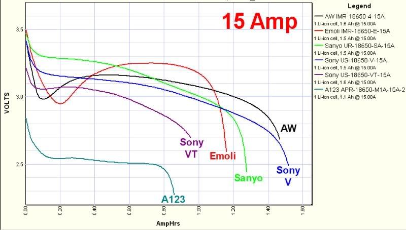 Can anyone explain why a battery voltage would dip very low initally and then come back up? Is this solely from the battery warming up and lowering its own internal resistance?
|
|
#
?
Jul 12, 2013 10:35
|
|


|
The discharge curves for the Sony V and Sanyo under that load look more like the normal discharge curve for an alkaline than a Li-ion 
|
|
#
?
Jul 12, 2013 15:17
|
|

|
After a zillion distractions, I finally got that valve installed in my truck today. I'd like to thank everyone helping me figure out that race condition with my relays. Come by St. Louis sometime and I owe you a beer.
|
|
#
?
Jul 13, 2013 00:13
|
|
|
peepsalot posted:
If those were lead-acid cells, I'd say surface charge, but Li-ion is magic. Like how they get constant current charge to one point, then constant voltage charge; maybe the electronics discharge the cells the same way.
|
|
#
?
Jul 13, 2013 00:26
|
|


|
My multimeter, which is only about 7 months old, has suddenly decided that every voltage difference is 0.00V. I turn it on, it starts at about ~50mV, and then quickly drops to 0.0, no matter what I try to measure. It's obviously busted, but I tried switching batteries and that didn't help. None of the modes work, I tried diode, continuity, current, V, mV... This is an Extech True RMS 430. Any ideas? Any options for me to fix it? I've got the cords plugged in to the right terminals. It sometimes gives me an error light implying the cords aren't connected, but they're wedged in there as well as I can get them and I think if the cords weren't connected, it would still display a nonzero voltage difference across those terminals.
|
|
#
?
Jul 13, 2013 00:39
|
|

|
I was going to say that your battery is dead, because that sounds exactly like what happens to cheap multimeters when they have dead batteries. Not that the Extech is cheap -- I have a 330 and it's excellent -- but I've only ever seen that mystery failure mode with cheap ones because the expensive ones have a low battery warning indicator that comes on before they start to screw up. Are you sure the batteries are good? If that's not it, did you do something kinda dumb like try to measure a high voltage when you were in current mode? Some of the modes connect the meter's probes to a huge internal resistor and some have effectively no resistance, so it is certainly possible to burn the meter out if you hook it up the wrong way in certain modes. Also check the internal fuse. If it's blown, replacing it may or may not fix it, but at least it'll tell you that you did a no-no at some point.
|
|
#
?
Jul 13, 2013 01:23
|
|


|
Sagebrush posted:I was going to say that your battery is dead, because that sounds exactly like what happens to cheap multimeters when they have dead batteries. Not that the Extech is cheap -- I have a 330 and it's excellent -- but I've only ever seen that mystery failure mode with cheap ones because the expensive ones have a low battery warning indicator that comes on before they start to screw up. Are you sure the batteries are good? I vote you go buy a new multimeter so you'll have a tool to measure the broken meter's batteries 
|
|
#
?
Jul 13, 2013 01:55
|
|
|
Those plots for the Li-Ion cells are during a 15A discharge, right? Probably some serious heating going on when you discharge a battery in 6 minutes.
|
|
#
?
Jul 13, 2013 03:23
|
|

|
Kire posted:My multimeter, which is only about 7 months old, has suddenly decided that every voltage difference is 0.00V. I turn it on, it starts at about ~50mV, and then quickly drops to 0.0, no matter what I try to measure. It's obviously busted, but I tried switching batteries and that didn't help. None of the modes work, I tried diode, continuity, current, V, mV... I bet you have a broken lead. Check continuity of one lead, then the other. Just plug one lead in, and test it against the opposite socket.
|
|
#
?
Jul 14, 2013 02:40
|
|
|
So, I've been trying to come up with a decent anemometer, since that is the only sensor that isn't easily available to connect to an Arduino or whatever. I've come across various options, but most recently I came into possession of a car stereo that had a rotary volume controller that I think MIGHT work...it's an ALPS rotary switch, but I have no information about the pinout. It has two pins on one side, and three pins on the other. My goal is to use this as a rotary encoder for measuring wind speed...any suggestions?
|
|
#
?
Jul 14, 2013 05:11
|
|

|
I think the usual way of building an anemometer is with a small DC motor with the little paddles on it. Build a voltage divider to get the value down to the 0-5v the Arduino can handle, and don't forget the diodes.
|
|
#
?
Jul 14, 2013 05:22
|
|
|
Little paddles + shaft to put the little paddles on + a magnet + a hall effect sensor + one of the pins on your arduino. there are a bunch of ways to skin this particular cat.
|
|
#
?
Jul 15, 2013 01:29
|
|
|
babyeatingpsychopath posted:I bet you have a broken lead. Check continuity of one lead, then the other. Just plug one lead in, and test it against the opposite socket. I did that, and discovered that the inside of the COM socket had some grime built up that I hadn't noticed. Cleaning that out fixed it, thanks!
|
|
#
?
Jul 17, 2013 00:15
|
|
|
Sagebrush posted:I think the usual way of building an anemometer is with a small DC motor with the little paddles on it. Build a voltage divider to get the value down to the 0-5v the Arduino can handle, and don't forget the diodes. This is pretty slick, but unless you can generate windspeed to voltage calibration tables I think an opto-interruptor or anything else that can give you pulses will be much simpler. A DC motor will probably brake the anemometer as well.
|
|
#
?
Jul 17, 2013 00:58
|
|
|
How does a pulse based solution obviate the need for calibration? Is it really too hard to get a fan and another meter?
|
|
#
?
Jul 17, 2013 01:03
|
|

|
Well, you get an actual RPM measurement. If you already know your anemometer's characteristics it's good enough. If you don't, you still have to find a halfway decent windspeed reference.
|
|
#
?
Jul 17, 2013 01:10
|
|
|
sixide posted:Well, you get an actual RPM measurement. If you already know your anemometer's characteristics it's good enough. If you don't, you still have to find a halfway decent windspeed reference. Wouldn't you still need an RPM->mph conversion function? Otherwise, RPM seems roughly equal to voltage in information content 
|
|
#
?
Jul 17, 2013 05:13
|
|
|
You can use RPM without factoring in the size or efficiency of the fan?
|
|
#
?
Jul 17, 2013 05:53
|
|

|
The PSU on this computer sucks. If I try using something GPU intensive, or even a few minutes after I've stopped for some reason the computer shuts off yielding an unstable power supply BIOS message. The voltages seem pretty stable. The +12v is slightly suspect but only drifts by maybe 0.2v under load. Here's the weird part. At any time a whack to the desk the computer is on, or even a light tap to the case of the computer causes it to shut off. I'm pretty drat sure it's the PSU and am no stranger to electrics and electronics having designed / built various things including fun things that do things like translate signals and data on the fly, expansion cards etc, and I can do electrics, but the realm of the PSU is slightly out of my area of familiarity. Personally I suspect something like a dry joint for it to be so sensitive to a tap, and to higher load, which still should be well within its rating. Does this sound plausible? what other things should I consider? It just seems a little wasteful to replace something with an intermittent condition.
|
|
#
?
Jul 17, 2013 14:25
|
|
|
General_Failure posted:The PSU on this computer sucks. If I try using something GPU intensive, or even a few minutes after I've stopped for some reason the computer shuts off yielding an unstable power supply BIOS message. I turned the shutdown off, the machine had been grinding on without fault for 2 years now. But I wouldn't dare do that for an expensive computer.
|
|
#
?
Jul 17, 2013 14:39
|
|

|
Delta-Wye posted:Wouldn't you still need an RPM->mph conversion function? Otherwise, RPM seems roughly equal to voltage in information content RPM adjusts linearly, voltage from a motor will not, you will need to calibrate a motor 'sensor' at several points, RPM you can calculate once, and you're done. Also on a negligable load like a magnet/hall sensor the efficiency is a) constant, b) essentially a non-issue in the equation
|
|
#
?
Jul 17, 2013 14:48
|
|
|

|
| # ? May 8, 2024 11:19 |
|
|
Anemometers are not strictly linear (windspeed to rpm), but they are very close. A questionably designed cup anemometer can have <5% error up into severe weather windspeeds. Cup anemometers also are pretty much guaranteed to have a scaling factor between 30 and 50% (speed of cup vs. speed of wind), so you can have a fairly accurate windspeed measurement just by guessing. DC motors can be fairly linear, but they do drop off rapidly at some point. Also, very few motors are designed to handle continuous radial loads (probably the biggest issue).
|
|
#
?
Jul 17, 2013 23:22
|
|