

|
Rescue Toaster posted:Well, the arm-none-eabi toolchain has come a long way in ease of use. I was able to setup Eclipse 4.3, the arm plugin, the toolchain, openocd, and run hello world on my old stm32f4discovery in about 30 minutes (on windows, even). Pretty nice! Did you use any particular instructions to get everything up and running or did you piece it together yourself? I'm kind of off ARM in favour of AVR at the moment, but I'm always looking for fun projects and I've been meaning to get an opensource-ish ARM toolchain/ide combo working again.
|
 #
?
Feb 16, 2014 23:17
#
?
Feb 16, 2014 23:17
|
|


|

|
| # ? May 11, 2024 21:38 |
|
|
Pretty much followed the steps for the GNU ARM Eclipse Plugin http://gnuarmeclipse.livius.net/blog/ And I used the GNU ARM toolchain from launchpad.net. So far the biggest change was I had to add a -f command line option to openocd to use the correct cfg file for the stm32f4discovery board w/ its onboard stlink. Then I was able to debug the 'Hello, World' on the board w/o any actual per-CPU config. (NewLib has a default stdout device that goes to the debug console by magic somehow.) The biggest hurdle now is how to setup configs for different processors (to set ram sizes and such) and how to integrate ST's CMSIS (should have drivers and headers for individual CPUs, I assume). Can't find too much online yet, but it can't be THAT hard if people are using it this much. EDIT: The 'StdPeriph' projects that you can install from the GNU ARM Eclipse Plugin have the CMSIS installed already, though you have to dig through the main header file to make sure you #define everything that needs defining... Rescue Toaster fucked around with this message at 03:41 on Feb 17, 2014 |
|
#
?
Feb 17, 2014 00:12
|
|
|
Delta-Wye posted:Vcc/gnd swap? I've done that with Atmegas before, and they just got slightly warm. After connecting it properly, it still worked fine
|
|
#
?
Feb 17, 2014 18:40
|
|

|
Background: I am using an Atmel SAM4S with a GNU toolchain at work. My predecessor wrote a bootloader despite there being one burned in ROM on this chip. It has a number of legacy constraints that are getting tedious to deal with and causing headaches down the road (bootloader expects certain signatures at offsets in main application firmware, has bugs, industry certifications are issued only for a particular version, etc., etc. A real unnecessary PITA for no real benefit). To completely remove it, I need a way of flashing the main application firmware while the program is running and just use the ROM bootloader when needed. To do this I want to load a reflashing application into RAM and jump to it when we're ready to do an update. So now I have two firmware images, one a custom stripped down reflashing application and one the main program. I'm linking the main application into flash normally and it boots fine. The reflashing app is getting linked to RAM, so I don't think I need to even specify -fPIC if I copy it to where it expects to be run (right?). I can't straight up link them together because many of the sections and symbols have identical names, not to mention I don't want to reserve space in my very limited RAM for this special app I'm executing once in a blue moon. I'd like to have this single contiguous binary blob linked into a section in my main app but don't know the best way to do this as I'm pretty new to binutils. This stackoverflow question looked like what I was looking for: http://stackoverflow.com/questions/17265950/linking-arbitrary-data-using-gcc-arm-toolchain. The only issue is that converting to binary then back to an elf file causes the .ARM.attributes section to be lost and then the linker complains about the CPU architecture when I try to link it into my main application. Basically looking for a way to take a segment from one elf file and jam it all in a section of another. Is there an easy way to do this that I'm missing? It looks like I might be able to prefix the sections and symbols defined in the reflashing app with some string using objcopy and then just add them to my main application linker script avoiding the elf->bin->elf step. Does that make any sense?
|
|
#
?
Feb 18, 2014 06:45
|
|


|
I got it to work by using xxd to generate a .c file for inclusion with my main project. I guess doing this sort of thing without an OS and loader is always going to seem clunky.
|
|
#
?
Feb 19, 2014 03:01
|
|
|
sund posted:I got it to work by using xxd to generate a .c file for inclusion with my main project. I guess doing this sort of thing without an OS and loader is always going to seem clunky. I didn't read your last post, but I had to do something similar. I had to flash some binary, but had to get it into memory first. For me at the time the easiest way was a header, too. I used Bin2h (or something similar)
|
|
#
?
Feb 19, 2014 23:57
|
|

|
Aww yiss, guess who got a J-Link EDU in the mail today. Finally gonna put that LPC800 through its paces!
|
|
#
?
Feb 20, 2014 03:38
|
|
|
The SD shield has arrived, I'm just messing around with the SPI interface at the moment. The card is returning all 1's to every command most of the time, which is odd because the specification says the first byte of the response is always zero. I think I'm misusing one of the lines somehow.
|
|
#
?
Feb 20, 2014 05:11
|
|
|
You could start with the codebase of some existing SD card library. edit: Looking over my old notes now, this was the most useful thing ever for me in 2010ish before reliable SPI SD card libraries were a thing. http://www.esawdust.com/blog/serial/files/SPI_SD_MMC_ATMega128_AVR.html ante fucked around with this message at 08:04 on Feb 20, 2014 |
|
#
?
Feb 20, 2014 07:53
|
|

|
Part of the problem seems to be that the SPI library for arduino is hard coded to CS on pin 10, and my CS is on pin 4. Looks like I'll have to write my own library, which means learning more about how the clock signal works. I assume it needs to be consistently cycling with the rate that the data is sent, and apparently it needs to be between 100 and 400kHz, but does it need to be running all the time, or does the card calibrate itself with those 74 cycles on startup and then only need it when commands are being sent? Does the clock cycle speed actually have to be consistent with time, or does there just have to be a consistent ratio of duty cycle/bits sent throughout all transmissions? I had to get answers, so I grabbed my coat and my trusty .44, and stepped out into the night...
|
|
#
?
Feb 20, 2014 08:47
|
|
|
The slow speed is just because some cards may lose data if they're run faster. You're not transferring large amounts of data so who cares, really. Timing doesn't really matter, if your device has an SPI peripheral, it should pretty much handle that automatically. Give it a byte and it'll clock 8 times at your chosen speed. I hope you're not bitbanging SPI in software, that's a pretty unneeded extra step in complexity. The slave/chip select (CS/SS) pins are inactive(high) when you're not sending data, so there's no special idle timing or anything. From the PM where I sent you some of my relevant code: quote:I notice that you're sending a CMD0 restart before you perform the 74 cycle clock speed loop. I haven't seen that in any of the standards I've read, they've all said DI and CS to high, cycles, CS to low and then send CMD0. Again, it's been a bunch of years since I touched this stuff so I'm not a 100% reliable source, but I think I was reprogramming my PIC a whole punch with power on, so I generally pumped a bunch of extra RESET(CMD0) commands. I think either I wanted to be absolutely sure, or my card was out of spec, or it only worked properly when I did that or something, but there's no downsides to a bunch of extra resets right at the beginning. The great part of a step-by-step procedure with feedback from the card is that as soon as you get started, you know at exactly what step it's failing at.
|
|
#
?
Feb 20, 2014 09:59
|
|
|
ante posted:Timing doesn't really matter, if your device has an SPI peripheral, it should pretty much handle that automatically. Give it a byte and it'll clock 8 times at your chosen speed. I hope you're not bitbanging SPI in software, that's a pretty unneeded extra step in complexity. edit: I may be wrong about this The SD card library is working through, I'm trying to figure out how that's getting results at the moment. edit2: It looks there there is a sequence of registers you have to drop the values into, but it's not documented in the arduino documentation, you have to go digging through the chip documentation for the arduino microprocessor to find information on it. Sir_Substance fucked around with this message at 11:30 on Feb 20, 2014 |
|
#
?
Feb 20, 2014 10:44
|
|
|
It sounds like running SD in SPI mode is more of a pain in the rear end than running it in SD mode with a real SD controller peripheral. And running it in SD mode is a pretty big pain in the rear end, too.
carticket fucked around with this message at 14:08 on Feb 20, 2014 |
|
#
?
Feb 20, 2014 13:22
|
|


|
Mr. Powers posted:It sounds like running SD in SPI mode is more of a passion in the rear end than running it in SD mode with a real SD controller peripheral. And running it in SD mode is a pretty big pain in the rear end, too. No, the protocol is actually quite straightforward. I'm just loving up the actual coding specific to the platform I'm using because I don't know where everything is. That's about 50% me having never done this before and about 50% bad documentation.
|
|
#
?
Feb 20, 2014 13:56
|
|
|
Even beyond that, though, the SD controller peripherals will take care of the precise clock counts of things and handle the CRC generation and checking. If you use a SPI library, you don't have to write that code, but it's still the software that is calculating all that.
|
|
#
?
Feb 20, 2014 14:08
|
|
|
Mr. Powers posted:handle the CRC generation and checking. That's apparently not a thing in SPI mode. The first command you send needs a correct CRC but after that, it ignores the CRC part of the packet unless you specifically tell it to pay attention.
|
|
#
?
Feb 20, 2014 14:22
|
|
|
Why don't you just use the right pin?
|
|
#
?
Feb 20, 2014 14:33
|
|

|
Sir_Substance posted:That's apparently not a thing in SPI mode. The first command you send needs a correct CRC but after that, it ignores the CRC part of the packet unless you specifically tell it to pay attention. Huh. I thought when I had read up the calculation was still done and transmitted. I don't know why they don't throw down SD controllers, though. It's becoming so prevalent and the new cards don't support SPI. I would imagine a library for an SD peripheral would be smaller (code size) than doing it with SPI, and you could even MUX the pins as alternate function. Probably a cost driver, though.
|
|
#
?
Feb 20, 2014 20:05
|
|
|
The CRC is done for the first few commands until the card successfully gets dropped into SPI mode. After that, the checksum is still a thing, it's just ignored completely by the card. Conveniently, though, those first commands are always the same, so the CRC can be hardcoded.
|
|
#
?
Feb 20, 2014 20:17
|
|
|
ante posted:The CRC is done for the first few commands until the card successfully gets dropped into SPI mode. After that, the checksum is still a thing, it's just ignored completely by the card. Conveniently, though, those first commands are always the same, so the CRC can be hardcoded. That's probably card specific. I imagine good cards still check the CRC.
|
|
#
?
Feb 20, 2014 20:48
|
|
|
No, not checking the CRC in SPI mode is part of the spec, as far as I remember. Keep in mind SPI mode isn't actually supposed to be used in any professional capacity.
|
|
#
?
Feb 20, 2014 21:13
|
|
|
I can't get the drat Dragon to connect to my new ATMega. I have a 10-pin JTAG to 6-pin ISP cable, plug it into the Arduino the only way it fits (it's notched and the notch runs into a plastic header if you put it in backwards). Atmel Studio says VTarget is 2.6V and it can't read the device signature, saying it can't enter programming mode. This is a brand-new ATMega328P straight out of the box. They're both connected to the computer via USB. Now I'm afraid that I damaged components on the board as well other than the AVR. I should have just ponied up more for the one with the bootloader pre-loaded so I'd know if it was me or the board 
Luigi Thirty fucked around with this message at 02:59 on Feb 21, 2014 |
|
#
?
Feb 21, 2014 02:53
|
|


|
I've got it initialising now. I wasn't waiting long enough for the card to finish processing the request, it took two more transfer cycles before it send back the confirmation. I'll be implementing my own buffer system tomorrow, so I can have a library that you can simply give a pin and an array of bytes to, and get an array of bytes back. I'm thinking a size 64 buffer array is adequate for this. If it hasn't processed and delivered the result within 64 byte transfers, it's probably not going to. Sir_Substance fucked around with this message at 14:52 on Feb 21, 2014 |
|
#
?
Feb 21, 2014 14:44
|
|
|
Luigi Thirty posted:I can't get the drat Dragon to connect to my new ATMega. I have a 10-pin JTAG to 6-pin ISP cable, plug it into the Arduino the only way it fits (it's notched and the notch runs into a plastic header if you put it in backwards). Atmel Studio says VTarget is 2.6V and it can't read the device signature, saying it can't enter programming mode. This is a brand-new ATMega328P straight out of the box. They're both connected to the computer via USB. Now I'm afraid that I damaged components on the board as well other than the AVR. Can you post a picture of how everything is wired up? I've had a similar issue when I wasn't providing power to the chip correctly.
|
|
#
?
Feb 21, 2014 15:05
|
|

|
Wired up? It's just in the Arduino with a programming cable going from the Dragon to the 6-pin port on the board.
|
|
#
?
Feb 21, 2014 20:25
|
|
|
I say wired up because I've only used my dragon to program chips in a ZIF header, so I have to do some jumpering to get all the connections in place. Are you providing power to both boards? Have you tried using an ISP cable instead of your JTAG to ISP cable? The dragon docs are here and may be of some use. Edit: Basically to program a chip onboard the arduino, I think you want to be doing this. armorer fucked around with this message at 20:43 on Feb 21, 2014 |
|
#
?
Feb 21, 2014 20:37
|
|
|
I don't have an ISP cable, just the JTAG cable. Here's what the hookup looks like. I'm really confused and in over my head. At this point I'm ready to drive to Radio Shack and buy a new Arduino.
|
|
#
?
Feb 21, 2014 20:51
|
|
|
Please don't do that, you can get this to work pretty easily I think. First of all you are connected to the wrong header on the Arduino. That header is to program the USB chip, you want the other 6 pin header. 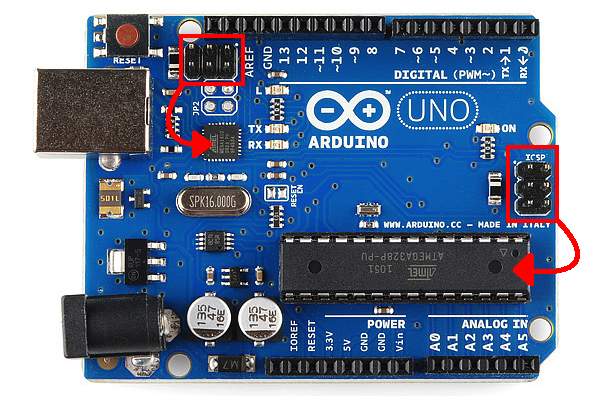 Second, you will probably need a straight 6 pin cable, because the Dragon is expecting to sense a voltage on one of the ISP header pins. It might work though if you use the Dragon in JTAG mode, I have never tried using a cable like you are.
|
|
#
?
Feb 21, 2014 20:57
|
|
|
When I plug it into the other port, all the lit LEDs on the board dim and the Dragon can't read VTarget like it can with the first port. Should I try it on wall power maybe? Flipping the orientation turns off the Arduino until you take it off again, presumably to protect it from the cable being put on backwards
|
|
#
?
Feb 21, 2014 21:19
|
|
|
I'm not sure this is applicable, but when I've used the Dragon to program targets I've either powered it just from the Dragon or not connected the VCC at all. From here: http://www.atmel.no/webdoc/avrdragon/avrdragon.isp_description.html quote:When using off-board targets there should be no connection between the VCC header and pin 2 of the SPI header. It's confusing that you're powering it from both sides? Not sure if I just misread your description.
|
|
#
?
Feb 21, 2014 21:30
|
|

|
This image give you the pin out for the ICSP header.  The "correct" way to do this is with a 6 pin cable going from the ISP header on the dragon to the ICSP header on the Arduino. Any chance you can get such a cable? Or maybe cut down an old floppy drive cable you have lying around?
|
|
#
?
Feb 21, 2014 21:30
|
|
|
JawnV6 posted:I'm not sure this is applicable, but when I've used the Dragon to program targets I've either powered it just from the Dragon or not connected the VCC at all. From here: http://www.atmel.no/webdoc/avrdragon/avrdragon.isp_description.html That quote doesn't apply here. That is saying that if you are trying to program a chip on the Dragon itself, you need to jump from VCC to pin 2 on the ISP header. When you are programming an off board chip though you should just connect header to header. The thing that is goofy in what he is doing is that he is running from the dragon JTAG header over to the arduino's ICSP header. I have never tried that, but if it works at all you'll need to tell Atmel Studio that you are using JTAG, not ISP. Edit: Sorry about the double post. I should have just edited my previous comment.
|
|
#
?
Feb 21, 2014 21:34
|
|
|
armorer posted:The "correct" way to do this is with a 6 pin cable going from the ISP header on the dragon to the ICSP header on the Arduino. Any chance you can get such a cable? Or maybe cut down an old floppy drive cable you have lying around? I took a hacksaw to one end of a floppy cable and just jammed the other end on the Dragon and now I get a device signature and 5V reading.  e: And half an hour later I've set the fuses and burned the bootloader, it's running the Blink program, and I've got stuff on the way to make a proper cable for next time I blow it up so I won't need this monstrosity of a cable.  Now just to make sure from my cursory research, I have to cut the marked reset enable trace to allow Debugwire debugging, after which I have to press the reset button on the board when I'm uploading something until I reconnect them? Why isn't it just a two-pin jumper I can yank when I need to? Luigi Thirty fucked around with this message at 05:03 on Feb 22, 2014 |
|
#
?
Feb 22, 2014 04:25
|
|
|
Luigi Thirty posted:I took a hacksaw to one end of a floppy cable and just jammed the other end on the Dragon and now I get a device signature and 5V reading. Awesome! I'm glad you got it working. As for the reset enable trace, I really don't know because I haven't used the Dragon in the manner that you are.
|
|
#
?
Feb 22, 2014 05:12
|
|
|
Luigi Thirty posted:I've got stuff on the way to make a proper cable for next time I blow it up so I won't need this monstrosity of a cable. To be fair, that is in no way the worst thing I've seen someone do with a floppy cable.
|
|
#
?
Feb 22, 2014 06:53
|
|
|
Well, this is strange. I'm now talking to the card very happily (using an Arduino uno board with an SD shield that can be accessed via SPI, for those just joining us). However, I just went to characterise how many commands I could test in a second (to see if a brute force blind fuzzing technique with no guidance at all is even remotely tractable), and I found that it jams after you send about four commands in a single program. It sends the new command, gets about half way through the 64 byte listening cycle where it just pushes a high line and just...stops. I would assume it was waiting for a response it never recieves, except that's not how SPI works. It would just give back all 255's or all 0's if that were the case. Putting delays between each transfer, even massive ones, doesn't help. I'm not filling up my memory, I just checked. Is there a buffer somewhere that I'm making GBS threads into or something? edit: problem found, the QueueArray library doesn't take kindly to have multiple copies instantiated. Even though the system had lots of memory, it was still being wedged because I was creating lots of queuearrays of commands. This was solved by creating a single global queuearray for commands and another for responses, and clearing them each time a command was sent. I can test 144 commands per second. Sir_Substance fucked around with this message at 01:04 on Feb 25, 2014 |
|
#
?
Feb 22, 2014 14:13
|
|
|
Is anyone actually maintaining Avarice, these days? We've put together a bunch of patches to get various revisions of XMegas working and I have no idea who to send them to for incorporation...
|
|
#
?
Feb 23, 2014 17:15
|
|
|
I need a particular function to be easy to update. This is on a MSP430. I'll have a very, very narrow communication channel to a micro out in the field. It's low bandwidth and might get cut off with only half a message sent. There's one function that contains most of the sensing algorithm. I've already separated out the constants and stuffed them into their own segment. But for the function itself I'm not sure the best approach. By default, the compiler packs it in with the rest of the code. Right now it's taking up 0xe2 bytes, it's reasonable to assume it will stay under the size for a flash segment 0x200. The two main approaches I see are 1) Pin the entire thing out in memory, away from everything else, and rewrite it in place when required. 2) Set up a jump gate and point it to the shipped function, updates are done by writing the new function into memory, then updating the jump gate's segment e: welp, #2 was 3 lines of code leveraging function pointers, didn't even have to muck about linker maps e2: and victory declared all too early, quote:MSP430: File Loader: Data verification failed at address 0x00001000 Please verify target memory and memory map. e3: above was a debug setting in CCS, "erase main memory AND information segments" had to be set. now i'm mucking around in linking, because naively grabbing &sense_algo is showing up as 0xFFFF at the end of compilation. JawnV6 fucked around with this message at 19:54 on Feb 25, 2014 |
|
#
?
Feb 25, 2014 19:02
|
|
|
The fuzzer is now running very effectively and testing 1100 commands per second. I'm going to do a little bit of python based magic to control it from the raspberry PI and have any relevant results forwarded to me via jabber, and then I'm going to leave it to run it's course. If it has to run the entire command set to find something, that'll take 3 months, but that's not really a big deal since it'll do it autonomously and I can have it resume from an arbitrary set of bytes. From there I'll have to do what the guys who got the appotec cards working did, and crack open some cards and see if I can get manuals and stuff for the brands. The sandisk documentation (and I'm using toshiba, but whatever) states that in SPI mode the manufacturer commands are completely disabled, but hey, if they actually had a set of commands for rewriting the firmware in there, they wouldn't tell people, would they? So once the fuzzer is ticking away, it'll be time to go rip some cards apart.
|
|
#
?
Feb 27, 2014 10:41
|
|
|

|
| # ? May 11, 2024 21:38 |
|
|
Are you going to release code?
|
|
#
?
Feb 27, 2014 18:39
|
|