


|
Major  moment. moment.Slanderer posted:I would start by looking at existing soundproofing standards and their test methodologies: I keep thinking that I'm trying to measure vibration, when what I'm really trying to measure is sound. The easiest way to measure sound is probably with a loving microphone durrrr. Contact microphones are probably where I want to start.
|
 #
?
Oct 4, 2015 00:53
#
?
Oct 4, 2015 00:53
|
|


|

|
| # ? May 23, 2024 01:31 |
|
|
Tres Burritos posted:Major Piezo-based contact mics can have a pretty awful frequency reponse, so keep that in mind
|
|
#
?
Oct 4, 2015 00:55
|
|
|
Actually, you may be okay with a piezo contact mic, as long as it is one with a proper preamplifier, and not a bare piezo element. Piezos are electrically "weird wobbly capacitors", and as such will form an RC filter with the standard input impedance of a microphone input. Which very high input impedance preamps, this effect can be mitigated.
|
|
#
?
Oct 4, 2015 01:08
|
|
|
Slanderer posted:Actually, you may be okay with a piezo contact mic, as long as it is one with a proper preamplifier, and not a bare piezo element. Piezos are electrically "weird wobbly capacitors", and as such will form an RC filter with the standard input impedance of a microphone input. Which very high input impedance preamps, this effect can be mitigated. Yeah I have no idea what an "impedance" is, but I'm hoping that I'll have one of these options 1) One stop shop get your mic and your amplifier here trust us it'll be great 2) Some easy to understand reading material that can get me up to speed on microphone stuff quickly
|
|
#
?
Oct 4, 2015 01:16
|
|
|
The results will be rough, but if you want something cheap to experiment with there are instructions for making your own piezo contact mics for stuff like cigar box guitars out there. There are also commercial solutions for acoustic guitars and other acoustic instruments but I think they get up around $40. You'd still require a preamplifier either way mind you, but I'm sure there's plenty of instructions on making those too.
|
|
#
?
Oct 4, 2015 14:19
|
|

|
Slanderer posted:Actually, you may be okay with a piezo contact mic, as long as it is one with a proper preamplifier, and not a bare piezo element. Piezos are electrically "weird wobbly capacitors", and as such will form an RC filter with the standard input impedance of a microphone input. Which very high input impedance preamps, this effect can be mitigated. An impedance transformer seems to have worked. I can pick up music playing from speakers on the surface of my desk. Pretty neato.
|
|
#
?
Oct 6, 2015 03:13
|
|
|
Tres Burritos posted:An impedance transformer seems to have worked. I can pick up music playing from speakers on the surface of my desk. Pretty neato. Awesome, glad to hear it worked out. I have a really good piezo mic somewhere that I need to dig out--it was a super-specialized preamplified and signal conditioned sensor intended for electronic stethoscopes. I had intended to use it to make a "wall scratch" detector user interface for turning on or off a light, but I never got around to finishing it.
|
|
#
?
Oct 6, 2015 03:47
|
|
|
Does anyone have a recommendation for a kit of banana jack hookup and test cables? Stuff like Pomona model 6249 Minigrabber (way more so that other grabbers, it's the best for securely hooking up to a ground clip or ground wire): http://www.amazon.com/Pomona-MiniGrabber-Test-Banana-Black/dp/B0000WU3L4 Also need standard banana->alligator, banana-> IC clips, shrouded/protected banana cables, etc... Sorry for being so vague, but our lab here is pretty low on test cabling nowadays, and I want to order a few sets of good test leads for me and the people in my group. I reguarly have to wire up various combinations of multi meters, power supplies, DC loads, and test PCAs, so I need more than just a multimeter test kit. Slanderer fucked around with this message at 15:41 on Oct 6, 2015 |
|
#
?
Oct 6, 2015 15:37
|
|
|
Slanderer posted:Does anyone have a recommendation for a kit of banana jack hookup and test cables? Stuff like Pomona model 6249 Minigrabber (way more so that other grabbers, it's the best for securely hooking up to a ground clip or ground wire): A while ago I came across these $2 test leads and decided to order 10 sets of them: http://www.newark.com/tenma/72-9350/test-lead-set-black-red-1-2m-1kv/dp/86T2029 Also got this clip assortment: http://www.amazon.com/Alligator-Clip-Assortment-Electrical-60/dp/B002X4CG3A And just started making my own custom leads. Some of the leads I cut in half and make into two half length leads, others I use the full 1.2m length They are shrouded on both ends, but if you want unshrouded its easy enough to clip off the shroud with careful application of diagonal cutters. Some examples:   Oh and I have a pair of these that are pretty nice alligator style with very fine teeth and well insulated http://www.amazon.com/gp/product/B0012W2Q3E I haven't really had need for minigrabber stuff, but no reason you couldn't splice some on the ends of these if needed.
|
|
#
?
Oct 6, 2015 22:41
|
|


|
Oh and I made some POEWR! cables for um jump starting cars I guess   8awg Turnigy silicone wire black: http://www.hobbyking.com/hobbyking/store/uh_viewItem.asp?idProduct=43353 red: http://www.hobbyking.com/hobbyking/store/__9677__Turnigy_Pure_Silicone_Wire_8AWG_1mtr_RED_.html And metal banana plugs BNNMTR BNNMTB from here http://www.futurlec.com/Banana-BananaPlugs.shtml
|
|
#
?
Oct 6, 2015 23:16
|
|
|
Question: How do I read Figure 10 here? http://www.analog.com/media/en/technical-documentation/data-sheets/AD8361.pdf I understand conceptually that the linear relationship becomes non-linear at the high and low end of the input range, but reading the graph, what exactly does (say) -3dB @ 0.02 Vrms mean? The gain is nominally 7.5 Vout/Vin - a voltage ratio - so how does a dB measure factor in here?
|
|
#
?
Oct 7, 2015 04:33
|
|

|
rawrr posted:MX500 - the current iteration, and some models have a display that shows power level. Has two ports for two handpieces, but can only use one at a time. MX5200 lets you use both ports simultaneously. Love switching between the talon and a chisel tip  Only problem with the metcal is that when it goes to sleep you have to manually power cycle it, or replace the tip, to get it to wake up. What's the loving point?
|
|
#
?
Oct 7, 2015 14:02
|
|


|
Cyril Sneer posted:Question: How do I read Figure 10 here? http://www.analog.com/media/en/technical-documentation/data-sheets/AD8361.pdf ANIME AKBAR fucked around with this message at 14:21 on Oct 7, 2015 |
|
#
?
Oct 7, 2015 14:10
|
|
|
ANIME AKBAR posted:The y axis is the gain error of the detector's output vs its ideal linear response. So if the ideal gain is Vout=Vin*7.5, then the Vout is always guaranteed to be within Vout=Vin*7.5*10^(error/20), where error (in dB) can be anything within that shaded area. I think you might be confusing dB with dBm or dBv. Thanks, this makes perfect sense.
|
|
#
?
Oct 7, 2015 17:47
|
|
|
I'm incredibly confused about zeners. Assuming I can clamp voltage to some degree with only a zener and a resistor, how do you go about choosing a resistor value? Say I have a MCU with 5V logic, and I want to protect a digital input to allow me to give it 5V to 24VDC logic high. The differential impedance or resistance is what is really throwing me off, the datasheets often provide one value at a specific current but the reistance also varies wildly at different current levels. Here's a datasheet: http://global.oup.com/us/companion.websites/fdscontent/uscompanion/us/pdf/microcircuits/students/zandr/1N750A.pdf First of all, say I'm looking at 1N751A on that sheet(nominal 5.1Vz), since it is one of the values charted on the second page. The eletrical characteristics table says Zz = 17 Ohm @ Iz = 20 mA , but then the chart on the next page seems to show ~2.5 Ohm @ 20mA. Secondly even if any of this data was self consistent, what the hell does it even tell me. I've tried a few calculations but end up with wildly varying voltages that don't make any sense. peepsalot fucked around with this message at 23:04 on Oct 7, 2015 |
|
#
?
Oct 7, 2015 22:56
|
|
|
peepsalot posted:I'm incredibly confused about zeners. Assuming I can clamp voltage to some degree with only a zener and a resistor, how do you go about choosing a resistor value? The R here is telling you the slope of the voltage at a specific current on a voltage vs current chart. So it's telling you how much voltage is going to change in relation to a current change right around the zener voltage So the 4.7V zener has an R of 19 ohms at 20mA. That means if you went up another 5mA to 25mA it would add 0.005*19 or ~0.1V to the voltage at the zener. Note that I chose only 5mA because the number changes pretty widely as current deviates from the benchmark (as you can see on the chart of impedance vs current). For your application you want to chose the resistor between the input and the zener such that it limits current to ~20mA or less at a worst case of 24Vin. So that's ~1k or higher. I'd probably go 10k which falls well under 1/10th of a watt and will work with any package. I generally ignore the impedance number and reference the V vs I chart instead over my expected ranges of currents. You need to watch out for low value zeners below about 4.7V because their properties are terrible. Fake edit: Right, on a quick look I don't know how to reconcile the numbers given in the table with the chart. The 5.1V zener shows ~3 in the graph and 17 in the chart. It may be typical vs worst case.
|
|
#
?
Oct 8, 2015 01:21
|
|

|
peepsalot posted:A while ago I came across these $2 test leads and decided to order 10 sets of them: After looking at the prices of individual jumpers from Pomona, I'm inclined to just get a big order of connectors and have the technicians here just make up cables whenever they have time. At some point it takes longer for me to shop for a full order of the "right" cables than it does for a tech to knock out a half dozen that are good enough
|
|
#
?
Oct 8, 2015 06:03
|
|
|
Slanderer posted:After looking at the prices of individual jumpers from Pomona, I'm inclined to just get a big order of connectors and have the technicians here just make up cables whenever they have time. At some point it takes longer for me to shop for a full order of the "right" cables than it does for a tech to knock out a half dozen that are good enough Well it's probably worth having good premade cables for standard things but bananas and aligators come standalone in a way that's easy to make into a cable. I particularly like bananas that have both male and female because it makes it easy to daisy chain which is often necesary when debugging to add additional sources/scopes/meters to a circuit. Our tech has a good supply of those on hand and I ask her to use them a lot.
|
|
#
?
Oct 8, 2015 18:01
|
|
|
This is clever as hell https://www.youtube.com/watch?v=C-AfmLggE28
|
|
#
?
Oct 9, 2015 07:57
|
|

|
I need some help calculating zener diodes values. I killed my raspi by shorting 7-8volts into the gpio pins so I went and bought 4 types of zener diodes: 5.1v 1/2 watt+1 watt, 3.3v 1/4 watt and 1/2 watt and set up the following circuit via trial and error:  I have 3 different voltages. 3.3v, 5v, and 12v. When I provide 3.3 volts, all three LEDs light up. When I provide 5 volts, only the 2 on the right light up, and when I provide 12 volts, only the right LED lights up. However, what sort of baffles me is that the only zener diodes I could get to work in these positions are 5.1 volts. If I used a 3.3 v zener diode in the left position, the leftmost LED would illuminate a tiny bit. Is this because the voltage and current are being dropped by the middle/rightmost LED? I'm trying to understand this here: http://www.petervis.com/Raspberry_PI/Raspberry_Pi_GPIO_Header/Raspberry_Pi_GPIO_Header_Pin_Protection.html nevermind, I think the shop just mis-labeled the packages. Appears to be working now
|
|
#
?
Oct 9, 2015 12:15
|
|

|
BattleMaster posted:This is clever as hell A few years back this exact idea occurred to me, but the catch is the LEDs are going to be experiencing a large peak-to-average ratio of current. Even if the ripple is fast enough to not produce flicker, this means that the LEDs can't be run at full power (without harming them long term). Also without a line filter there's no way this would pass EMC. The fact that all the LEDs seem to have roughly the same bias seems to imply the switching scheme is actually more complicated than what he drew. There are likely switches shunting LED groups, allowing some LEDs to be bypassed sometimes so that they can be forced to share average current more equally. Also it's interesting that there's no input voltage sensing, I guess works by guessing at the initial phase of the input, and figuring out the appropriate switching sequence by observing only the current.
|
|
#
?
Oct 10, 2015 12:54
|
|
|
I'm struggling trying to mesh two seemingly contradictory concepts in power measurement. This is going to be a bit long, so bare with me. I have an application where I need to maintain a constant power dissipation ("net power") from a variable load. To do this, there is a 4-port coupler just before the load connection where the power appearing at the forward and reverse coupled ports is monitored, and the net power and SWR then calculated (of course, there's some intervening amplification and digitization circuitry). I'm trying to work out what the accuracy would be on my measurement of the net power and load SWR, as a function of desired net power and actual load SWR. Working through the math (I'm using a coupler with ~20dB coupling coefficient and ~35dB directivity), I've come up with plots like this: http://imgur.com/a/mRA2l Figure 1 shows that, for example, at a desired net power of 10W and load with an SWR of 5, I can expect my measurement to fall somewhere between 9 - 11 W. Alternatively, the second plot shows that for loads with increasing SWR, my estimate of the SWR becomes steadily less accurate (due to less accurate measurement of the forward and reflected powers). This falls in line with my intuitive understanding of coupler behaviour: as the load mismatch increases, to maintain a fixed net power, more forward power is needed. Thus, more forward power is erroneously coupled to the reflected port. Similarly, there is also greater reflected power, and therefore more reflected power erroneously appears on the forward port. This also matches my bench observations. When I connect a load with an SWR ~1, I get quite good measurements for the forward and reflected powers (and hence also the net power and SWR). As I attach loads with greater SWRs, my measurements of forward/reflected power become less and less accurate. Now here's where it all goes awry. What I've just described seems to be completely contradicted by the articles listed here (note that these all use return loss instead of SWR): http://www.markimicrowave.com/Assets/appnotes/directivity_and_vswr_measurements.pdf http://www.wetterlin.org/sam/Reflection/ManualReturnLoss.pdf There are lots of other articles floating around out there that reproduce similar graphs. The graphs show show the complete opposite of what I presented above. That is, that small SWRs (large RL) should be less accurate than large SWR (small RL)! Now, I guess I sort of get that for very well-matched loads (low SWR / large RL) the reflected power is so small so as to be swamped out by internal device reflections and such; but its not sitting well with me that graphs such as Fig. 6 (first link) seem to go completely against my earlier discussion. What gives? What am I missing here? This is seriously driving me loopy.
|
|
#
?
Oct 10, 2015 19:31
|
|
|
ANIME AKBAR posted:A few years back this exact idea occurred to me, but the catch is the LEDs are going to be experiencing a large peak-to-average ratio of current. Even if the ripple is fast enough to not produce flicker, this means that the LEDs can't be run at full power (without harming them long term). Also without a line filter there's no way this would pass EMC. His schematic is wrong compared to ones I've found for the same chip. He put the resistor in the wrong place. Edit: Oh, it was a simplification, but yeah I don't think it works like he drew it  All the magic is happening in the IC but without the datasheet explaining it, who knows. BattleMaster fucked around with this message at 19:48 on Oct 10, 2015 |
|
#
?
Oct 10, 2015 19:43
|
|
|
Cyril Sneer, I don't know how to explain your measurements, but I can point out an error in your reasoning.Cyril Sneer posted:This falls in line with my intuitive understanding of coupler behaviour: as the load mismatch increases, to maintain a fixed net power, more forward power is needed. Thus, more forward power is erroneously coupled to the reflected port. But at the same time, when the return loss is becoming crappy, there is more reflected power coupled to the reflected sense port. In fact, under the condition of delivering a constant power to the load, the increase in reflected power must be in greater proportion than the increase in power incident upon the coupler, if the return loss of the load is less than 0 dB. So, the leakage forward signal appearing at the reverse sense port increases less dramatically than the intended backward sense signal. Therefore, the ratio of the intended to unintended signal at the reverse power sense port improves and the reverse power measurement becomes more accurate when the return loss becomes MORE crappy. For example, if the return loss goes from -20dB to -10dB, that's a 10x higher reflected power coming from the load, which means that 10x higher reflected power is sensed in the reverse power measurement. The incident power only needs to increase by 1.1x though to maintain the same power delivered to the load, so the leakage signal only increases by 1.1x in the reverse power measurement.
|
|
#
?
Oct 11, 2015 02:53
|
|

|
Dug out the soldering iron for the first time in quite awhile today. My partner's Fender Bassman 60 has been having problems for quite some time, requiring pressure to be put in the input cable just so for it to work, so I finally decided to take it apart and try to fix it. I knew it was either that the springs in the jack were bent out of alignment or the thing had come loose from the board, since the plug wiggled in the faceplate like the proverbial hot dog in a hallway. Got it open enough to see the part, it looked like it made contact with the plug just fine, and the whole thing moved. I took out some more screws to get the PCB off its sled and see under it, and: 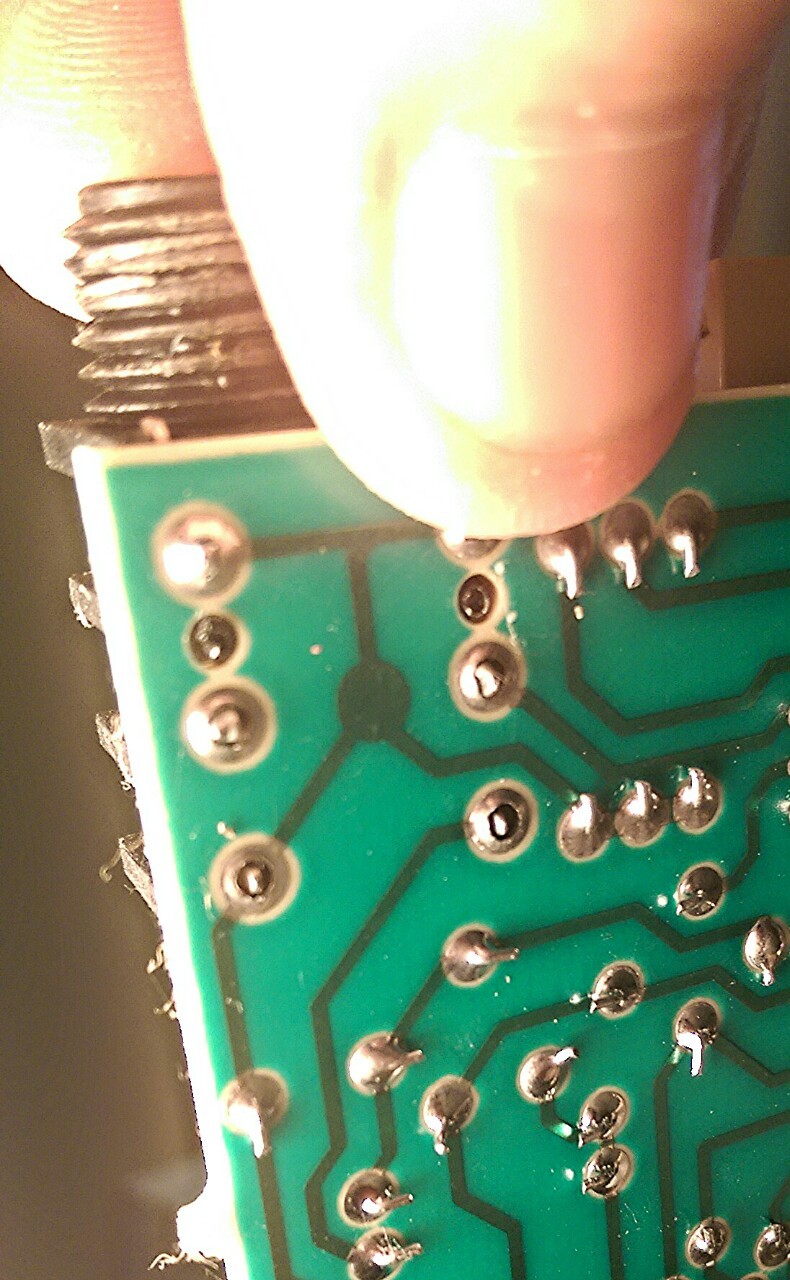 Yep, there's your problem. (My fingers on the input jack, slightly pressing it to and fro, respectively. I don't know why a guitar amp has a stereo jack, but note the third pair of pins). I resoldered all six pins (only the farthest pair were actually completely broken off, but as you can see the others' joints weren't in the best shape either), and it seems to be working properly now. I tested it by using a 1/4" to 3.5mm adapter to plug it into the headphone jack of my computer and playing the main theme from Pacific Rim: https://www.youtube.com/watch?v=1vU7XqToZso  And now I can never listen to that track again, even in the cinema and especially not through headphones, without feeling disappointed. And now I can never listen to that track again, even in the cinema and especially not through headphones, without feeling disappointed.  (if that foghorn note at the end doesn't shake things off shelves and give you a sense of visceral terror, you don't have enough bass.) (if that foghorn note at the end doesn't shake things off shelves and give you a sense of visceral terror, you don't have enough bass.)
Chillbro Baggins fucked around with this message at 20:38 on Oct 11, 2015 |
|
#
?
Oct 11, 2015 20:34
|
|
 Bad Angus! Bad!
|
Cyril Sneer posted:There are lots of other articles floating around out there that reproduce similar graphs. The graphs show show the complete opposite of what I presented above. That is, that small SWRs (large RL) should be less accurate than large SWR (small RL)! Maybe you were misinterpreting return loss? Higher return loss means SWR is lower. For reflected power measurement, the trend is flipped. If you have a very well matched load, you expect practically no reflected power at all. That means poor directivity is going to kill your accuracy. The general rule of thumb is that if your directivity isn't at least twice your return loss, your reflected power measurements are going to be poo poo. edit: now for your measurement of total absorbed power, which is the difference of the forward and reverse measurements, both are going to factor in. But nothing I've read contradicts that. ANIME AKBAR fucked around with this message at 12:40 on Oct 14, 2015 |
|
#
?
Oct 14, 2015 00:49
|
|
|
I'm having trouble with my relay controller circuit. I've got a ESP8266 microcontroller's GPIO pin switching a MOC3023 triac via a 100 ohm resistor. The high side of the triac energises a high current relay. This works with no problems if the power to the ESP is already present before connecting MOC/relay. If the circuit is powered up with everything connected, the ESP doesn't start properly. I assume the ESP is powering up with GPIO high (I've explicitly coded it not too) but I can hear the relay switching on. My gut instinct is an inrush current is causing the ESP to lose power on startup when the triac receives power and it never recovers until power cycling with triac disconnected. 1) Is this a sound theory? 2) Is the solution to put a capacitor between the GPIO pin and the Triac/resistor? If so, what type/value? 3) Could it be something else?
|
|
#
?
Oct 17, 2015 16:03
|
|


|
Jamsta posted:I'm having trouble with my relay controller circuit. Is this all on the same supply? With that opto there isolating things if the relay is on a separate supply and you've laid this out well it will ideally have zero impact on the micro. And I wouldn't expect the MOC3023 current to be enough to droop the micro supply itself. If they're on the same supply it's possible the inadvertent triggering of the relay is drooping the micro power supply as it comes up (if you have a scope look at the supply rail). But in general you want to plan for the start-up condition of the micro. If it's weak pull-up, then add a pull-down to counteract it and you'll only get a high when you purposely drive one. 1.5K is enough on most IC's I've worked with. Or, better, flip the opto control around so the default state of the micro GPIO is OFF for the opto. Also if they're on the same supply you may want to revisit your grounding and power layout. When you have independent circuits you will ideally have independent feeds from the power supply so resistive drop caused by current in one circuit doesn't impact the other (plus good bypassing etc).
|
|
#
?
Oct 17, 2015 17:39
|
|
|
asdf32 posted:But in general you want to plan for the start-up condition of the micro. If it's weak pull-up, then add a pull-down to counteract it and you'll only get a high when you purposely drive one. 1.5K is enough on most IC's I've worked with. Or, better, flip the opto control around so the default state of the micro GPIO is OFF for the opto. They're on the same circuit, so I tried a 1.5K pulldown with only a meter on the end. Wouldn't boot at all. Looked at the specs of the micro and it turns out the IO pin in question to be floating or high for it to boot! I switched to another pin, and it all worked as expected. I shoulda check the specs more carefully when designing this! Thanks for your input.
|
|
#
?
Oct 17, 2015 18:55
|
|
|
Jamsta posted:They're on the same circuit, so I tried a 1.5K pulldown with only a meter on the end. Wouldn't boot at all. All the pin re-use on micro's can be a real pain. Trying to find all those land mines in the various app notes and multi hundred page datasheet/manual is half of the design effort for a reasonably complex chip.
|
|
#
?
Oct 17, 2015 23:56
|
|
|
Microchip is pretty good about putting tables in their datasheets for the complete pin usage all in one place. It's even better now that their newer PIC16Fxxxx parts have fully remappable digital peripherals.
|
|
#
?
Oct 18, 2015 00:06
|
|
|
Do they make breadboards in different pitches? How the gently caress do I even figure out what pitch a particular component is in general? Also I need something that will fit the footprint of a specific surface mount chip but essentially let me break out those pads into loose wires, if such a thing exists. I really do not want to try and solder wires directly to a board.
|
|
#
?
Oct 21, 2015 23:46
|
|


|
SniperWoreConverse posted:How the gently caress do I even figure out what pitch a particular component is in general? Try searching "breakout board" along with your component, if it's something arduino-friendly chances are it exists.
|
|
#
?
Oct 22, 2015 00:31
|
|

|
SniperWoreConverse posted:Do they make breadboards in different pitches? Standard breadboards are 0.1" pitch, I don't recall ever seeing one that wasn't but I've never looked. Most old thru-hole components work on a 0.1" grid e.g. 1/4W thru-hole resistors are 0.3" long by 0.1" wide, etc. To figure out the pitch for a particular component first determine what package type it has (DIP, SOIC, TO-92, etc) and do a google search for the package name + "dimensions". You'll find a bunch of dimensioned drawings to use. To match a surface mount chip to some other format, google for the package name + "breakout board". You can find breakout boards that terminate in plated thru-holes to put wires on or with an array of pins on a 0.1" spacing that will fit into your breadboard. e:f,b while typing
|
|
#
?
Oct 22, 2015 00:38
|
|

|
My LEDs are haunted. I while back, I made this PCB that acts as a big daisy-chainable two-digit 7-segment display using the WS2803D and discrete LEDs. Here's the first instance of it, a sign that shows "4561" with some animations mixed in:  ^ Looking good! Here's the circuit -- it's pretty simple:   That sign works great and all was fine. Then, a few weeks ago, I decided to populate a few more of the boards in the exact same way to make a clock. It worked great for the first day, then LEDs started dimming out or dying altogether, despite using the exact same LEDs!  ^ Why you so crappy???? The LEDs are under gaffers tape to diffuse the light. There are two LEDs out entirely on the '6', one on the '4', and the whole upper left part of the '0' is half dead! It's the same drat circuit as the earlier display shown above, with LEDs from the same sack and the same value resistor for current limiting on the WS2803 (1k). It's not a bad connection, since it doesn't react to wiggling of any part of it, and anyway, the LEDs are in series, so if one dies, the whole segment should die. I thought maybe I got a some bad LEDs in this batch, so I took a bunch and ran them in multiple 4-long series at 12V without current limiting of any kind for the past 3 days straight, and they're still going strong:  ^ But you're *not* dead? WTF?? I'm at a loss -- any guesses on what to check next? Stabby McDamage fucked around with this message at 04:07 on Oct 24, 2015 |
|
#
?
Oct 24, 2015 04:02
|
|

|
That thing is awesome! Way better than what I've built! I am a complete amateur here, but I suspect that your LEDs and ICs are not getting enough voltage/amperage. I have no idea how it worked for a day before it started to break down, but I suspect you have reached the amperage limit of your LM7805/power supply(I only see one on your rightmost board, and I don't see any heat sink, they tend to get quite hot). The LM7805 might output 1.5A, you've got 120+ LEDs. Those LEDs are passing current but aren't bright enough to "see". This probably explains why the leftmost digit doesn't 'light'. Use a multimeter to see what the 5v level on VCCout on your first module is really at. Then check the 2nd. My bet is you've reached the limit of your power source.
|
|
#
?
Oct 24, 2015 05:34
|
|
|
politicorific posted:That thing is awesome! Way better than what I've built! I hear you, except the 7805 is only there for logic voltage. The LEDs run on the raw 12V (or whatever big enough voltage) in, and the regulator just steps it down for the AVR chip and logic part of the WS2803 chips. It gets hot but you can comfortably touch it. I've tried giving it 24V (by hooking it to the -12V and +12V of my "power supply", a crappy ATX power supply with binding posts), and I get the same result. Also, I put a meter on the 5V rail during both 12V and 24V operation and I get a consistent 5V. EDIT:  The resistors I have on the new board are 10k, not 1k, because I'm an idiot hell moron who can't tell orange from red. Fixing now. Stabby McDamage fucked around with this message at 05:47 on Oct 24, 2015 |
|
#
?
Oct 24, 2015 05:38
|
|
|
Do the chips get hot? What happens if you swap them out? edit: hah. nice.
|
|
#
?
Oct 24, 2015 05:49
|
|

|
How does the soldering look on the board? If you shorted the connection of any led with solder then that would definitely make it go dark while others in the string still light.
|
|
#
?
Oct 24, 2015 05:51
|
|
|
|
| # ? May 23, 2024 01:31 |
|
|
Fixed just by using the right drat resistors. ughhhhhhhhhhhhhhhhhhhhhh this thing has been driving me nuts for over a week. Well, now it works. Stabby McDamage fucked around with this message at 06:22 on Oct 24, 2015 |
|
#
?
Oct 24, 2015 06:13
|
|