

|
Spreading low powered control all over the house seems a bad way of doing this. AVRs in walls aren't standard for a reason. Generally you have centralised control with dumb terminal style android tablets or whatever mounted for control.
|
 #
?
Jan 26, 2017 16:22
#
?
Jan 26, 2017 16:22
|
|


|

|
| # ? Jun 8, 2024 06:47 |
|
|
Anyone got a good news site with an embedded focus? It'd be nice to hear when popular projects have updates, interesting tools are released and new products come out. Just want to stay up to date on the industry.
|
|
#
?
Jan 26, 2017 18:30
|
|


|
Arachnamus posted:The thing I'm getting at is that I'm comfortable solving infrastructure issues like data, electricity, cabling, and maintenance access, it's just the hardware that I'm looking for help with. Ok, great! Arduino has a tendency to attract hobby-grade practices. I couldn't get the mental image of someone stabbing through 12awg wires to power an arduino with dodgy connections to a 12V relay on the mains socket in a pitched race to figure out which would burn down first. If you're confident you have all of those issues under control, there are a few other threads to check out. The RPi thread can help you out with those and other SBC's. The Arduino thread can help with ESP8266 and similar things. If I was doing something and budget wasn't a concern, I'd go for SBC's. I don't know what the state of the art ESP8266 update path is (full flash over wifi yet?), but for a SBC you can definitely just ssh into it and upgrade whatever sensor/control software you're running. For really fast bringup on a new component it's really nice to write python on a raspberry pi instead of C on an arduino.
|
|
#
?
Jan 26, 2017 18:57
|
|

|
JawnV6 posted:Ok, great! Arduino has a tendency to attract hobby-grade practices. I couldn't get the mental image of someone stabbing through 12awg wires to power an arduino with dodgy connections to a 12V relay on the mains socket in a pitched race to figure out which would burn down first. If you're confident you have all of those issues under control, there are a few other threads to check out. The RPi thread can help you out with those and other SBC's. The Arduino thread can help with ESP8266 and similar things. 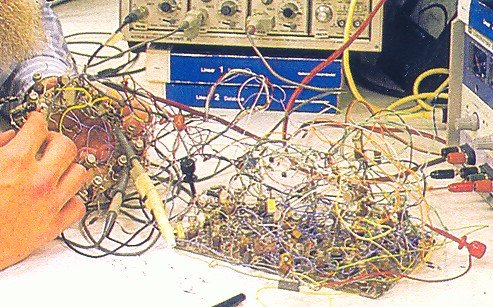 Just jam 120v connection into the two banana plugs and you're good to go.
|
|
#
?
Jan 26, 2017 20:19
|
|


|
csammis posted:I really don't want to discourage creativity but f I were buying a house and I saw "bespoke smart home system designed by current owner, by the way you'll have to tear the house apart to remove or fix it" on a seller's disclosure - you would disclose that, right, and not just leave a letter for the new owners on closing day? - I'd run so loving fast the realtor would get wind chapped. Maybe you're not worried about or thinking about resale value right now but consider what JawnV6 said about physical access to the boards for changes / maintenance that you'll be doing. Do you really want to tear up a skirting board to fix a loose wire, then nail it back down and repaint? I'll go out on a limb and say that no, you don't. dougdrums posted:I feel like putting wireless devices in the walls will also cause some strange problems. Either way, I wouldn't put an uncased electronic devices in my walls due to fear of fire. Guys it's OK, I'm not a dumb dumb, I'm not going to tape an uncased arduino to a brick and plaster over it. I've not gone into detail on the installation of them because that's not the problem I'm trying to solve right now. They will be somewhere sensible, cased if appropriate, with some kind of panel access. But I do thank you for your concern. csammis posted:If I were renovating a house and wanted to get creative with the hacker-friendly amenities, I'd run a 5V DC ring and the fastest Ethernet available to empty 2-gang boxes in every room of the house. That way you have a nice little niche everywhere to put your microcontroller projects that isn't a permanent installation or hard to access. I was wondering about a 5V ring, but aren't the voltage drops significant for DC even over those sorts of lengths? JawnV6 posted:Ok, great! Arduino has a tendency to attract hobby-grade practices. I couldn't get the mental image of someone stabbing through 12awg wires to power an arduino with dodgy connections to a 12V relay on the mains socket in a pitched race to figure out which would burn down first. Ah, I understand. No, any power stuff I run will be done by the sparky and signed off by building regulations. I like my face unburnt. JawnV6 posted:If I was doing something and budget wasn't a concern, I'd go for SBC's. I don't know what the state of the art ESP8266 update path is (full flash over wifi yet?), but for a SBC you can definitely just ssh into it and upgrade whatever sensor/control software you're running. For really fast bringup on a new component it's really nice to write python on a raspberry pi instead of C on an arduino. I did look into those first (RPis and CHIPs) but they're quite large and geared towards uses I don't have for the most part, like I won't need HDMI in most cases, plus they have availability issues, in the UK at least. Thanks for the thread links ")
|
|
#
?
Jan 26, 2017 20:25
|
|


|
Arachnamus posted:I was wondering about a 5V ring, but aren't the voltage drops significant for DC even over those sorts of lengths? Yeah, I wasn't thinking about the voltage drop over house-length runs 
|
|
#
?
Jan 26, 2017 20:48
|
|

|
csammis posted:Yeah, I wasn't thinking about the voltage drop over house-length runs Can't you just run it off a constant-voltage supply?
|
|
#
?
Jan 26, 2017 21:16
|
|


|
Stick your iot poo poo in electrical gangboxes. Easy to service and any electrician can add or remove them.
|
|
#
?
Jan 26, 2017 21:22
|
|

|
csammis posted:Yeah, I wasn't thinking about the voltage drop over house-length runs Further advantages of gangboxes: you can mains to them and put in a cute little power supply. Don't tell your home insurer!!!!
|
|
#
?
Jan 26, 2017 21:23
|
|
|
Malcolm XML posted:Further advantages of gangboxes: you can mains to them and put in a cute little power supply. Hah, I suggested gangboxes in my first post on the topic...when the voltage drop topic came up my first thought was "Well you could just put mains to it and stick a power supply on the back of it" and my second thought was "excellent way to start a house fire!" Munkeymon posted:Can't you just run it off a constant-voltage supply? I was imagining running several 5V taps off a single supply, and I'm not an expert (obviously), but the voltage drop problem would require that all runs from the supply would be exactly the same length to deliver the same voltage at the tap...right?
|
|
#
?
Jan 26, 2017 21:30
|
|
|
csammis posted:I was imagining running several 5V taps off a single supply, and I'm not an expert (obviously), but the voltage drop problem would require that all runs from the supply would be exactly the same length to deliver the same voltage at the tap...right? I don't think the tolerances have to be that exact. With 18 gauge wire you're talking about ~0.02 Ohms/M (no, my memory isn't that good - I just looked it up)
|
|
#
?
Jan 26, 2017 21:38
|
|
|
Munkeymon posted:I don't think the tolerances have to be that exact. With 18 gauge wire you're talking about ~0.02 Ohms/M (no, my memory isn't that good - I just looked it up) When I was looking at these kind of boxes I used a calculator and it seemed like the percentage of drop was significant if you're starting at 5V. Starting at 12V might be an idea because the drop would be to around 11V iirc and you can use simpler voltage regulators to get that down to 5V. I'd want to run that by a real electrician first, though.
|
|
#
?
Jan 26, 2017 22:16
|
|
|
csammis posted:Yeah, I wasn't thinking about the voltage drop over house-length runs 5 volts will probably be fine. The 8266 is a 3.3v device, and the huzzah has a regulator on it. Its dropout voltage is .25 volts, so you only need 3.55v at the board. If we assume a 300 ma draw, (up to 250ma for the 8266, and another 50 for the sensors) you'd need over 240 meters of .02 ohm/m wire before voltage drop would be a problem. If you bumped the supply voltage to 6v(which adafruit recommends for heat issues, though the regulator circuit should work until 12. Read the documentation to see exactly what it's deal is) you'd have to go over 400m before you'd have a problem
|
|
#
?
Jan 26, 2017 22:53
|
|

|
Aurium posted:If you bumped the supply voltage to 6v(which adafruit recommends for heat issues, though the regulator circuit should work until 12. Read the documentation to see exactly what it's deal is) you'd have to go over 400m before you'd have a problem Very interesting. I wasn't expecting something that small to have a regulator that would work up to that high a voltage.
|
|
#
?
Jan 26, 2017 23:19
|
|
|
TTerrible posted:Spreading low powered control all over the house seems a bad way of doing this. AVRs in walls aren't standard for a reason. Generally you have centralised control with dumb terminal style android tablets or whatever mounted for control. Groverduinohaus
|
|
#
?
Jan 26, 2017 23:41
|
|


|
Arachnamus posted:Guys it's OK, I'm not a dumb dumb, I'm not going to tape an uncased arduino to a brick and plaster over it. I've not gone into detail on the installation of them because that's not the problem I'm trying to solve right now. They will be somewhere sensible, cased if appropriate, with some kind of panel access. But I do thank you for your concern. Isn't it? I'm really confused ... I'm not sure how much is hyperbole, but you're talking about putting a $2 wireless microcontroller into a relatively expensive wall enclosure ... I mean, I personally know and grew up with some people who design and work with these sort of systems. On occasion I have even worked with them, which is why I read this thread. I'm not insulting your intelligence; You're certainly aware that what you're requesting is strange, and possibly no poo poo dangerous. It's just that if you want household programmable led strip fart detectors or whatever to mess with, there are cheaper and simpler ways to do it that aren't exactly secrets. Like there are so many reasons why they run AC power and ethernet instead of this. I mean y'all have been to a rock concert, right? Couldn't you just get the outlets with 5v already built in, and just mount it on the wall like a thermostat? Or just mount them on the wall like thermostats? Or buy a modern hackable network thermostat? dougdrums fucked around with this message at 04:11 on Jan 27, 2017 |
|
#
?
Jan 27, 2017 03:56
|
|
|
Netgear also makes a device called the EX2700 I think. It is small enough to fit in the palm of your hand, and comes with an AC supply attached. They can be modified to use powerline if you want. There are just so many better approaches to this.
|
|
#
?
Jan 27, 2017 04:14
|
|
|
dougdrums posted:household programmable led strip fart detectors or whatever The Something Awful Forums � Discussion � Serious Hardware / Software Crap � The Cavern of COBOL � embedded household programmable led strip fart detectors or whatever
|
|
#
?
Jan 27, 2017 05:00
|
|

|
I bought ten methane detectors a while ago in an effort to heat my house with grass clippings so you might understand why I'm so concerned about house fires.
|
|
#
?
Jan 27, 2017 05:28
|
|
|
Arachnamus posted:Very interesting. I wasn't expecting something that small to have a regulator that would work up to that high a voltage. A ton of the adafruit stuff has onboard regulators because they know that most people want to use 5v (and most modern stuff is 3.3v) or just straight up power it with 12v (and nothing runs on 12v). Most linear regulators can take 30-36v, though they're still limited by the external input capacitors. (which are frequently in the 20vish range for cost reasons) At that point you're limited more to how much current you can draw. For example regulating from 35v to 5v you'd be limited to around 30ma current, if you limit yourself to 1w dissipated by the regulator. If you have an unheatsinked to220 regulator 1w is basically acceptable, if you have a smaller one it's decidedly over ambitious. If you need to dissipate more power than that in the regulator you're probably doing something wrong. Munkeymon posted:Can't you just run it off a constant-voltage supply? Most (practically all) modern power supplies are constant voltage supplies. The problem is that they measure the voltage right at their output, which is to say before it drops in the wire. You can sense at the load, but it requires running additional sense wires. Unless you need the precision brought by load sensing, it's typically easier to run thicker wires instead of twice the number of wires. If you have a stable load, and can spend the additional engineering effort, you could bump of the voltage by a known and set amount. For what it's worth, that's not the case here as microcontrollers are highly variable loads. For example, the 8266 can draw up to 250ma, but that's when transmitting. In standby it's more like 10ma-50ma. yippee cahier posted:Anyone got a good news site with an embedded focus? It'd be nice to hear when popular projects have updates, interesting tools are released and new products come out. Just want to stay up to date on the industry. Definitely not professional grade, but if you don't read hackaday you should. dougdrums posted:Isn't it? I'm really confused ... I'm not sure how much is hyperbole, but you're talking about putting a $2 wireless microcontroller into a relatively expensive wall enclosure ... First, if all he wants is something reliable and does mostly it's own thing, that's probably the better option. If what he wants to do is learn or do something somewhat bespoke he could do much worse than being aware than he's asking for something a bit weird. One of the best ways to learn something is by using it to do something you're interested in. I don't think I'd put something just randomly in the middle of an unmarked wall, but I might put something behind a wall switch/plate/thermostat style like you're talking about. As far as power, cheap wall adapters are kinda poo poo. They work well for consumer devices because when you're buying 10000, your 5 dollar adapter is of vastly superior quality to the 5 dollar adapter I can buy as a one off. Inside plug adapters are even worse. Good ones are priced as novelties for the person who wants one in their entire house for use by their night stand, and is willing to pay for it. Just about everyone else is about shaving every penny off possible. I'd trust a single good 5v power supply wired across the house before I'd trust a bunch of cheap power supplies off amazon. Particularly if we're possibly talking in the wall where you'd have no chance to see smell or hear it going bad. This is one of the reasons PoE took off in the first place on the commercial side.
|
|
#
?
Jan 27, 2017 05:55
|
|
|
dougdrums posted:Isn't it? I'm really confused ... I'm not sure how much is hyperbole, but you're talking about putting a $2 wireless microcontroller into a relatively expensive wall enclosure ... My original request was: quote:I'm trying to find the best [microprocessor] combination of small, cheap, relatively easy to wire (I'm comfortable with solder), and it's gotta be on the network, either wired or wifi (but wifi for preference). I'm not sure how that's incompatible with what you're saying here. I mentioned some SBCs and arduino because those are the things I'm (sort of) familiar with, but I didn't mention voltages or DC vs AC. I expressed a preference on wireless over wired because it reduces the amount of network patching and switching required but otherwise I'm open to whatever is the best solution. I was pushing back on the installation part of it because I understand how to solve those problems, so in my mind finding a good piece of hardware which matches my needs is step one, and the power/data needs of that type of device would then inform the installation and infrastructure. The PoE argument is a compelling one though that changes the shape of the device a little because of the RJ45 requirement, which might tend to be fitted on larger devices? Aren't "modern, hackable network thermostats" kinda expensive? And one-trick ponies?
|
|
#
?
Jan 27, 2017 12:19
|
|
|
Alternatively run Ethernet and a 48vdc PoE switch
|
|
#
?
Jan 27, 2017 12:33
|
|
|
I had a long rear end post typed out on my phone but I lost it so this is the brief version: - Your request covers nearly every cheap dev board on the market. - Powering the devices is the bulk of the installation problem, second is casing. - You mention that you understand the details of the installation, but expressed a desire to run 5v DC power through your house, and then apparently make someone else do/check off on it... see the rs232 spec, phantom power, poe, etc. - If you really want to use central DC power, use poe. - Arduinos are meant for education or as a simple open template. It makes no sense to have a semipermanent arduino installation. - I suggested the EX2700, a 802.11n device with a 500mhz processor and reasonably sturdy 5v supply that fits in your hand when disassembled. An openwrt image for these boards exists. It is < $30 usd. - Generally speaking, the expensive part of home thermostats is the part where they control your hvac system. If you want to control your hvac, then it will run you about the same. It is cheaper than a junction box with a 5v supply in it ... - If you just want to sense temperature, you don't need mcu's on your walls to do it. - I once bought several name brand usb outlets for my office, took one apart, and lo it has the same decent switching regulator as everything else. I doubt that the mttf for it is really short enough to be a bother. - You can apply the same reasoning to the esp8266. Besides a slew of stability problems, if the transmitter is damaged or the antenna breaks off, they continue to transmit, promptly catching fire. - Electrical fires are no joke, especially to the people who may live in your home after you are gone.
|
|
#
?
Jan 27, 2017 15:04
|
|
|
If you're really set on that, though, a Raspberry Pi really is the best option. Size shouldn't be a concern, they're the size of a credit card, and if you can't fit that in a wall, I don't know what to say. You say something about supply chain issues, but that should only be the case for the Pi Zero. The Raspberry Pi 3 has wifi/BT, and should be plentiful and easy to purchase online. It doesn't have the same OTA update issues that 90% of microcontrollers have, because you just SSH in. There is also someone working on a PoE hat for it, don't know where that's at. Hope you're okay with it being completely obsolete in 5 years.
|
|
#
?
Jan 27, 2017 17:13
|
|

|
dougdrums posted:- Your request covers nearly every cheap dev board on the market. Thank you, that is useful information. dougdrums posted:- You mention that you understand the details of the installation, but expressed a desire to run 5v DC power through your house, and then apparently make someone else do/check off on it... see the rs232 spec, phantom power, poe, etc. I didn't say I understood the details of the installation, I said I understood how to solve them when it comes time to even if that solution is "have a professional do it", whatever those needs are based on the best approach for the use case, whether that's 5V DC or 240V AC. Of course I'd get an electrician to do the install of power lines, it's a legal requirement if I want the electrical system certified. dougdrums posted:- If you really want to use central DC power, use poe. I don't have a boner for any specific approach. dougdrums posted:- Arduinos are meant for education or as a simple open template. It makes no sense to have a semipermanent arduino installation. Thank you, this is useful information. dougdrums posted:- Generally speaking, the expensive part of home thermostats is the part where they control your hvac system. If you want to control your hvac, then it will run you about the same. It is cheaper than a junction box with a 5v supply in it ... Heating control is one of many use cases. dougdrums posted:- I once bought several name brand usb outlets for my office, took one apart, and lo it has the same decent switching regulator as everything else. I doubt that the mttf for it is really short enough to be a bother. Is this a response to the other guy? I don't think I argued for or against USB outlets. ante posted:If you're really set on that, though, a Raspberry Pi really is the best option. Size shouldn't be a concern, they're the size of a credit card, and if you can't fit that in a wall, I don't know what to say. I'm not "really set" on anything. ante posted:You say something about supply chain issues, but that should only be the case for the Pi Zero. The Raspberry Pi 3 has wifi/BT, and should be plentiful and easy to purchase online. Even these tend to have low stock in the UK, but that's less of an issue than being over 6x the price of the Zero for a bunch of features I don't need. ante posted:It doesn't have the same OTA update issues that 90% of microcontrollers have, because you just SSH in. I had assumed that NodeMCU would support uploading over the network but you're right, it doesn't. That's something I'll have to factor in, thank you. ante posted:Hope you're okay with it being completely obsolete in 5 years. How's that different to everything computers? Let's call this to a close as it's kinda come off the rails. We all seem to be arguing and I'm not sure why. Thanks everyone who provided advice, I'll take it all on board, even the bits I don't necessarily agree with.
|
|
#
?
Jan 27, 2017 17:35
|
|
|
Arachnamus posted:I don't have a boner for any specific approach. Arachnamus posted:Is this a response to the other guy? I don't think I argued for or against USB outlets. Arachnamus posted:I didn't say I understood the details of the installation, I said I understood how to solve them when it comes time to even if that solution is "have a professional do it", whatever those needs are based on the best approach for the use case, whether that's 5V DC or 240V AC. You're going to have to worry about the drop each device has on each loop, accidentally grounding this mess, powering the devices attached to the controllers (your DC loops are not going to power an led strip unless it's on its own circuit), and then you have this fat loving bundle carrying a fair amount of current that has to get to the power supply. This is off the top of my head from work I did years ago, and still when I did this sort of work a professional licensed electrician was standing by at all times, double checking and altering both my plans and implementation, because it's dangerous. Do you really want to bother with all that nonsense? I mean if you live in the free world and still want to do it, knock yourself out. I just don't understand the benefit of doing this. I mean it sounds like you want some led strips along your floorboards, and maybe modulate them with the temperature or something and have some fun in the process. This can be accomplished with far less time, suffering, and expense by just about any other means. quote:How's that different to everything computers? Embedded devices are meant to last for the life of the product, because they are embedded. In this case the product is your house. There is a (maybe exaggerated) reason that Union Pacific still operates VAX machines. I think I'm the only one arguing really ... 
dougdrums fucked around with this message at 19:38 on Jan 27, 2017 |
|
#
?
Jan 27, 2017 19:19
|
|
|
ante posted:It doesn't have the same OTA update issues that 90% of microcontrollers have, because you just SSH in. The great thing about the new ones is that the added some new features to the locked-down bootloader, so you can boot them straight from PXE iirc.
|
|
#
?
Jan 27, 2017 19:52
|
|
|
Has anyone here tried the Pynq? It's a little pricier, but seems pretty fun. I just got one and I'm liking it so far, it kind of combines arduino and raspberry pi. Only problem so far is it doesn't have as many ready-to-go libraries as the others, but seems like they are working on that. I wish I knew the low level stuff so I could mess with the Overlays, but I'll just add that to the list of things to figure out eventually. R3DW0LF fucked around with this message at 05:16 on Mar 1, 2017 |
|
#
?
Feb 28, 2017 20:52
|
|
|
Grab the Xilinx SDK and Vivado WebPack and go to town on it. You can run Linux on it, or baremetal/RTOS, and you can get access to the FPGA fabric.
|
|
#
?
Feb 28, 2017 21:08
|
|


|
Speaking of Xilinx tools, I absolutely hate them with a burning passion. Been working on a Microblaze project at work and I've had to update the SDK twice to keep up with the FPGA guys toolset. Both times it's been a nightmare of broken libraries and the GUI library configuration not working properly so I have to go in and manually edit opts files. Eclipse based code generators/library configs can go die in a fire, they've never not been a broken mess.
|
|
#
?
Mar 11, 2017 18:22
|
|
|
Popete posted:Speaking of Xilinx tools, I absolutely hate them with a burning passion. Been working on a Microblaze project at work and I've had to update the SDK twice to keep up with the FPGA guys toolset. Both times it's been a nightmare of broken libraries and the GUI library configuration not working properly so I have to go in and manually edit opts files. Learn to love their TCL scripting interface. It changes significantly less version to version, and can be used to generate and setup your BSP from the HDF.
|
|
#
?
Mar 13, 2017 12:43
|
|
|
This is a bit big for this thread but it's also not desktop linux so someone here may know: Linux on an arm SOC, so if that doesn't interest you jump to the next post. lovely chinese SoC (RK3126) with garbage documentation and no vendor support. I've got it 90% working, but I'm completely stuck on the audio. It comes up, recognizes audio, alsa controls appear and I can aplay a .wav file - and nothing comes out the built-in codec. Ok, so debugging time. Internal audio source is an 8-channel i2s that is mirrored on GPIO pins or connected directly to the internal codec. Codec has a few ALSA widgets (I2S src, DAC, MUX, MIXER, Output). They've got Dynamic Audio Power Management, so let's look at the documentation: quote:When the audio map is registered with DAPM, the SOC DAPM core checks through, and builds up a runtime map of all the widgets. If it fails to find a widget, DAPM stops mapping out the audio system. If you're finding that DAPM isn't "seeing" a mapping, double check the names of all widgets for mistakes ... on complex CODECs with many routing options, it may take days to figure out that the reason a DAC isn't getting turned on for you, is because the name of a widget that connects an input pin to the ADC was mistyped, or something equally obscure. Oh well gently caress me 7 ways to sunday. As far as I can tell the I2S controller is outputting audio, and the i2s interface on the codec is receiving it (stream Playback active in the debug/asoc) but the DAC is seeing the stream as inactive. I can't figure out how to follow the stream logic from widget to widget. When I play, the active widget chain gets "dirtied" end to end, but the stream at the DAC stays inactive so it doesn't know how to connect A to B. Has anyone debugged DAPM/ALSA issues? I've got all the core/driver files with verbose debugging enabled, and it tells me a lot of "what" but nearly no "why". Specifically, "I'm not following this connection because X" is what I need. I've been tracing deep into the guts for a while and I can't figure out how to track the widget association made/rejected logic during early boot.
|
|
#
?
Mar 22, 2017 00:36
|
|


|
Harik posted:Has anyone debugged DAPM/ALSA issues? I've got all the core/driver files with verbose debugging enabled, and it tells me a lot of "what" but nearly no "why". Specifically, "I'm not following this connection because X" is what I need. I've been tracing deep into the guts for a while and I can't figure out how to track the widget association made/rejected logic during early boot. How does your device tree look? Which .dts are you using? I don't see a 3126-specific one under arch/arm/boot/dts, and the Rockchip audio driver doesn't have that particular one explicitly listed. Do you have a device tree entry that muxes the proper pins and associates them to the driver specified in the "compatible" entry? You should, if ALSA creates the /dev files for it, but you might have one that is wrong. Make sure the muxing puts the pins directly into the codec. Check if your CODEC has an "enable" pin (like a particular GPIO pin) that starts/stops the clock or otherwise enables the CODEC so that it doesn't go to sleep. I've had power management put the audio driver to sleep and then never wake up because of Linux power management logic. One thing to try, if you don't like the power management and want to eliminate it as a source of trouble, is to remove it by commenting out the pm_runtime_enable() logic in the driver so that the driver is "always on".
|
|
#
?
Mar 22, 2017 00:57
|
|

|
hendersa posted:How does your device tree look? Which .dts are you using? I don't see a 3126-specific one under arch/arm/boot/dts, and the Rockchip audio driver doesn't have that particular one explicitly listed. It's a lovely 3.10.x vendor-tree, with poo poo hardware supported by even more poo poo chinese programmers writing bad drivers. They hardcoded the ALSA mapping and there's no "rockchip,audio-routing" handler in there so it's all out of the DTS. The I2S device and codec are both enabled and recognized. Vendor is worthless so it's up to me to pull something out of this clusterfuck. I've managed to salvage the rest of the hardware, but the audio has me stalled for a week now. Relevant DTS: code:There's no iomux for the audio pins - analog is dedicated for obvious reasons (noise being the main one). It's the only card showing up in /proc/asound/cards, and attempting to play causes things to happen up and down the audio chain (see trace later) I would disable the PM stuff but that doesn't help with the fact that the muxing/register setting is lazy. Since there's no valid audio route, it doesn't bother actually writing any registers on the codec, only on the i2s. Nothing gets written when I change mux settings in alsamixer either, for the same reason. Let me pastebin a trace to show what I mean: http://pastebin.com/Y70qZkeV and dmesg from the same time: http://pastebin.com/HmsXxGhR And for completeness sake: the dmesg of boot: http://pastebin.com/j2nUaAW3 Only the i2s gets register changes, the codec gets a few reads and that's it. Edit: And most importantly, thank you. Harik fucked around with this message at 02:20 on Mar 22, 2017 |
|
#
?
Mar 22, 2017 02:16
|
|
|
Harik posted:It's a lovely 3.10.x vendor-tree, with poo poo hardware supported by even more poo poo chinese programmers writing bad drivers. quote:And most importantly, thank you. 
|
|
#
?
Mar 22, 2017 02:46
|
|
|
hendersa posted:Probably some 2.6 or 3.2 code shoveled over to 3.10 just well enough to compile and look kinda correct. Does the CODEC that you are using look worse than this guy? The Android stuff usually gets better treatment than the vanilla Linux kernel support since there is much more potential to sell large numbers of chips in tablets and various other gizmos. The docs in the Rockchip Android open source stuff looks like it more fully supports the device tree paradigm for the rk312x than what it sounds like you have. That's a slightly older version of the official vendor tree, so yeah, it's pretty crap. Note that there's no "rockchip,audio-routing" in there anywhere like most of the other SoCs have, so all of that is hardcoded in rk_rk312x.c, rk_i2s.c and rk312x_codec.c. Some of which makes sense! All the codec-internal stuff should be hardcoded, it's not like the codec module can route differently. But the inter-module connections are all in rk_rk312x.c and it doesn't quite manage to get it right. I'm currently studying the beaglebone kernel since their audio seems to A) work and B) use the modern setup. Looks like rockchip doesn't have a .cpu_dai_name/.codec_dai_name mapping in their soc_dai_link structure.
|
|
#
?
Mar 22, 2017 04:08
|
|
|
I'm trying to get a GCC set up for this 68K computer I have. I have the compiler and linker working (or at least spitting out an S-Record that starts at the right address and puts variables in RAM and not ROM) but I've never set up a custom crt0. I have a bunch of assembly code I wrote that boots the system that I can use for initialization, but how do I use that as a startup library for GCC? I'll figure out how to get Newlib working after I get it to do something banging the hardware.
|
|
#
?
Apr 13, 2017 07:26
|
|


|
Luigi Thirty posted:I'm trying to get a GCC set up for this 68K computer I have. I have the compiler and linker working (or at least spitting out an S-Record that starts at the right address and puts variables in RAM and not ROM) but I've never set up a custom crt0. I have a bunch of assembly code I wrote that boots the system that I can use for initialization, but how do I use that as a startup library for GCC? My understanding is that the crt0 will give you your _start symbol (and sometimes even your _init and _fini symbols), and do any minor offset table setup as needed. This can be super straightforward, as _start puts the _init and _fini calls on the stack and then jumps into the libc. You use your linker script to place the _start symbol at the start-up address. I was using a small libc implementation with the seL4 microkernel and the asm for crt* setup is quite simple. I was using ARM, but the x86 asm is probably the easiest to follow, since it is the arch many folks are most familiar with: https://github.com/hendersa/musllibc/tree/sel4/crt/i386 As you can see, there's really not that much to it. Edit: I have also put the crt0.s into the application, rather than the library, to jump straight to main. Here's an example of that that I used when using an embedded C++ library and didn't need any library init/fini: https://github.com/hendersa/sel4px4os/blob/master/impl/apps/px4commander/crt/arch-arm/crt0.S hendersa fucked around with this message at 15:44 on Apr 13, 2017 |
|
#
?
Apr 13, 2017 12:58
|
|
|
Scaramouche posted:It's an actual complete commercial coffee machine, I don't have access to the broken out boards by themselves (see attached image). There is a 10 pin connector behind that front button panel that I'll have to connect to using the AVRISP2, and the board itself is buried somewhere inside the machine on the left behind the boiler. The LCD display at the top and the buttons are run from an ATMEGA128 (which I can ignore because I'm replacing), and the boiler/pump/grinder stuff is controlled by an ATMEGA256. Unfortunately I'm not at the point where I can even run Atmel Studio since I need an interface to connect with whatever proprietary way they wired up that header. Based on some speedy learning and help from this thread I'm either going to: Remember this? The AVRISPmkII finally arrived from Italy. Had to jump through some hoops to get it working (USB drivers, can only use ATVStudio 6.2) but, as some of you predicted, it was actually pretty easy to get the HEX files over. The only scary part was selecting the chip pre-set, there's like 500 in the drop down list from the CONnection dialog box. Flashed the mainboard, attached the new display, flashed the new display and bam, bob's your uncle-father.
|
|
#
?
Apr 13, 2017 18:01
|
|
|

|
| # ? Jun 8, 2024 06:47 |
|
|
hendersa posted:My understanding is that the crt0 will give you your _start symbol (and sometimes even your _init and _fini symbols), and do any minor offset table setup as needed. This can be super straightforward, as _start puts the _init and _fini calls on the stack and then jumps into the libc. You use your linker script to place the _start symbol at the start-up address. I was using a small libc implementation with the seL4 microkernel and the asm for crt* setup is quite simple. I was using ARM, but the x86 asm is probably the easiest to follow, since it is the arch many folks are most familiar with: https://github.com/hendersa/musllibc/tree/sel4/crt/i386 Okay cool. The system has boot ROM that basically jumps to user code via the interrupt table and I think I've got it working. GAS blows though. I like VASM since it has Motorola syntax instead of AT&T syntax. Is there a way I can mix binary files from VASM with GCC's output? VASM can output just about any object format. I want to end up with an ELF from my linker which I turn into an S-record.
|
|
#
?
Apr 13, 2017 22:51
|
|