


|
ZincBoy posted:I have owned a Taig (converted to CNC), a RF45 clone (garbage), a self built 2'x4' router table, and a Novakon 145 mill. And I missed that response - cool! I was also looking at converting to a high speed spindle on whatever.
|
 #
?
Mar 9, 2017 21:04
#
?
Mar 9, 2017 21:04
|
|


|

|
| # ? May 26, 2024 22:55 |
|
|
CrazyLittle posted:Or you could be like Hoss and machine your own high speed spindle mount. Yes the BF clone mills are not well suited to spinning tiny end-mills which require insane 10krpm headspeeds. I actually considered doing that but the non-square ways and general crappiness of the machine put me off. The NM145 I have now is decent and better suited to the larger parts I tend to make now. Still not enough power with the 1.5Hp spindle though. For the really small end mills like the 0.01" one I was using you want more like 80krpm to run them at a decent feed rate. At 10krpm I had to run at about 1ipm. When the got dull they made a tiny little "tink" noise when they broke.
|
|
#
?
Mar 10, 2017 03:35
|
|

|
Yooper posted:Normally I'd say hold out for a Bridgeport/Bridgeport Clone. But seeing as you're in AU, that changes things. I don't know the used machinery market there so I'm assuming your best options are a Chinese machines. So, no personal info here, but in one of clickspring's videos basically outright says that.
|
|
#
?
Mar 10, 2017 06:58
|
|

|
80k rpm? Jesus Christ. I don't think I've run anything above 15-20 Edit: Doing the math a .010 end mill going through steel would ideally have a spindle speed of 120k lol.
|
|
#
?
Mar 10, 2017 08:12
|
|

|
Use a die grinder or other air turbine tool as the base drive and run it into a spindle speeder and I bet you could hit that figure.
|
|
#
?
Mar 10, 2017 08:27
|
|


|
Aurium posted:So, no personal info here, but in one of clickspring's videos basically outright says that. Don't doxx me bro! Volkerball posted:80k rpm? Jesus Christ. I don't think I've run anything above 15-20 Internal grinding spindles are fairly crazy like that. They spin so fast they have to use an air-oil lubrication blend. We had a studer ID spindle that ran up to 45,000 rpm. Actually I think we still have it, if anyone needs a ridiculously precise ID grinding spindle. http://shop.fischerspindle.com/epages/fp.sf/en_US/?ObjectPath=/Shops/fp/Products/110821
|
|
#
?
Mar 10, 2017 13:26
|
|


|
Yooper posted:You'll need something you can clamp onto the spindle and sweep the table. Clamp it onto the spindle, bring it onto the table, and then sweep it across. That'll show you if it's banana shaped, warped, etc. Do side to side, front to back, corner to corner, etc. Don't worry about the measurement itself, just the variation from point to point. Now if the head isn't square to the table it'll skew the measurements. Thanks, looks like I need a dial indicator as priority no. 1 then? I am looking at buying a fairly cheap model (internet says not a big difference), and taking it to the shop tomorrow just to measure the difference from end to end on the x and y axis. As for dial indicator holders, do you really need a very expensive one for simple tasks? The price difference is $40 vs $250. Do I need a test indicator as well? The Optimum Germany website boasts "Tapered roller bearing � Excellent concentricity ≤ 0.015 mm measured at the sleeve spindle". Looks... uh... good?
|
|
#
?
Mar 10, 2017 15:20
|
|

|
Mudfly posted:Thanks, looks like I need a dial indicator as priority no. 1 then? I am looking at buying a fairly cheap model (internet says not a big difference), and taking it to the shop tomorrow just to measure the difference from end to end on the x and y axis. Nah, you don't need to get too fancy with it unless you're going to be dealing with extremely tight tolerances and the table has to be absolutely perfect. The one indicator should be good, but you'll need either an edgefinder or a wobbler as well. Anyways, something cool happened at work tonight.  RIP tool pocket #17. Cheap machines always find the funnest way to break.
|
|
#
?
Mar 10, 2017 15:36
|
|
|
Mudfly posted:Thanks, looks like I need a dial indicator as priority no. 1 then? I am looking at buying a fairly cheap model (internet says not a big difference), and taking it to the shop tomorrow just to measure the difference from end to end on the x and y axis. You'll find a ton of use for a good indicator. That particular model is designed to clamp onto the spindle of a milling machine. You may get more versatility out of a magnetic base model. A holder shouldn't vary too much. One place I see a big difference is in the magnetic base style. Some of them can be really lovely, mostly the magnetic engagement switch goes to hell. Sometimes it's a package deal with an indicator and a holder. Other times you get one or the other. For most generic tasks we use a .0005 inch graduation model. We have some .0001 inch ruby tipped model for special cases. I prefer a dial test indicator like a Mitutoyo 513-442/T. A regular dial indicator only slides on one axis so you lose on the functionality of being able to adjust the contact point angle. Before sweeping the table I'd make sure to check that the head is at 90 degrees. Lock your indicator onto the spindle, rotate it 180 degrees back and forth and compare the reading. Adjust the head so that it's flat then you can sweep back and forth and check for flatness. edit : When I said sweep and compare, just look for variance. If you try and make an actual measurement you have to take cosine error into account. See a good visual here : https://www.youtube.com/watch?v=d4gymGOo468&t=115s Yooper fucked around with this message at 17:44 on Mar 10, 2017 |
|
#
?
Mar 10, 2017 15:47
|
|
|
Some good friday videos that popped up in my feed: https://www.youtube.com/watch?v=bHJzbLNW72c&t=3s https://www.youtube.com/watch?v=jyO5rL1t1Xg
|
|
#
?
Mar 10, 2017 20:48
|
|

|
His Divine Shadow posted:Some good friday videos that popped up in my feed: Watching the second video gives me an intense urge to try and blacksmith something. Any of you hammernerds near Michigan?
|
|
#
?
Mar 10, 2017 22:19
|
|
|
So are spindle speeders just wee high-ratio gearboxes built into a toolholder? That's pretty cool tbh, I was wondering how you'd significantly boost RPMs on a spindle not built with that in mind.Yooper posted:Watching the second video gives me an intense urge to try and blacksmith something. Any of you hammernerds near Michigan? one of us, one of us
|
|
#
?
Mar 11, 2017 00:31
|
|

|
Yooper posted:You'll find a ton of use for a good indicator. That particular model is designed to clamp onto the spindle of a milling machine. You may get more versatility out of a magnetic base model. A holder shouldn't vary too much. One place I see a big difference is in the magnetic base style. Some of them can be really lovely, mostly the magnetic engagement switch goes to hell. Sometimes it's a package deal with an indicator and a holder. Other times you get one or the other. For most generic tasks we use a .0005 inch graduation model. We have some .0001 inch ruby tipped model for special cases. Thanks, I picked up a Moore and Wright indicator for $60 with a stand. I have already almost dropped it so I'm quite happy I didn't get a Mitutoyo just yet. The cosine thing is interesting and makes total sense when you think about orientating the dial gauge indicator as horizontally as possible and taking a reading, it would be way off. Good tip. I have spoken to the sales guy again and his words were "let us know your tolerances and we'll ensure your particular machine in the warehouse matches those". I'm not sure what tolerances to specify though without sounding unrealistic and ridiculous. I intend to make machine parts for robots and 3D-printers with my mill, so I'd like as accurate as possible, but then again I'm paying a hobby mill price. The dimensions of the mill I like (BF20, similar to Grizzly) are 480x175x280mm in x,y,z travel. He told me one of his larger Chinese units was off 0.2mm over the entire 72" bed.
|
|
#
?
Mar 11, 2017 05:47
|
|
|
One thing to remember about tolerances is that you don't need to have the same standard of tolerances across every surface of the parts you're making. For example, a threaded bolt that you're making may need precise diameter within 0.005" but the overall length of the threads could be +/- 0.1". So put your energy into focusing on the tolerances that actually matter and don't sweat the ones that don't need it. If you're needing precise repeatability then you should be outsourcing to a CNC house. Even then those guys will price according to your tolerances.
|
|
#
?
Mar 11, 2017 18:23
|
|


|
Our rule is everytime the decimal point on the tolerance shifts right, the price adds another digit to the left. With a reasonably stiff spindle and good layout tools you can work +/- .005 inch all day just using bluing, scribes, and time. This gets tougher when it's a large piece on multiple plans holding the same tolerances.
|
|
#
?
Mar 11, 2017 18:37
|
|
|
Yooper posted:Our rule is everytime the decimal point on the tolerance shifts right, the price adds another digit to the left. A friend of mine from design school, in his first real job, drafted up a set of plans for some little random prototype part to be machined out of aluminum. To make the drawing look nice, he made sure to put in all the dimensions to four decimal places: overall length 5.0000", width 2.5000", hole diameter 0.3750" The boss was not happy when the bill came in from the shop.
|
|
#
?
Mar 11, 2017 18:40
|
|
|
Yooper posted:Our rule is everytime the decimal point on the tolerance shifts right, the price adds another digit to the left. So 0.1" = $1 0.01" = $01 0.001" = $001?
|
|
#
?
Mar 11, 2017 19:07
|
|
|
Sagebrush posted:A friend of mine from design school, in his first real job, drafted up a set of plans for some little random prototype part to be machined out of aluminum. To make the drawing look nice, he made sure to put in all the dimensions to four decimal places: overall length 5.0000", width 2.5000", hole diameter 0.3750" We get these all the time where I work. It's always fun to play phone tag with the designers to make sure those bolt holes really are bolt holes.
|
|
#
?
Mar 11, 2017 19:16
|
|

|
Gotta use all of the decimal places, otherwise you're not getting your full money's worth out of that CAD software!
|
|
#
?
Mar 12, 2017 01:01
|
|
|
CrazyLittle posted:So 0.1" = $1 Exactly. We needs to get those mad zero dollars. Also, if you buy enough volume they're eventually free.
|
|
#
?
Mar 12, 2017 02:57
|
|
|
Anyone have any good tips or resources on silver soldering? I've run into a wall, and I simply can not get it to work. I'm using copper, and I've tried everything from plumbers solder to easy, medium, and hard silver solder. I clean my pieces, I pickle them... And then the solder just sits there and burns, or it skates off the surface like water on a hot skillet. I've used different fluxes. I've used different solders. I've used a propane plumber's torch, a MAPP torch, and my forge. I can heat the copper pieces up until they glow red! but never does the solder melt and flow. It just sits there and turns black. Every tutorial I've looked at makes it seem so simple. Just clean your pieces, fit them, heat them, and voila! Nope. I've never once got it to work, and I have literally wasted hundreds of dollars and hours trying. Any advice?
|
|
#
?
Mar 12, 2017 16:20
|
|

|
In the plumbing section they have little syringes that are a mix of solder and resin that are foolproof that helped me figure it out. You may have to abrade to fresh material. I had some overheating roadblock in my head that I struggled with in the beginning. You may be too hot and burning the flux. Another thing I learned for plumbing is to use a vacuum cleaner to dry out the pipe. Just tape it in position while you go find your tools. I assumed the heat would keep it dry but if water is close you get an irregular temperature distribution. bred fucked around with this message at 16:58 on Mar 12, 2017 |
|
#
?
Mar 12, 2017 16:56
|
|
|
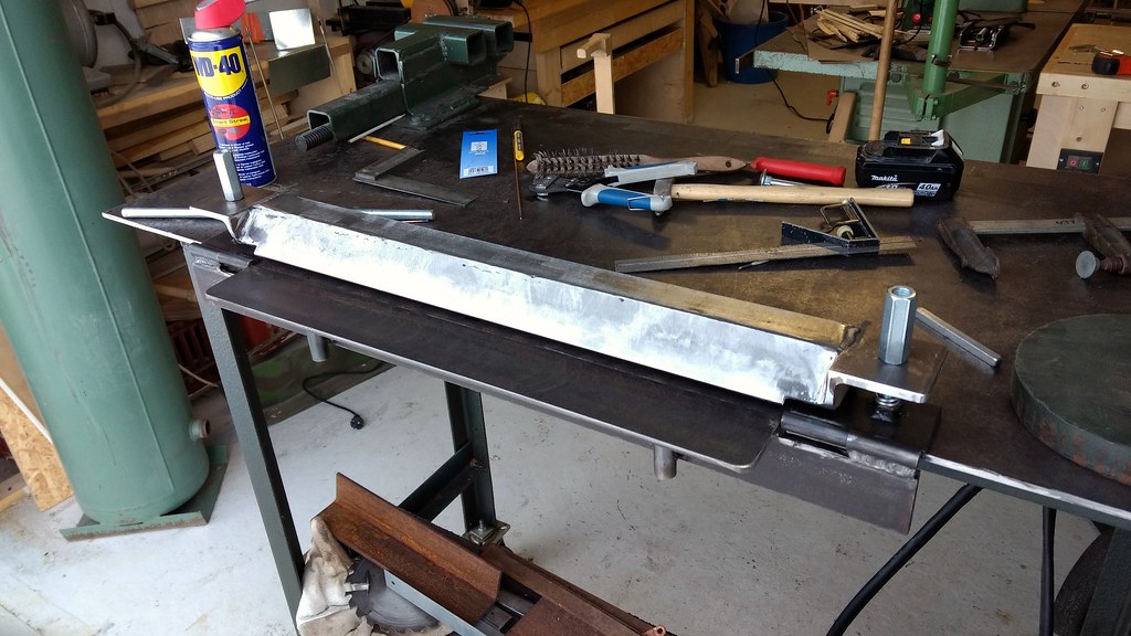 Made a sheet metal brake
|
|
#
?
Mar 12, 2017 17:29
|
|
|
His Divine Shadow posted:
That's pretty cool, did you also make that vise and the bench?
|
|
#
?
Mar 12, 2017 18:14
|
|


|
Pagan posted:Anyone have any good tips or resources on silver soldering? I've run into a wall, and I simply can not get it to work. I'm using copper, and I've tried everything from plumbers solder to easy, medium, and hard silver solder. I clean my pieces, I pickle them... And then the solder just sits there and burns, or it skates off the surface like water on a hot skillet. https://www.youtube.com/watch?v=kIKQ-FL96uU This guy seems to do a lot of it and it looks pretty reliable. My father used to do a bunch and I remember him doing it with a propane torch a shitload of flux and matching wire. It seems that getting the flux that matches your solder is the most important part in getting it to flow.
|
|
#
?
Mar 12, 2017 18:45
|
|

|
Slung Blade posted:That's pretty cool, did you also make that vise and the bench? Yeah almost everything is made from scrap I dug out at the scrap yard or other junk I found, though the brake was made mostly from new stuff.
|
|
#
?
Mar 12, 2017 20:23
|
|
|
Anyone here used these? Saw Jody using it in a video and it looks interesting, I lack a die grinder and electric ones are expensive AF here: http://www.flapperadapter.com/ Air driven ones are cheaper but I dunno if I got the capacity, I got a 25L tank now on a 30 year old compressor, will add a 96l tank and get like 120l total later (like 32 gallons). Maybe it's enough to run such a tool. I dunno...
|
|
#
?
Mar 14, 2017 08:56
|
|
|
What kind of tools would you be likely to use with it? I wouldn't find a spindle like that super useful because I'd want to be able to bring the flapwheel or whatever to the work instead of vice-versa, if I'm working on big steel stuff anyways. I also wouldn't rule air tools out, if you're not doing production work and aren't working with some ludicrously low duty cycle on the compressor it ought to be workable, you might just have to give your compressor time to catch its breath periodically.
|
|
#
?
Mar 14, 2017 14:31
|
|
|
Pagan posted:Anyone have any good tips or resources on silver soldering? I've run into a wall, and I simply can not get it to work. I'm using copper, and I've tried everything from plumbers solder to easy, medium, and hard silver solder. I clean my pieces, I pickle them... And then the solder just sits there and burns, or it skates off the surface like water on a hot skillet. It sounds like your issue is heat control. When I've gotten results like that it's usually because I've 1) melted the solder with the torch instead of letting the part's heat melt the solder, 2) overheated the part and cooked the flux off, or 3) failed to control the heat to take advantage of how solder aggressively flows towards heat if at all possible. Silver soldering in particular is also intended to be done on tight-fitting joints where capillary action does most of the work, it's not like soft solder where you can easily fill gaps and stuff. Solder-flux match is important insofar as you want a flux that only becomes active near the solder's melting point, so it doesn't cook off and stop working before you make the join (or fail to work properly at all because it melts too high), but tbh I've made mechanically-successful if often sloppy joins with several types of silver-bearing/hard solders all with a generic flux intended for low-melting silver solder (the stuff a notch up from easy-flo), so that part isn't insurmountable. If you're soldering at the lowest practicable temperature and that heat is in the work instead of the flame and your flux game is on point, the solder will melt and then zzzzip right into the joint the moment it liquefies and wets to the metal.
|
|
#
?
Mar 14, 2017 14:47
|
|
|
Ambrose Burnside posted:What kind of tools would you be likely to use with it? I wouldn't find a spindle like that super useful because I'd want to be able to bring the flapwheel or whatever to the work instead of vice-versa, if I'm working on big steel stuff anyways. Well I'd want it for grinding away a failed weld inside a corner where it just wasn't possible for me to get at it with an angle grinders disc. A straight die grinder would the tool of choice here but an electric version is $$$. quote:I also wouldn't rule air tools out, if you're not doing production work and aren't working with some ludicrously low duty cycle on the compressor it ought to be workable, you might just have to give your compressor time to catch its breath periodically. It's an old old compressor, but it's held up well, rated something like 48/gallons a minute. I want to upgrade it in the future when I find a good deal.
|
|
#
?
Mar 14, 2017 14:55
|
|
|
Yooper posted:Our rule is everytime the decimal point on the tolerance shifts right, the price adds another digit to the left. Thanks, in absence of any other specs to ask for I'll just ask that I can "work to 0.005" on the parts I'm making. I think I'd like to ask for 0.001" though on parts the width of the table (7"). Another person I asked said to ensure the table is at most +/- 0.003 and spindle runout under 0.002" - i.e. this is what to expect. Possibly buying tomorrow or the next day.... very excited... I've also discovered "Old Tony's" channel on youtube which is amazing to watch for a beginner such as myself - https://www.youtube.com/watch?v=Cw7Mwd6ey6g. He also makes a DIY aluminium / wood router, which is one project I'd really like to do with the assistance of my new machine. edit: Discovered my local supplier sells what looks to be like a Rong Fu 45 clone - http://www.machineryhouse.com.au/M123 - promising? Mudfly fucked around with this message at 15:16 on Mar 18, 2017 |
|
#
?
Mar 16, 2017 20:53
|
|
|
I know you guys have talked about Forged in Fire occasionally, so if you're in the DC area this weekend here's a chance to see the recent winner make something pointy: http://nova.makerfaire.com/maker/entry/216/ Disclaimer: I'm helping run another, unrelated table elsewhere at the event.
|
|
#
?
Mar 17, 2017 04:09
|
|

|
Now that I have gotten my CK torch I have actually started using my pedal and I think it's too easy to start, sometimes I might just nudge the pedal wrongly and the torch starts, I really got the switch tuned so it starts at once. And I don't want to change the overall resistance either, it's just fine as is. I'd just want the initial resistance to be high, then it'd just let go once the pressure was enough to actuate. I know there are mechanisms like this, the mechanical cherry MX keyboard switches come to mind, typing this at a blue MX keyboard... I wonder how one would go about making something like that on a larger scale for a tig pedal...
|
|
#
?
Mar 18, 2017 21:03
|
|
|
Ball mill a radiused dent on the side of the pedal and mount a spring detent pin against it so you have to overcome that force before it starts moving, then it'll stay broken off until you release all the way E: would probably work better on the inside of the pedal that way you have some frame to mount the pin to shame on an IGA fucked around with this message at 22:31 on Mar 18, 2017 |
|
#
?
Mar 18, 2017 22:28
|
|

|
That sounds like a good idea, putting on the inside would be best, probably at the back to prevent the back from lifting as you depress the pedal.
|
|
#
?
Mar 19, 2017 08:33
|
|
|
In my nerve wracking buying a mill experience I've read one of the mills I'm looking at can only go up to 1600rpm. Could this be an issue milling aluminium? Smaller model/robot/3dprinter parts and the like? Makes deciding easier if true... Unless of course there's no way to speed it up, which there probably is.
|
|
#
?
Mar 20, 2017 11:37
|
|
|
Mudfly posted:In my nerve wracking buying a mill experience I've read one of the mills I'm looking at can only go up to 1600rpm. Could this be an issue milling aluminium? Smaller model/robot/3dprinter parts and the like? There are some ways to speed up a spindle. They range from altering your pulleys, adding a gear drive unit, all the way up to installing a VFD and over-hz'ing the spindle. They all suck. I've installed VFD's on machines and people have used them to overspeed the spindles. Electrically it works, but mechanically the spindle bearings aren't rated. Sure you can drive the spindle at 120 Hz (7500 rpm), but it'll overheat and possibly arc in the motor bearings. It's likely not going to be an issue for you. You'll just have to slow down your feeds accordingly. An 1/8" end mill wants 9200 rpm at 300 sfm, 1/2" @ 2200 rpm, 3/4" @ 1500 rpm.
|
|
#
?
Mar 20, 2017 12:34
|
|
|
Mudfly posted:In my nerve wracking buying a mill experience I've read one of the mills I'm looking at can only go up to 1600rpm. Could this be an issue milling aluminium? Smaller model/robot/3dprinter parts and the like? What are your other options max rpm? It won't make it impossible, it'll just slow you down like yooper said. What size tooling do you think you'll use most? The smaller the tooling the more rpm you'll want.
|
|
#
?
Mar 20, 2017 13:31
|
|
|
Thanks, I studied the formulas on chip load and stuff and I think I get it. I have to feed it slowly if I'm limited to 1600rpm, and the feed rate goes up linearly with max rpm. I'd be more worried if I HAD to feed it really quickly for fine work. I can't imagine doing really intricate stuff too often, so I don't think it will bother me. I might just go after the 1600rpm mill now as it's 300kg compared to the other 200kg unit, and mass is a major determining factor in rigidity. I'll email the place tomorrow to see if they can match 0.0015" end to end and 0.0002" front to back on the bed for tolerances, then hand over my cash..... And find a friend with a ute and a crane. edit, to above post: Not sure on tooling but the for smaller 3d printer parts I intend to make initially they're under 5" square so I doubt going slow will bother me. The larger parts I have in mind will mainly involve surface finishes and accurate drilling. Another mill I'm looking at is 2500rpm max, but brushed motor, 200kg, german design chinese made (Optimum) and +$300. 1600rpm unit is 300kg, Chinese RF45 clone. Mudfly fucked around with this message at 14:25 on Mar 20, 2017 |
|
#
?
Mar 20, 2017 14:18
|
|
|

|
| # ? May 26, 2024 22:55 |
|
|
Hey metalworking thread, I normally hang out in the electronics thread but I've been kicking around the idea of building a DIY CNC drill and that'll require some rigid metal parts. Right now, my biggest issue is a baseplate: I'd like a big, heavy, solid plate to bolt all the parts to so they can use it as a dimensionally stable reference. I bought a big ol' 2' x 2' 16GA steel sheet at home depot which seems pretty solid, but when I got it home I realized it has a slight curve to it. Would I be able to adequately correct this by bolting some aluminum 1" square tube across the bottom (since I already have that)? Is there a better way? I was thinking of using wood to brace it since it's cheap and I can get big chunks of it but I'm worried about humidity changes warping the whole thing. Should I abandon the steel sheet altogether and go with something else? My other thought was that I have an old rackmount server case that has a big heavy steel lid that's very flat and incredibly hard to bend, but it's got some bits sticking out where things mounted to it that I'd have to cut off, and it's got a ridge around the outside that I'd probably need to do something about. Relevant tools I have: - Drill bits that can cut metal - A drill - A bunch of different kinds of files - A centerpunch - Sheet metal shears - A smallish rubberized hammer that isn't very useful - One of the nicer Dremel tools with cut-off wheel and grinder wheel and some other bits - Safety equipment / face shield / gloves / ear protection / etc. I'm open to getting other tools too if I'd need them for something. Anyway thanks in advance 
|
|
#
?
Mar 20, 2017 18:58
|
|

