


|
My travel meter is a BK. It's fine, and good for kicking around on deck.
|
 #
?
Aug 8, 2017 14:54
#
?
Aug 8, 2017 14:54
|
|


|

|
| # ? May 18, 2024 22:21 |
|
|
I've used this... thing for literally a decade at least TBF I wasn't really into electronics and this was cheap, tiny, and worked perfectly adequately for measuring batteries, checking continuity for broken connections etc. It was also still useful when I got into RC flying since I could keep it in a pocket in case I needed to check something in the field. Sadly it is no more, after changing the battery and re-soldering the leads (they're fixed) it just doesn't work right and throws all kinds of random numbers. So far I got one of the cheapo Aneng meters as a stop-gap solution since they seemed to get decent reviews. I was planning on picking up a Fluke when I'm in the US in Sept/Oct but it seems that the cheaper ones aren't well suited for electronics and I'm not paying $500 for the right one, no matter how great it is. Anyway, I'm now messing around with a WS2812 strip and while it's pretty much the simplest project I've done recently, but instead I'm completely stuck. I hooked up the strip directly to external power (it can draw up to 2 amps) and the common ground with both a Digispark and Nano, DIN to a digital pin and... it does nothing. I tried a bunch of libraries but couldn't get it to do anything at all, going from scratch or with provided examples. It quickly flashes whenever I connect the power so it's not completely dead, but other than that I can't think of anything I could check without a scope. Are there any common issues with these setups?
|
|
#
?
Aug 8, 2017 21:07
|
|

|
mobby_6kl posted:It quickly flashes whenever I connect the power so it's not completely dead, but other than that I can't think of anything I could check without a scope. Are there any common issues with these setups? You're running at the wrong voltage. Supply voltage and data voltage can differ. It may want 5 or even 12VDC for power and 3.3 or 5v for data. If it's 5V/5V and you're running either with 3.3V, it won't work.
|
|
#
?
Aug 8, 2017 21:44
|
|

|
mobby_6kl posted:I was planning on picking up a Fluke when I'm in the US in Sept/Oct but it seems that the cheaper ones aren't well suited for electronics and I'm not paying $500 for the right one, no matter how great it is. I got this guy a little while back as my main meter: https://www.amazon.com/Greenlee-DM-210A-Multimeter-Operation-Non-Contact/dp/B003TO5YTQ/ As far as I can tell all the Greenlee meters (or at least this one and the 500 series ones) are just rebadged Brymen meters in different colors
|
|
#
?
Aug 9, 2017 00:30
|
|


|
On meter chat, would this Klein be a good one? I don't do anything particularly in depth, mostly just checking DC voltage level +/- 0.1v, if household AC is getting to a socket right, resistance, and continuity. https://www.amazon.com/Klein-Tools-..._36%3A4000-8000 I apparently have banged around my cheapie one from Lowes too much and while the meter still works the select button doesn't so I can't get at some of the stuff I need to anymore. 
|
|
#
?
Aug 9, 2017 00:30
|
|

|
If you're not doing poo poo above 240vac, almost anything will work. The catch is to just be careful of auto-ranging, and make sure you're on the right measurement before you start poking things. Also, don't do electrical work live. turn the breaker off.
|
|
#
?
Aug 9, 2017 00:48
|
|

|
Oh yeah definitely. Only live AC stuff I ever do is checking outlets.
|
|
#
?
Aug 9, 2017 03:00
|
|
|
The Non-contact Voltage Detector feature on the EX330 is really handy and saved my rear end once already back when I was replacing a closet light switch. The switch was in the master bedroom so I shut off the breaker to that room, turns out all the upstairs lighting is on a seperate breaker and the switch was still live. The detector was sensitive enough to detect this without even taking the switch cover off. I realize that there are cheap voltage detector pens and other such tools specifically for this purpose but I almost never work with A/C and haven't found the need to pick one up. DethMarine21 fucked around with this message at 05:47 on Aug 9, 2017 |
|
#
?
Aug 9, 2017 05:44
|
|
|
babyeatingpsychopath posted:You're running at the wrong voltage. Supply voltage and data voltage can differ. It may want 5 or even 12VDC for power and 3.3 or 5v for data. If it's 5V/5V and you're running either with 3.3V, it won't work. This is a good point as I didn't check the logic voltage and just assumed it would be 5V, but according to the data sheet it seems like it it's 0.7VCC high and 0.3VCC low so with 5V input it should also work with the 5V ATMEGA/ATTiny. But I'll double check all the levels just in case.
|
|
#
?
Aug 9, 2017 09:00
|
|
|
Do optical rotary encoders bounce? Every debounce circuit I've found for rotary encoders looks like it'd interfere with the pull up resistors recommended by the manufacturer of an encoder I'm looking at.
|
|
#
?
Aug 9, 2017 20:30
|
|
|
poeticoddity posted:Do optical rotary encoders bounce? Every debounce circuit I've found for rotary encoders looks like it'd interfere with the pull up resistors recommended by the manufacturer of an encoder I'm looking at. What kind of encoder? The Omron 400-pulse (or higher) industrial-style ones, or the little $2 Arduino line-bot ones? I haven't used one yet--but I'm told that the Omron (and similar) encoders have a comparator circuit built-in, so they don't bounce.
|
|
#
?
Aug 11, 2017 18:54
|
|
|
The encoders I have used (industrial stuff with rs-422 output, ~$20-200) haven't needed any debouncing. For cheap ones I'd check the output with a scope and see how it looks before committing to a circuit design.
|
|
#
?
Aug 11, 2017 19:19
|
|


|
The encoders I've been looking at are the $15-30 ones on Digikey that are generally meant for use with a knob in applications where a potentiometer won't work. They're quadrature output and have 32 pulses per revolution. I was able to dig up a bit more and it looks like I shouldn't need debouncing circuitry like I did with mechanical ones. The data sheets had me a bit confused at first but eventually I figured out that the bounce specs were just for the pushbutton function, since they were absent in datasheets for encoders without pushbuttons. Thanks for the tips. If my circuit acts up, I'll scope it out.
|
|
#
?
Aug 11, 2017 20:22
|
|
|
poeticoddity posted:The encoders I've been looking at are the $15-30 ones on Digikey that are generally meant for use with a knob in applications where a potentiometer won't work. They're quadrature output and have 32 pulses per revolution. Post your results, I'd be interested to hear about it. Last time I used a mechanical rotary encoder debouncing it in software was a huge pain in the arse, so if there's a better alternative I'm all ears.
|
|
#
?
Aug 11, 2017 23:26
|
|

|
I've found that 0.1uf caps between the signal pins and ground works really well and is fairly simple to implement.
|
|
#
?
Aug 12, 2017 00:55
|
|

|
Splode posted:Post your results, I'd be interested to hear about it. Last time I used a mechanical rotary encoder debouncing it in software was a huge pain in the arse, so if there's a better alternative I'm all ears. Will do. I'm curious, too. A software debounce of sorts is likely still worthwhile for anything human-operated if you're trying to avoid people spinning knobs or anything. When I first tried a mechanical encoder for user input, I made the mistake of getting one without detents, which meant that if it was left in just the right position it would would bounce at high frequency until you moved it. rawrr posted:I've found that 0.1uf caps between the signal pins and ground works really well and is fairly simple to implement. I've had good results with this circuit before, but it still warrants a bit of software debounce in my experience: 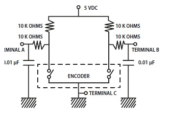
|
|
#
?
Aug 12, 2017 02:07
|
|
|
isn't a debouncer just a low pass filter? just do one of them.
|
|
#
?
Aug 12, 2017 03:55
|
|

|
Malcolm XML posted:isn't a debouncer just a low pass filter? just do one of them. The question is "for what frequency should I design my low-pass filter?" The one in the picture looks like about 1.5kHz cutoff. Is that too high? Too low? Dunno.
|
|
#
?
Aug 12, 2017 14:04
|
|
|
Splode posted:Post your results, I'd be interested to hear about it. Last time I used a mechanical rotary encoder debouncing it in software was a huge pain in the arse, so if there's a better alternative I'm all ears. I have used the PDN2008 chips from PaladinSemi-- https://www.paladinsemi.com/pushbutton_interface.php on the top menu bar on that page,,,,,,, go to [integrated circuits] and then [pushbutton interface] I think I got these from Newark, but they don't list them now. other Google pages mention another debounce chip (that appears very similar) named "ECE2008", but I can't find who makes it or where to get that. So maybe the "2008" designation is for debounce chips...? If you are running the button inputs into (or through) a microprocessor anyway, software debouncing is easier IMO. Just a few lines of software can debounce dozens of different inputs. Or you can have multiple debounce timers for different lengths of time, for different buttons--and neither of the groups' debounce timers will interfere with any of the others. I bought the chips I did because I was starting out with Arduinos and it seemed a convenient luxury. Wiring them up turned out to be more trouble than they're worth IMO. my arduino/pastebin example is here: https://pastebin.com/AzyGz6rp
|
|
#
?
Aug 12, 2017 17:35
|
|
|
Anyone have a favorite battery checker for AA / AAA etc. that they would recommend? I'd like to use it for both alkaline and rechargeable NiMH chemistries.
|
|
#
?
Aug 12, 2017 17:40
|
|


|
peepsalot posted:Anyone have a favorite battery checker for AA / AAA etc. that they would recommend? I'd like to use it for both alkaline and rechargeable NiMH chemistries. "BUY ANYTHING GET THIS METER FREE" Harbor Freight moving-coil analog meter. Use a marker to draw lines on the voltage scale at 1.2, 1.4, 1.5, etc. voltages. The moving coil really helps you determine if the battery is showing surface charge, as the voltage will sag noticeably on a dead cell, even if digital testers show it as good.
|
|
#
?
Aug 12, 2017 18:58
|
|
|
I want to wind a huge electromagnet, going by the plans here: http://www.aaybee.com.au/Magnabend/Building%20Your%20Own%20Magnabend.html Based on his formula, to make a 1000mm long e-typ e magnet I'd need to go up from 20AWG (.8mm) to 19AWG (.9mm) wire and I'd need 821 meters of wire. Now the problem is I can't find long enough wire. Well Ok I've found some silly big spools like 20kg, but I need maybe 5-6kg total. So can I splice magnet wire, is it a commonly done thing or something to be avoided if possible? I assume splicing would be soldering and shrink tape.
|
|
#
?
Aug 16, 2017 12:18
|
|

|
His Divine Shadow posted:I want to wind a huge electromagnet, going by the plans here: Whenever I've wound coils I try to avoid it for practical reasons since it'll mess up the shape of the coil and adds a fragile point that might rub against / erode the insulation on the other loops, but I doubt that would matter much here for something this big. You'd probably be fine, as long as it doesn't get hot enough to melt the heatshrink etc. Anyway thread, does anyone have a suggestion on where to buy pre-made / get optical interrupter encoder wheels made? I tried printing some on a transparency sheet with a laser printer but the toner has enough patchy holes it's not really giving me acceptable output, plus the transparency sheet isn't very stiff (and when I tried gluing two sheets together it just warped and dissolved the toner)
|
|
#
?
Aug 17, 2017 20:13
|
|
|
Aliexpress has some BTW, depending on your application a rotary hall effect sensor like the AS5600 or AS5601 may be easier to implement mechanically.
|
|
#
?
Aug 17, 2017 20:31
|
|
|
ate all the Oreos posted:Anyway thread, does anyone have a suggestion on where to buy pre-made / get optical interrupter encoder wheels made? I tried printing some on a transparency sheet with a laser printer but the toner has enough patchy holes it's not really giving me acceptable output, plus the transparency sheet isn't very stiff (and when I tried gluing two sheets together it just warped and dissolved the toner) http://www.ebay.com/itm/DC-motor-With-AB-Phase-Encoding-Encoder-334-Lines-/252583268555 I was blown away by the precision vs cost ratio on this thing compared to other stuff I was finding. It didn't occur to me that encoder + motor might actually be cheaper than buying an encoder on its own, but that seems to be the case here. Also that motor is a pretty dinky toy, but i think its feasible to retrofit the encoder to a larger motor.
|
|
#
?
Aug 17, 2017 21:53
|
|
|
ate all the Oreos posted:Anyway thread, does anyone have a suggestion on where to buy pre-made / get optical interrupter encoder wheels made? I tried printing some on a transparency sheet with a laser printer but the toner has enough patchy holes it's not really giving me acceptable output, plus the transparency sheet isn't very stiff (and when I tried gluing two sheets together it just warped and dissolved the toner) I dunno what sort of sensor you're using / if you need a gray code wheel / what sort of resolution / etc. but I have had good luck making moderately-sized slotwheels (about 2" across) with a 3D printer.
|
|
#
?
Aug 18, 2017 02:29
|
|


|
Okay fun RF question that's been bugging me. See the following image: http://imgur.com/a/qHPjn I have a parallel plate capacitor driven at some frequency. Between the plates there are three thin conductors with the electrical lengths shown (consider these as three different scenarios - the conductors don't actually "see" each other). Assume the plates of the capacitor are far away from the conductors and the field is uniform. Question: what is the current distribution along each of the conductors? This is really tripping me up for some reason. Typically, the boundary condition imposed is that the current goes to zero at the end points. So, for example, for the quarter-wavelength conductor, that would mean you have two current nodes. But, as its a quarter-wavelength, it "should" have a node at one end and anti-node at the other. Basically, I'm having trouble squaring these two assumptions about the physics of the situation. Any help here would be most appreciated!
|
|
#
?
Aug 18, 2017 04:25
|
|

|
Hey guys, I'm trying to IoT my air purifier. It has a dumb control scheme where I can't program hours I'd like it to run, I can only turn it on and tell it to run for X hours at which point it just shuts off end of story. The control plane is just a set of membrane switches. My goal is to throw an esp8266 behind there to allow for some automation so I can set the ESP as a dumb endpoint and have a python script somewhere else tell the time and when I'm supposed to be at work to let that thing crank at full blast until I'm supposed to get home. I'm thinking the easiest way to get/set state is just to read the state of LEDs on the control plane and emulate push buttons based on what the LEDs are displaying. Any thoughts on how to accomplish that in a safe way? I'm picturing something like optoisolating everything, reading the state of LEDs into shift registers then running through logic based on what's displayed and simulating some push buttons through .. more optos? I'm old hat at programming but I'm garbo at the electronics side of things. Lots of to learn for sure, but I don't think it's too over my head as a beginner project. I just want to make sure I'm not frying things. Suggestions appreciated?
|
|
#
?
Aug 18, 2017 18:30
|
|


|
Martytoof posted:Hey guys, The air purifier's control circuitry is probably just internally operating some kind of on/off switch right? If you don't care about operating it manually (or want to add some buttons to your project) I'd just rip out the entire existing control system and replace it with a relay driven by your esp8266
|
|
#
?
Aug 18, 2017 18:38
|
|
|
Putting optos in parallel with switches is how I've done similar things before. Easy, worked well, and isolated. It can fail with some uncommon multiplexing schemes though. Be sure to check polarity. 2 color (usually green / red) 2 lead LEDs can mess you up here, as they are in reverse parallel. They aren't too common on modern things though. The good news is that they are still easy to interface with. You just need 2 optos in reverse parallel. Also optos have a much lower voltage drop than visible LEDs, so if you just wire them in parallel with the existing LED and share its resistor, you'll effectively short out the visible one. Multiplexing can also cause issues here, as only one indicator is actually on at a time. PWM can also cause issues as you may not be looking at the light when it's on. If either of those is an issue, a low pass filter on each shift register input would fix it, though my preference would be a i2 gpio input with an on change interrupt pin, and then a software timeout. A light is really off if it's off now, and hasn't been on in so many milliseconds. But it will probably just work.
|
|
#
?
Aug 18, 2017 19:04
|
|

|
mobby_6kl posted:So far I got one of the cheapo Aneng meters as a stop-gap solution since they seemed to get decent reviews. I was planning on picking up a Fluke when I'm in the US in Sept/Oct but it seems that the cheaper ones aren't well suited for electronics and I'm not paying $500 for the right one, no matter how great it is.  Well it's not like there's a model that is both 9999 counts and a temp feature though, maybe I'll just keep both... Also got a cheap-rear end USB soldering iron which actually works surprisingly well and I think could be useful for fixing up my plane and drones in the field: https://www.youtube.com/watch?v=o-8D5t6TJYU babyeatingpsychopath posted:You're running at the wrong voltage. Supply voltage and data voltage can differ. It may want 5 or even 12VDC for power and 3.3 or 5v for data. If it's 5V/5V and you're running either with 3.3V, it won't work. 
|
|
#
?
Aug 18, 2017 20:01
|
|
|
Martytoof posted:I'm old hat at programming but I'm garbo at the electronics side of things. Lots of to learn for sure, but I don't think it's too over my head as a beginner project. I just want to make sure I'm not frying things. Suggestions appreciated? Just checking that the whole point is to integrate into the existing electronics, right? There's IoT air purifiers out there, and if the thing will turn on full blast when plugged in a IoT relay on the socket would be enough.
|
|
#
?
Aug 18, 2017 20:09
|
|

|
Cyril Sneer posted:Okay fun RF question that's been bugging me. See the following image: I dont know but I am very curious now. if you dont get an answer here maybe try the engineering thread in BFC: https://forums.somethingawful.com/showthread.php?threadid=3209369
|
|
#
?
Aug 18, 2017 20:22
|
|

|
ate all the Oreos posted:The air purifier's control circuitry is probably just internally operating some kind of on/off switch right? If you don't care about operating it manually (or want to add some buttons to your project) I'd just rip out the entire existing control system and replace it with a relay driven by your esp8266 Not a terrible idea but I'm hoping to retain the working user interface elements and just drive it via esp if I can't manually push a button.  Not /exactly/ as pictured but close enough. It sounds like I'll give it a go with the optos. It ought to be a fun project. Thanks ") JawnV6 posted:Just checking that the whole point is to integrate into the existing electronics, right? There's IoT air purifiers out there, and if the thing will turn on full blast when plugged in a IoT relay on the socket would be enough. Yeah, twofold project. To add iot to the existing hardware and to use the stack of esp's I impulse ordered last year. Unfortunately when you plug this in it sits there doing nothing until you explicitly push the power button. My logic will just be a simple loop to detect LED states to determine current function and then push some buttons until it matches up with desired operating state. Slap an API onto it and maybe integrate it into homebridge so I can control it with my phone. some kinda jackal fucked around with this message at 20:43 on Aug 18, 2017 |
|
#
?
Aug 18, 2017 20:39
|
|
|
Is it the kind that uses electrostatic / "ionizing" air purification? Because if so it probably has a high voltage DC power supply inside and might be a bit dangerous if you've never worked with that sort of thing before.
|
|
#
?
Aug 18, 2017 21:36
|
|
|
ate all the Oreos posted:Is it the kind that uses electrostatic / "ionizing" air purification? Because if so it probably has a high voltage DC power supply inside and might be a bit dangerous if you've never worked with that sort of thing before. It does indeed. I have a base understanding of how to tap the power from the existing circuitry and what not to touch but I'm going to do all the actual work supervised. My father is an EE so I can get his input once it's time to crack everything open.
|
|
#
?
Aug 18, 2017 22:15
|
|
|
I'd open it up and take a ton of pictures (and post them here) before trying to plan a project. For all you know, there will be a couple conspicuously empty header footprints labeled "TURN ON NOW, 3V3"
|
|
#
?
Aug 18, 2017 22:51
|
|

|
ante posted:I'd open it up and take a ton of pictures (and post them here) before trying to plan a project. I'd be happy to involve the thread. I'll grab some shots when I'm back in town.
|
|
#
?
Aug 18, 2017 23:29
|
|
|
Scanned through the last couple of pages and the OP and didn't see this mentioned anywhere: Is the Rigol DS1054Z still a good beginner scope? I know that EEVBlog dude liked it, but that was a while ago I think.
|
|
#
?
Aug 19, 2017 00:46
|
|


|

|
| # ? May 18, 2024 22:21 |
|
|
Yeah, it's still good. Some other companies have started to compete, but the hobbyist community support is still behind the Rigol, which is worth its weight in gold
|
|
#
?
Aug 19, 2017 01:00
|
|