


|
His Divine Shadow posted:So I got this welder with a bum LCD panel. It's a pretty old machine, 1990s era something. I took off the covers tonight to have a closer look at the panel. I'd really like it replaced as its job is to show what amperage I am using. Looks like 7‐segment parallel connection. 0.1″ pin pitch so 2 inches wide? I�m not going to count holes to figure out the height. Here�s a list on Digikey; filter out the ones that are the wrong height (which is listed as �width� for dumb reasons). Don�t get one that takes the wrong voltage or has the wrong number of characters, either. Are you sure the screen is broken, and only the screen? It�s no good to replace it only to find the driver is broken. Platystemon fucked around with this message at 20:20 on Sep 14, 2016 |
 #
?
Sep 14, 2016 20:06
#
?
Sep 14, 2016 20:06
|
|


|

|
| # ? Jun 10, 2024 01:50 |
|
|
I am not sure, but just replacing a part is all I can realistically do. I have no idea how to correct any software, but it sounds like something that if it was screwed up could affect the welders performance, but it seems to operate normally.
|
|
#
?
Sep 14, 2016 20:14
|
|

|
His Divine Shadow posted:So I got this welder with a bum LCD panel. It's a pretty old machine, 1990s era something. I took off the covers tonight to have a closer look at the panel. I'd really like it replaced as its job is to show what amperage I am using. Replacing just the LCD might be tricky--those things aren't particularly standardized, so a drop-in equivalent might not work (and could potentially do further damage to parts, in the worst case scenario). However, the LCD looks like it is socketed (albeit in a strange way, like maybe the manufacturer had to do it because they messed up part height during design). So you might be able to carefully pull off the LCD and look for any specific part numbers on the back. It's also possible that it's not the LCD that's broken, but something else on that logic board (like the LCD driver IC that is peaking out from underneath it, i assume). I'd start with trying to find any schematics for the welder (but it's probably a bit too new for that). Look for any part numbers on that LCD board, because getting a replacement board might be easier than replacing that specific old LCD (or it might not!). If you don't have luck with any of this, then there is a backup solution you might consider--ignore the LCD, and add-on an off-the-shelf industrial current meter. I have no clue how any of this is wired up, or what type of current sensor they are using, or if they are doing anything more complicated (like what if that IC under the LCD is a microcontroller and not an LCD driver, and in fact the current displayed on the LCD is actually some calculated value that compensates for losses due to blah blah blah). But if it's something simple, like current sense resistors with a sense amplifier on the LCD board, then you might be able to wire in a replacement, if the right voltages are present to power an external module. summary: 1. Try to pop the LCD out of it's socket (note- make sure to mark it and the PCB so that you dont reinstall it upside down) and look for a part number on the back 2. Try to look up any schematics that might be available 3. Try to find a replacement for the whole LCD board. 4. Bolt on a industrial current meter and use that as a replacement.(depends on the type of current sensor that is currently used, which you might be able to figure out). Slanderer fucked around with this message at 20:18 on Sep 14, 2016 |
|
#
?
Sep 14, 2016 20:15
|
|
|
Slanderer posted:If you don't have luck with any of this, then there is a backup solution you might consider--ignore the LCD, and add-on an off-the-shelf industrial current meter. I like this Gordian solution, but if it�s a display for the current limit, and not actual current in use, that won�t work. e: The knobs probably tell you the current limit on a �90s unit, though. Hall effect sensors for DC current are available these days if you can�t/don�t want to use a current shunt. Platystemon fucked around with this message at 20:28 on Sep 14, 2016 |
|
#
?
Sep 14, 2016 20:23
|
|
|
The knob is like 0-10 for a 10-300A welding range so it's a bit rough but it's how I am doing it now. I might just take it to the Kemppi service center near me instead. The welder is a bit old but perhaps they can do something about it, they'd take like 30 bucks just to look at it however.
|
|
#
?
Sep 14, 2016 20:28
|
|
|
silence_kit posted:I don't have intimate knowledge of designing these kinds of systems, but have a hunch that what you want may be kind of tricky to design. I think what would happen with a normal FET as a switch is the drain-source capacitance would be large enough that it wouldn't really attenuate at all. The gate-drain/gate-source capacitances would also basically short a power fet out completely at GHz frequencies. PIN switches or RF relays are pretty ok solutions as well as the IC based ones. OP: For a module based solution look for either a coax relay/coax switch, or alternately a transmit/receive switch/relay (T/R relay) and there's probably someone who's selling that at a reasonable price.
|
|
#
?
Sep 14, 2016 23:01
|
|


|
His Divine Shadow, on the off chance you haven't done so already, it looks like your display is mounted (probably soldered) into a pair of pin adapters which are then inserted into sockets on the circuit board, so you could presumably carefully pull it out and see if there's any useful information on the back of the display module.
|
|
#
?
Sep 15, 2016 02:26
|
|
|
I was looking at that too but I don't know for certain so I didn't even try to pull it out. Someone gave me the tip to clean the entire board, with compressed air, then water, soap and a tooth brush and let it dry overnight. All the other boards in the welder look real clean but this one's very dirty, probably dirt gets in around the hole for the LCD. Another tip was to remove the display and clean the contacts with isopropanol. EDIT: I think the correct english translation is Isopropyl alcohol, and I found the local hardware store sells spray cans of it for cleaning electronics. Maybe I should try it firs, or just compressed air. His Divine Shadow fucked around with this message at 06:23 on Sep 15, 2016 |
|
#
?
Sep 15, 2016 04:20
|
|
|
His Divine Shadow posted:I was looking at that too but I don't know for certain so I didn't even try to pull it out. Someone gave me the tip to clean the entire board, with compressed air, then water, soap and a tooth brush and let it dry overnight. All the other boards in the welder look real clean but this one's very dirty, probably dirt gets in around the hole for the LCD. Isopropanol and isopropyl alcohol are the same thing. The former follows the naming standards for organic chemistry and the latter is the name you'll typically see in pharmacies. I would definitely recommend isopropanol over soap and water.
|
|
#
?
Sep 15, 2016 10:58
|
|
|
Took in the card and got the LCD off, it was pretty easy, the chip under it says Maxim ICL7116CPL, which is a display driver. I assume there's some kind of standardized display software on this that is always the same so it can be swapped out? http://www.digikey.com/product-detail/en/maxim-integrated/ICL7116CPL/ICL7116CPL-ND/466065 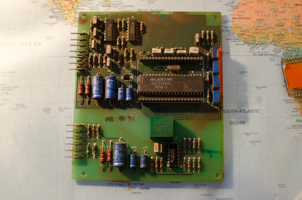
|
|
#
?
Sep 15, 2016 17:20
|
|
|
I'm not sure about the replacement but I can't recommend using soap because it will probably leave a residue. I Alcohol is great though
|
|
#
?
Sep 15, 2016 17:25
|
|

|
His Divine Shadow posted:Took in the card and got the LCD off, it was pretty easy, the chip under it says Maxim ICL7116CPL, which is a display driver. I assume there's some kind of standardized display software on this that is always the same so it can be swapped out? Yeah that means you can probably just find any replacement lcd with enough segments and use the datasheet to hook it up, (assuming its the lcd and not something else of course) e: https://datasheets.maximintegrated.com/en/ds/ICL7116-ICL7117.pdf
|
|
#
?
Sep 15, 2016 17:26
|
|


|
Thanks, I think it might be the display or just the card/connections being dirty. There's a hairline crack on the side of the display (lower right), not sure if affects anything or not: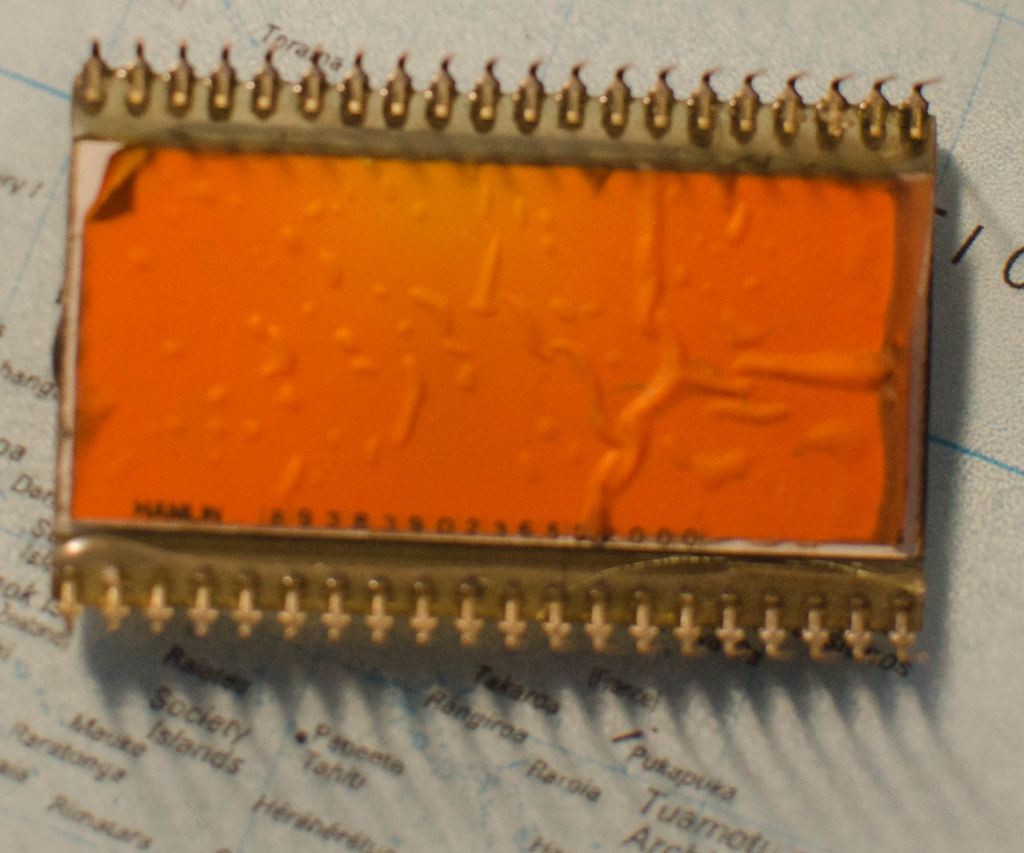
|
|
#
?
Sep 15, 2016 18:14
|
|
|
His Divine Shadow posted:Thanks, I think it might be the display or just the card/connections being dirty. There's a hairline crack on the side of the display (lower right), not sure if affects anything or not: Clean the connectors (and possibly the sockets that the pins were seated into) with rubbing alcohol, let it fully dry, reinsert the display (making sure you have it in its original orientation), and give it a try. If that doesn't work, your next best bet is probably to search for the part number on the back of the display (it's blurry in your photo) and see if you can find a replacement.
|
|
#
?
Sep 15, 2016 23:50
|
|
|
I cleaned the entire PCB and put it back but no go. Same as before. Someone else said the damage on the picture could have the results I am describing, so a new panel would be in order first off.
|
|
#
?
Sep 16, 2016 05:33
|
|
|
If you've got access to a scope, I'd throw one onto the LCD connections to make sure data is being transmitted. You've already checked voltage and ground, right?
|
|
#
?
Sep 16, 2016 10:51
|
|


|
Lol no, can't you see I'm an idiot? I'm not being sarcastic. I don't know electronics. I wouldn't know what the point would be in doing that. I can just try and swap parts for other parts basically.
|
|
#
?
Sep 16, 2016 10:54
|
|
|
His Divine Shadow posted:Lol no, can't you see I'm an idiot? Get a multimeter, and a data sheet. Put the meter on Volts DC of appropriate range, stick the black lead on ground, and the red on the Vcc pin. Read voltage. If you want specific advice, ask away.
|
|
#
?
Sep 16, 2016 18:55
|
|
|
Check, some of the pins to verify that the display driver is working. You can safely probe the sockets while the welder is plugged in, right? Keep the black lead on ground and probe around with the red lead on pins that should be receiving power. Let�s use this for an example:  Say I was expecting a zeroed display. That would mean A�F would be powered on digits 1�3. The digit numbering order isn�t always consistent between LCDs, but the lettering is standardised. On the example LCD, I�d keep the black lead pressed against socket 1 or 40 (both tied to ground) and expect +5 V when I placed the red lead in sockets 9�11, 13�15, 17�22, 24�26, and 29�31. Everything else should be 0 V or thereabouts. Your LCD might have a different pinout or you may not be able to set it to a known value, but finding some pins +5 and some 0 is enough to confirm the LCD is broken and the controller probably works fine. By carefully manipulating the dials and probing the sockets, you could somewhat tediously reverse engineer the pinout for your LCD if you can�t find a datasheet.
|
|
#
?
Sep 16, 2016 20:26
|
|
|
Uh, dudes? That's above the ability of a stark beginner probably. Additionally, those displays require an AC input (+/-5V usually) that won't be very amenable to testing with a multimeter. Guy, can you post lots of hi-res pictures of the board? I'd clean all that rust gunk off it, and then look carefully at the ends of all those blue capacitors for bulging or leaking, and then the D-shaped transistors for scorch marks. Also everything else for scorch marks. Everything on that board should be low-voltage, so plugging it in and checking for things that get hot might be decent, too.
|
|
#
?
Sep 16, 2016 23:41
|
|

|
Personally after taking apart lots of old junk I have never seen an LCD with a crack that wasn't permanently damaged or completely unusable, even small cracks. I'm sure they exist, and it's entirely possible that one of those old-rear end caps could have busted, but ehhhh that crack is really suspicious.
|
|
#
?
Sep 16, 2016 23:45
|
|


|
I wish my friend's welder was even that modern. He's got an old spot welder that's been acting funny. The timing circuit has basically ac mains running through it, vacuum tubes and poo poo. Neither of us have any business messing with that stuff so I convinced him not to even poke around in there.
|
|
#
?
Sep 17, 2016 05:57
|
|

|
darkhand posted:I wish my friend's welder was even that modern. He's got an old spot welder that's been acting funny. The timing circuit has basically ac mains running through it, vacuum tubes and poo poo. Neither of us have any business messing with that stuff so I convinced him not to even poke around in there. Vacuum tubes? How did he even get it, from an antique store?
|
|
#
?
Sep 17, 2016 07:37
|
|
|
Parallel Paraplegic posted:Vacuum tubes? How did he even get it, from an antique store? I've been around some equipment that used silvered tubes. some of it was the control system for some kind of distributed radar system/receiver, I think it was still in use. I was just there to tap into the 3-phase power it supplied edit: they weren't glowing, so not vacuum tubes? I don't really know much about them
|
|
#
?
Sep 17, 2016 07:46
|
|

|
Eh yeah I guess it's not that weird, we really couldn't do high-power switching/amplification (especially of RF like that radar) effectively with transistors until surprisingly recently
|
|
#
?
Sep 17, 2016 07:50
|
|
|
Yeah it's a giant old commercial style spot welder from the '50s. He was specifically trying to recreate old style welds, I guess.
darkhand fucked around with this message at 07:55 on Sep 17, 2016 |
|
#
?
Sep 17, 2016 07:52
|
|
|
Cumslut1895 posted:edit: they weren't glowing, so not vacuum tubes? I don't really know much about them They could have been tubes with silvering around the entire jacket, which you wouldn't be able to see the glow through, or they might have just been old capacitors which I've mistaken for tubes before myself, like this one:  Standing up on a circuit board they look very tube-like from afar.
|
|
#
?
Sep 17, 2016 07:52
|
|
|
Parallel Paraplegic posted:They could have been tubes with silvering around the entire jacket, which you wouldn't be able to see the glow through, or they might have just been old capacitors which I've mistaken for tubes before myself, like this one: they were definitely tubes, there was a shelf of replacements in boxes.
|
|
#
?
Sep 17, 2016 07:53
|
|
|
Parallel Paraplegic posted:Eh yeah I guess it's not that weird, we really couldn't do high-power switching/amplification (especially of RF like that radar) effectively with transistors until surprisingly recently Klystrons are still in use aboard many new satellites. Cavity magnetrons also remain the most cost‐effective solution for microwave ovens.
|
|
#
?
Sep 17, 2016 22:35
|
|
|
Platystemon posted:Klystrons are still in use aboard many new satellites. Yeah my dad (an EE) came over to visit me in my new apartment in Tampa and pointed out that our news channel here is called KLYSTRON 9 because... I guess their weather radar has a klystron in it? and we were loling it up that that was the big killer feature they named the entire TV station after 
|
|
#
?
Sep 17, 2016 22:43
|
|
|
Vacuum channel transistors are a promising area of research. The funny thing is that nowadays transistors can be made so small that 1 bar is a relative vacuum.
|
|
#
?
Sep 17, 2016 23:03
|
|
|
My friend has a stand lamp made from a vacuum tube from a megawatt-level air search radar. The date of manufacture on the outside of the tube is late 90s. I was surprised there were still US companies making tubes, but he just said "it's hard to find an RF transistor that can handle a couple million watts, peak."
|
|
#
?
Sep 17, 2016 23:49
|
|

|
Klystrons are also famously used in nuclear weapons (there are at least a few real-life cases and even movies involving schemes to smuggle them for that purpose) but I don't know if newer designs have obsoleted them or if they're still king poo poo of rapid high-power switching. Transistor-based microwaves are starting to become a thing but it still took like 60 years from commercial availability of transistors for this to become possible and economical, and products of this kind still aren't slated until next year. I expect that one day vacuum tubes will be fully obsolete, but we're not quite there yet. That said it's all moot because darkhand's welder is from the 50s and it took a decade or two from the commercial availability of transistors for them to get to the point where they could replace them in all areas. I have a scope from the 60s that is fully transistorized except for a handful of vacuum tubes that were used because transistors that could match them did not exist at the time. One of them is used in the CRT high voltage circuit as a rectifier and another pair are used to provided high impedance on the input stage. Oddly enough if the latter tubes fail you can take essentially any cheap N-channel JFET and jam it into the mini tube sockets as a perfect replacement.
|
|
#
?
Sep 18, 2016 01:48
|
|
|
I love old poo poo like that, my workshop is filled with old iron tools mainly. This welder is way more modern than most of my other stuff. I've been using it now so it's all bundled up. I am thinking I'll risk the 6 bucks on a replacement standard LCD and see what happens. I mean it's not like it'll explode... right?
|
|
#
?
Sep 18, 2016 07:09
|
|
|
His Divine Shadow posted:I love old poo poo like that, my workshop is filled with old iron tools mainly. This welder is way more modern than most of my other stuff. Your worst case is damaging more of the associated electronics. It probably won't explode, but you may yet end up worse off than you started.
|
|
#
?
Sep 18, 2016 15:21
|
|


|
Stupid question: If I need X amps for a circuit but cannot find a suitable wall-wart PS that fits my needs, can I use 2 half-X amp wall-warts in parallel? I found a PS that has the amperage I want, but I cannot find a matching barrel jack that can handle the amperage. 
|
|
#
?
Sep 18, 2016 19:25
|
|
|
poeticoddity posted:Stupid question: If I need X amps for a circuit but cannot find a suitable wall-wart PS that fits my needs, can I use 2 half-X amp wall-warts in parallel? So you�re going to have one power supply with two barrel coming out of it, going into two sockets on the same device?
|
|
#
?
Sep 18, 2016 19:47
|
|
|
KnifeWrench posted:Your worst case is damaging more of the associated electronics. It probably won't explode, but you may yet end up worse off than you started. No, there's no reason that plugging a new LCD will damage anything else. It does seem like the low hanging fruit in troubleshooting, worth a shot! Worst case scenario, it doesn't work or damages the new LCD. Definitely check for burnt components while you've got the board out again, though. The datasheet for the driver chip lists a couple compatible LCDs that will work. I didn't check to see what the difference is.
|
|
#
?
Sep 18, 2016 20:08
|
|
|
When you say you can't find a barrel jack that can handle the current, alarm bells are ringing in my head. What are you doing and how much current are we talking about?
|
|
#
?
Sep 18, 2016 20:08
|
|

|

|
| # ? Jun 10, 2024 01:50 |
|
|
Platystemon posted:So you�re going to have one power supply with two barrel coming out of it, going into two sockets on the same device? Sagebrush posted:When you say you can't find a barrel jack that can handle the current, alarm bells are ringing in my head. I'm building an LED array for yet another laboratory instrument. In this case, there will be a single controller (where the power is fed in) and up to 4 outgoing lines leading to LEDs and controller circuitry. Everything's running at 5V, and there's not a way to switch to a series connection to up the voltage and drop the amperage. I also cannot run power separate from the outgoing lines I mentioned because of weight and size constraints. Depending on how the equipment will be configured for a given experiment, maximum current draw from the LEDs can be expected to be either 2.4A, 4.8A, or 5.6A. Naturally, I want some padding so the PS isn't running at max output and to account for the draw of the controllers (which should be less than 0.25A). I'm trying to make this device as modular as possible and as easy as I can for future users to replace parts that might get damaged, so I was pretty happy to find a 5V 10A PS with a 2.1mm ID / 5.5mm OD barrel jack that's pretty common for 5V wall warts. Unfortunately, I haven't been able to find a mating socket rated for that amperage, which makes me uneasy. There are, however, a lot of 5V 4A wall warts that fit that same standard barrel jack, and are likely to be available in the future. My thought was to have two matching sockets which are rated for at least 5A (much easier to find) feeding the controller from two identical 4A supplies.
|
|
#
?
Sep 18, 2016 21:01
|
|