


|
Shame Boy posted:I know it's basically a standard and all but "trust the C compiler not to do something stupid" still feels intensely wrong even if I know it's probably fine All signed integers in C are compiler dependent ") The language definition is very careful to avoid requiring 2's complement because there were still computers that did negative integers by one's complement (0x0001 = +1, 0xFFFE = -1, 0x0000 = +0, 0xFFFF = -0) when it was being made. The language definition is very careful to avoid requiring 2's complement because there were still computers that did negative integers by one's complement (0x0001 = +1, 0xFFFE = -1, 0x0000 = +0, 0xFFFF = -0) when it was being made.Better examples for Cyril Sneer now that I'm not phoneposting. (All of this is assuming a compiler and platform made sometime in the last 40 years.) code:Foxfire_ fucked around with this message at 04:45 on Sep 5, 2019 |
 #
?
Sep 5, 2019 04:39
#
?
Sep 5, 2019 04:39
|
|


|

|
| # ? Jun 12, 2024 13:28 |
|
|
babyeatingpsychopath posted:Oddly enough, your specific device is called an "automotive relay." 12V coil, switches 12V loads. Head on down to your local car parts store and get a relay and a relay base and go to town. I like the license plate light for a switch source. That's pretty clever. KnifeWrench posted:You seem to be on the right track to me. A relay seems like an elegant way to do what you need, and license plate illumination seems like a low risk circuit to touch. I'd double check what those lights are drawing to make sure you have the headroom to run the relay, and if you have the means, scope out what the voltage looks like on startup (wiring a relay straight in with no debouncing might shorten its life if the coil voltage isn't clean). Thanks for the feedback! Going to run with automotive relay and borrow a DSO to check the voltage on startup. Appreciate the help!
|
|
#
?
Sep 5, 2019 12:40
|
|


|
Foxfire_ posted:There are two different kinds of right shifts, arithmetic and logical. The ADC itself probably doesn't, but its part of an IC for audio processing and interfaces with the MCU via the I2S but interface. All these replies have been interesting, but ugggh, I had no idea there were all these little subtleties. As you can see, I'm not an embedded guy.
|
|
#
?
Sep 5, 2019 13:11
|
|

|
Don't get discouraged! If I'm understanding what you are trying to do, all you need is to just divide each sample by 8 (either with a / or a >>, there's no difference). The rest is just details about how signed integers are stored, which isn't obvious (and took awhile for people to figure out and design). Then, to possibly discourage you, are you measuring audio? Doing a 16 -> 8 bit conversation like this is probably going to introduce audible distortion. Human hearing is very good at detecting small frequency changes and always rounding towards zero will be noticeable. There's a bunch of more complicated noise whitening methods to avoid introducing audible changes
|
|
#
?
Sep 5, 2019 17:30
|
|
|
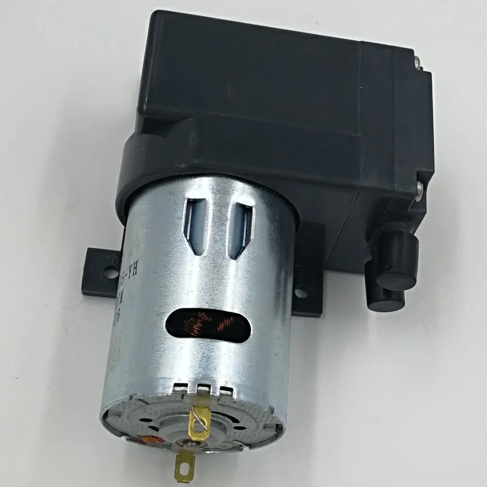
isn't really an electronics question except "yeah its powered by electricity" but idk where else to ask: i'm trying to find an air compressor/pump that'll fit a project; I want the cheapest/smallest solution that only needs to supply ~10-15 lpm at 20 psi, but with a 100% duty cycle; it must be fairly quiet; and the air intake draw rate will never fluctuate, so a storage air tank isn't necessary and ideally can be omitted. oil free design also preferable. 12v automotive compressors supply more than enough air at a far higher pressure than i need and are cheap, but they're noisy and have duty cycles of "don't do two tires in a row". Small portable compressors with storage tanks of a couple gallons are likely workable, but huge overkill in terms of pressure while lacking in supply, and are too big to actually integrate directly into the project, which would be ideal. 20psi seems like an awkward zone b/c almost everybody wants a lot more pressure and less flow from a 'compressor', yet small pumps with modest flow are rarely called on to pressurize anything.
|
|
#
?
Sep 5, 2019 17:42
|
|

|
Ambrose Burnside posted:isn't really an electronics question except "yeah its powered by electricity" but idk where else to ask: Check out a micro HVLP system? You want the volume and not the pressure, so maybe there's a solution ready-made. Dental compressor? Airbrush compressor? Tire compressors certainly aren't going to work.
|
|
#
?
Sep 5, 2019 18:18
|
|


|
Yeah I'd say try an airbrush compressor. Here's the cheaper(airbrush not included) harbor freight kit: https://www.harborfreight.com/1-6-hp-40-psi-oilless-airbrush-compressor-93657.html Its rated for 0.5CFM @ 20psi, so pretty much exactly what you want. ...although no idea about the duty cycle on that. Maybe add a decent case fan to the cylinder head just to be safe(it says it has thermal protection so will shut itself off if too hot).
|
|
#
?
Sep 5, 2019 18:25
|
|


|
Ambrose Burnside posted:isn't really an electronics question except "yeah its powered by electricity" but idk where else to ask: We use this in robotics for pneumatic stuff. Converting units, it looks like ~12 lpm at 20 psi and runs fine for at least several minutes straight (never left it longer). Never oiled it either. Hard to characterize noise level, but I'd say you can have a conversation near it with elevated voices (but not shouting).
|
|
#
?
Sep 5, 2019 19:33
|
|

|
Ambrose Burnside posted:isn't really an electronics question except "yeah its powered by electricity" but idk where else to ask: Just curious what's the project? Sorta sounds like a 3d printer nozzle-cooler.
|
|
#
?
Sep 5, 2019 19:54
|
|
|
think i found a p close fit: Ambrose Burnside posted:i went looking specifically for "chinese b2b-oriented pump sellers" who ostensibly supply all the different small DC pumps for various other products and think i hit the jackpot: insta posted:Just curious what's the project? Sorta sounds like a 3d printer nozzle-cooler.
|
|
#
?
Sep 5, 2019 20:04
|
|
|
Stabby McDamage posted:We use this in robotics for pneumatic stuff. Converting units, it looks like ~12 lpm at 20 psi and runs fine for at least several minutes straight (never left it longer). Never oiled it either. Hard to characterize noise level, but I'd say you can have a conversation near it with elevated voices (but not shouting). That Viaair 090 is rated at 9% duty cycle at 100psi. The 250IG is the smallest continuous duty Viaair. sharkytm fucked around with this message at 01:18 on Sep 6, 2019 |
|
#
?
Sep 6, 2019 01:15
|
|
|
I'm fixing an old tube-based signal generator and I keep getting shocked. I'm measuring 60 volts AC from the metal frame to a ground prong at an outlet. I'm trying to understand it and I just can't. The only transformer puts out 120 volts and 6.3 volts with its respective windings. I pulled all the tubes and still it's hot to the case. How can I be getting an AC voltage the transformer doesn't put out? Internal short in the transformer?
kid sinister fucked around with this message at 01:18 on Sep 8, 2019 |
|
#
?
Sep 8, 2019 01:14
|
|
|
You're measuring a voltage divider
|
|
#
?
Sep 8, 2019 01:19
|
|

|
Well I just unhooked everything but the 2 filter caps attached to either side of the power cord (line to ground) and I'm still getting shocked when I touch the case. Still 60 volts AC. Is this thing that unsafe?
|
|
#
?
Sep 8, 2019 04:15
|
|
|
Is it actually a three-pin plug? Some old stuff "grounded" the case by connecting it to the neutral prong, and then made this even more fun by not using a polarized plug so you could plug the neutral into the hot.
|
|
#
?
Sep 8, 2019 04:16
|
|


|
kid sinister posted:Well I just unhooked everything but the 2 filter caps attached to either side of the power cord (line to ground) and I'm still getting shocked when I touch the case. Still 60 volts AC. Is this thing that unsafe? Sounds like you got some leaky caps there then  What kind of caps are they? Maybe take a picture if you can't identify them and we'll take a shot.
|
|
#
?
Sep 8, 2019 04:17
|
|
|
Shame Boy posted:Sounds like you got some leaky caps there then They're brand new safety caps, Y2 rated. The originals looked like axial film caps, .047 MFD, 200 VDC, which I matched. No, it has a 2 prong plug. I just used the ground slot on the outlet to measure from.
|
|
#
?
Sep 8, 2019 04:57
|
|
|
Hey, So im currently trying to fix up a microkorg thats got a problem where its firing out a nasty constant noise and no notes when certain wave types are selected (wavetables, white noise and vocal emulator), it doesn't do if sine, saw, square or triangle wave are selected. When you press a note, the pitch does change but not to the expected pitch. After a few hours of looking for pysical damage, poring over the service manual and datasheets for the ICs, ive ruled out a bunch of stuff and I've had a slight bit of progress when running my dirty grubby cheeto dust goon fingers near one of the crystal oscillator circuits, which allowed notes to be played, and quietened the noise a bit, and on a single occasion the constant noise turned off altogether and the notes played as expected. So the circuit in the manual shows this, which is a peirce oscillator by the looks of things. https://en.wikipedia.org/wiki/Pierce_oscillator  I've also shown both sides of the circuit itself: - both capacitors go up in value when tested on ohms by the multimeter (my multimeter is a bit poo poo so doesnt have a capacitance setting) - the 220 resistor (r237) is showing 220ish - the 1m (r223) resistor is showing 0.335 when tested by the multimeter on the 2m setting, so I'm guessing giving an actual resistance of 67k ohms? This is apparently the bias resistor according to that wiki article.   So I'm I right in thinking that this 1m resistor could very well be the culprit? Anything else I should look into replacing (other than the entire appliance)? Thanks! A LOVELY LAD fucked around with this message at 16:16 on Sep 8, 2019 |
|
#
?
Sep 8, 2019 16:10
|
|


|
.335 in that case would be 335kOhms, but that's not really accurate, and I doubt that's the issue. You cannot measure passive component values while they are in-circuit, because then you're also measuring the rest of the circuit in parallel. For that particular case, you're measuring 1MOhm in parallel with IC15-A's output resistance in parallel with IC15-B's input resistance, and so on. Best way to troubleshoot that is to turn it on, and probe stuff with a scope - You do know what the output of that oscillator should look like, so you can verify the whole thing as a block.
|
|
#
?
Sep 8, 2019 16:23
|
|
|
ante posted:You're measuring a voltage divider By golly, you're right. I thought you could only do that with resistors. I didn't know it could be done with caps too. Sorry, I'm still learning.
|
|
#
?
Sep 8, 2019 16:41
|
|
|
This is a bit of an odd one, but I figured it belongs in here. Maybe a bit more "electrical" than "electronics", but I don't want my electronics to "catch on fire". I've made a little leather wrapped charging adapter for my phone to put in the door pocket of my car. The USB-C gable is built into a 3D printed cradle. My idea was to run the USB cable out to a 12V source somewhere in the cabin and plug it into a cigarette lighter adapter, but the tube that connects the door wiring harness into the chassis is very tight and nearly impossible to reach. My second thought was to tap off of the hot lead at the mirror control in my door handle. The problem there is that it's only showing 5V on my multimeter. So that leaves out rigging up a cigarette lighter adapter. The question is this: Can I safely wire that 5V source into a USB cable to power the phone charger directly? I don't have an ammeter function on my multimeter, but the wires are so tiny on the mirror controls that I'm not particularly worried that there's a shitload of amperage on the circuit. Does this sound idiotic to anyone? If so, why? How can I ensure the safety of the charging rig before I plug in my cool new phone?
|
|
#
?
Sep 8, 2019 20:17
|
|

|
Don't run the 5V from your mirror directly into your phone. If it's actually 5V, it's probably supplied from the BCM (or your car's equivalent), and it sure isn't going to like a 2.4A load when it expected to be driving a couple open collector inputs. Run a switched 12V wire from an add-a-fuse in your firebox through the harness boot.
|
|
#
?
Sep 8, 2019 20:27
|
|
|
sharkytm posted:Don't run the 5V from your mirror directly into your phone. If it's actually 5V, it's probably supplied from the BCM (or your car's equivalent), and it sure isn't going to like a 2.4A load when it expected to be driving a couple open collector inputs. Bah, ok thanks. Unfortunately an add-a-fuse isn't a great solution for my car (BMW E46) because the fusebox folds down from inside the glove compartment and as a result, makes it not possible to run a wire out the front. Hmmm, I guess I need to figure this one out...
|
|
#
?
Sep 8, 2019 20:41
|
|
|
Good luck with your BMW electrical system, lol but usually if you poke around with a multimeter you can find some 12v lines that are only powered up when the car is on. In the front you can find the lines that go to the cigarette lighter; in the back the license plate light is a good choice. I know you said the tube to the door wiring harness is really tight, but maybe try pulling off the door card and tapping into the window motor power? idk
|
|
#
?
Sep 8, 2019 20:47
|
|

|
kid sinister posted:By golly, you're right. I thought you could only do that with resistors. I didn't know it could be done with caps too. Sorry, I'm still learning. With AC capacitors act kinda-sorta like resistors if you squint, it's super weird.
|
|
#
?
Sep 9, 2019 00:13
|
|
|
I fixed my shocking problem! First, I figured out that the filter caps were installed in front of the power switch, not behind it like in the schematic. I went back and checked my pictures from when I first opened it up. The originals were installed wrong too. Second, I put a 3 prong cord on it. Sure, it's still leaking power to ground, but it's only 1.9mA AC, I checked. Not enough to trip a GFCI and it's grounded, so you won't get shocked touching it. Man, they did poo poo rear end backwards in the old days.
|
|
#
?
Sep 9, 2019 00:42
|
|
|
This thing sounds like a death trap
|
|
#
?
Sep 9, 2019 01:35
|
|

|
Splode posted:This thing sounds like a death trap thread title
|
|
#
?
Sep 9, 2019 01:51
|
|

|
kid sinister posted:Second, I put a 3 prong cord on it. Sure, it's still leaking power to ground, but it's only 1.9mA AC, I checked. Not enough to trip a GFCI and it's grounded, so you won't get shocked touching it. Lol 
|
|
#
?
Sep 9, 2019 01:52
|
|
|
Sagebrush posted:Good luck with your BMW electrical system, lol The window motor isn't going to be hot because the switch is in the cabin on the center console. The mirror switch is on the door so that's why there's a constant 5V. According to the E46 forums there are 4 known switched 12V sources in the car- all in the cabin. I guess I just have to suck it up and wire the plug through the door boot and tap into one of those 12 sources. It's such a bummer that I can't use the 5V on the mirror control. I don't know enough about how USB delivers power beyond it being 5V, but I suppose I'm glad I asked.
|
|
#
?
Sep 9, 2019 08:41
|
|
|
ante posted:
Thanks for this, as you can see its been a long time since I've learned about this stuff Come to think of it, there was impact damage to the bottom so perhaps the crystal was broken as its in a similar area to the damage on the case, I'll buy a spare one just in case as theyre so cheap. Meantime ill sort out getting a hold of something that can act as an oscilloscope!
|
|
#
?
Sep 9, 2019 09:33
|
|
|
Splode posted:This thing sounds like a death trap Welcome to 1962 radio technology! Does anyone have a recommendation as to how to fix the leaking to ground? Would putting in different values for the safety caps affect that?
|
|
#
?
Sep 9, 2019 18:31
|
|
|
kid sinister posted:Welcome to 1962 radio technology! Smaller capacitors would reduce leakage current, obviously. In principle leakage current could also be caused by a mismatch between the capacitance of the two caps, in practice I think this is irrelevant today. Really old equipment was probably designed assuming the power system would be either an IT system or a split phase system in the US. In this case the average voltage between the AC power phases will be 0V relative to local ground (unless there's a fault somewhere). Modern TN systems will use a true neutral that's ground potential, and hot phase. The average of these two voltages is around half of the nominal line voltage relative to ground so before grounding the chassis you were probably seeing that voltage relative to ground. It sounds like you're in a country with 120V AC power if you're measuring 60V AC with the ground disconnected (often the leakage current is really small so the voltmeter input impedance will pull down the voltage to a bit less than half the line voltage though). This is why there are strict leakage current requirements for devices with no ground these days, 2mA is way too much for a device without grounding, but is probably fine if a bit high for a grounded device.
|
|
#
?
Sep 12, 2019 12:59
|
|


|
Interesting. So is this a problem with all class Y safety caps then? How should these caps be sized anyway?
|
|
#
?
Sep 12, 2019 19:16
|
|
|
Looking at typical 250V rated line filters they use around 2-4.7nF Y caps, so that seems like a safe value range to use. Pure 110V filters might use slightly higher capacitance I guess. You could potentially have additional leakage sources in the system, but those caps are the most likely source.
|
|
#
?
Sep 13, 2019 22:34
|
|
|
http://www.spectrum-soft.com/index.shtm Micro-cap simulator is now free. Just playing around with it now, seems kinda nice.
|
|
#
?
Sep 16, 2019 02:12
|
|
|
ante posted:http://www.spectrum-soft.com/index.shtm It's always good when companies make their thing free when they go out of business so it's not just lost forever or w/e.
|
|
#
?
Sep 16, 2019 14:10
|
|
|
Shame Boy posted:It's always good when companies make their thing free when they go out of business so it's not just lost forever or w/e. The last company I worked at spent the last two months (thanks, WARN act) painstakingly extricating the SaaS requirement from our product's software 
|
|
#
?
Sep 16, 2019 14:39
|
|


|
Oh hey it's got animated components, the software I first learned on did that too (CircuitMaker for Windows 95/98!) and kid-me loved it 
|
|
#
?
Sep 16, 2019 14:52
|
|
|

|
| # ? Jun 12, 2024 13:28 |
|
|
So I got a brand new, shiny Rigol DS1054Z after such glowing recommendations here. I'm still trying to figure out the thing. I've only ever used my 1950s o scope. I do like how simplified the positioning controls are! That Auto button is pretty nice too. I'm still trying to figure out the purpose of Trigger though. Let me see I got the gist of it. Is Trigger the way to make the oscilloscope put the interesting part of the waveform on screen? Also, the probes have attenuation built in? I'm confused on when I should be using 1X or 10X.
|
|
#
?
Sep 17, 2019 02:16
|
|