


|
clredwolf posted:Jameco grab bags are amazingly good deals. My only beef is that they tend to leave out some useful stuff from them. For example, my resistor bag has not a single resistor above 800k (although I have some 1Mohm resistors around). My pack of linear ics had 11 apple II sound chips. I wish i knew how to use them. I also got 26 hex inverters which make easy oscillators.
|
 #
?
Feb 5, 2008 19:39
#
?
Feb 5, 2008 19:39
|
|

|

|
| # ? Apr 23, 2024 22:23 |
|
|
Here's a question. I just noticed that the caps on my motherboard were bulging. It's old and out of warranty, but I'd like to keep this machine running. I'm pretty handy with a soldering iron and I'd like to replace these caps myself. My problem is that I'm kinda overwhelmed with the selection at Digikey. According to the stats on those bad caps, I'd need some 2200uF 6.3V caps and some 1500uF 16V caps. Do I just need to match up those numbers for replacements?
|
|
#
?
Feb 6, 2008 04:39
|
|
|
I found this a while back and it's been gnawing at me something fierce. I've always wanted to learn electronics but I've never had something I wanted to build before. I understand what basic electronic components and how to wire up a circuit, but aside from making very simple stuff like noise makers, trip wire alarms and paper towel tube flashlights, I don't have much experience. What I want to know is, how much time am I realistically looking at to learn something like this? Let's assume that I spend 1-2 nights a week playing around. I don't expect to be able to just follow directions and piece it together, but if something like this is going to take me years to get to the point where I can build it, I'm just gonna go figure out something else to do.
|
|
#
?
Feb 6, 2008 05:34
|
|


|
kid sinister posted:According to the stats on those bad caps, I'd need some 2200uF 6.3V caps and some 1500uF 16V caps. Do I just need to match up those numbers for replacements? You need to match the uF values and meet or exceed the voltage values. Note that capacitors come in varying tolerances and temperature coefficients - if you grossly mismatch these secondary characteristics, things may go south. however, you should be A-OK if you stick with high quality capacitors.
|
|
#
?
Feb 6, 2008 05:49
|
|


|
I've decided to fabricate my own ipod charging/line out dock to be hard wired into my car stereo. It will use the line out from the ipod connector to go to the stereo, and will use a switched circuit to control charging so it isn't being charged when not needed, theoretically preserving the battery for a while longer. I wanted to clarify some really basic stuff before I turn my ipod into a paperweight. I was planning on using a hacked up usb cable which has four conductors. Conductors 1 and 2 would be L(+) and R(+) respectively. Conductor 3 would be DC(+) to be fed from a hacked 12v car charger. I guess the question is can all these be tied to a common ground? Also, the way I am reading the pinout (#27), will I need to do this resistor tomfoolery to charge the ipod (this is the newest ipod classic 80gig), or is there a better way. I'm not sure of the charger output voltage until I rip it open. 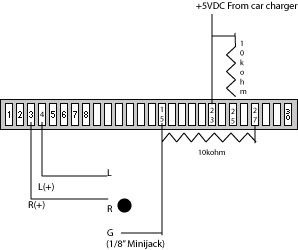 pinouts.ru posted:1 GND Ground (-), internaly connected with Pin 2 on iPod motherboard SuicidalSmurf fucked around with this message at 09:25 on Feb 6, 2008 |
|
#
?
Feb 6, 2008 08:25
|
|


|
SuicidalSmurf posted:Also, the way I am reading the pinout (#27), will I need to do this resistor tomfoolery to charge the ipod (this is the newest ipod classic 80gig), or is there a better way. After having read USB spec for the last three days, I suspect yes. You're putting voltage on the USB bus lines to make it look like there's a USB bus actually connected. Without those resistors, the ipod won't believe the rest of your "tomfoolery", no matter how correct your voltages are.
|
|
#
?
Feb 6, 2008 11:00
|
|

|
kid sinister posted:Here's a question. I just noticed that the caps on my motherboard were bulging. It's old and out of warranty, but I'd like to keep this machine running. I'm pretty handy with a soldering iron and I'd like to replace these caps myself. My problem is that I'm kinda overwhelmed with the selection at Digikey. According to the stats on those bad caps, I'd need some 2200uF 6.3V caps and some 1500uF 16V caps. Do I just need to match up those numbers for replacements? look for additional information on the old caps. There should be a temperature rating and possibly a series indicator marked on their cases. You want to at least match the temp rating. If you can determine what series they are, search for it on digikey (or google if it's really old) and you can get all its specs there. For large supply caps, you'll generally want low ESR, good temperature stability, and high ripple current ratings. How good these parameters need to be depend on the circuit, but I don't think we'll know that much. I wouldn't sweat it too much.
|
|
#
?
Feb 6, 2008 11:15
|
|


|
I was ECE for a year and a half before switching to a major that I'm actually good at and this thread gives me nightmares. Honestly I want to applaud everyone who gets this stuff, especially if they're not formally trained in it. Give me 300 pages of economic theory any day 
|
|
#
?
Feb 6, 2008 17:00
|
|


|
Hey anyone willing to give me a hand with a circuit. It's called a negative impedence converter, it's built around op amps and you use it to make filters. The idea is that the effective input impedence will be -Z, where Z is whatever you connect between the inverting input and ground. It looks very much like a typical op-amp current source, but the positive feedback is wierd. feel free to use a lot of profanity if you want. 
Zaxxon fucked around with this message at 18:40 on Feb 6, 2008 |
|
#
?
Feb 6, 2008 18:38
|
|

|
Azathoth posted:I found this a while back and it's been gnawing at me something fierce. I've always wanted to learn electronics but I've never had something I wanted to build before. Since no one is answering you: If you purchase a printed circuit board and all the parts, this shouldn't be difficult to put together. Just ensure that your soldering iron is 15-20W, because as a novice it's very easy to burn the traces right off with anything more than that. If you don't use a printed circuit board, I would purchase a prototyping breadboard and lay the circuit out on that first to make sure you are reading the schematic clearly. Then you can work on transferring it over to perfboard or something like that. Honestly, though, with your level of experience just order the circuit board pre-printed and you'll be ok. Just learn how to solder on a piece of crap radioshack copper clad perf board and make sure you're doing it right before moving on to the stuff that costs money. Pro Tip: as you fill in parts, whether you use a schematic or a layout diagram, use a highlighter to fill in the parts you have done as you go. That way you can relate where you left off, what you have left to do, and you don't do more than one part at a time, therefore ensuring you make as few mistakes as possible (though you WILL make some).
|
|
#
?
Feb 6, 2008 20:25
|
|

|
Another electronics 101 question. I need to pick up a theory book. I remember what it is that I want, but how to get it done is a mystery to me. I'm not even sure which type of transistors I want to use, I just want to throw a circuit together and have a work. Understanding how it works would be an added bonus. I want to set up a logic gate. I have a momentary push button, B1, that I want to toggle a power source (+12vdc). So, on button press.. if theCircuit = 0 then turn it on if theCircuit = 1 then turn it off If anyone has an easy to understand guide on this stuff that would be great, but I'm a little over my head.
|
|
#
?
Feb 6, 2008 23:34
|
|
|
SuicidalSmurf posted:Another electronics 101 question. I need to pick up a theory book. I remember what it is that I want, but how to get it done is a mystery to me. I'm not even sure which type of transistors I want to use, I just want to throw a circuit together and have a work. Understanding how it works would be an added bonus. Look at the 'Lessons in electric circuits' link on the first page, or here. He covers digital stuff pretty well, and gives you some transistor level-schematics to work with. It looks like what you want is an AND gate or a NOR gate with an inverting input. You can make that with...6 BJTs I think (yep, just simulated it). You could also just get a 74LS00 chip (4 NAND gates on a chip, very common chip) and do it with 3 of those gates (which involves wiring parts of that chip together. I'd do the latter, unless you're trying to learn how gates work. It's cheap, easy, and you get to brag about having a (late 80s) computer chip on your board to anyone who cares.
|
|
#
?
Feb 7, 2008 00:22
|
|

|
SuicidalSmurf posted:Another electronics 101 question. I need to pick up a theory book. I remember what it is that I want, but how to get it done is a mystery to me. I'm not even sure which type of transistors I want to use, I just want to throw a circuit together and have a work. Understanding how it works would be an added bonus. This is a flip-flop, specifically a "T" flip-flop. You can get them on chips individually or wire them with a small number of gates. A TFF is just a kind of JK flip flop with the inputs connected together. http://www.play-hookey.com/digital/jk_nand_flip-flop.html
|
|
#
?
Feb 7, 2008 03:23
|
|
|
I asked this somewhere else, but I'll ask again here: If you connect an LED whose voltage drop is 1.2V at max current to a 1.2V source, why do you still need a resistor in the circuit?
|
|
#
?
Feb 7, 2008 03:26
|
|
|
Zaxxon posted:Hey anyone willing to give me a hand with a circuit. It's called a negative impedence converter, it's built around op amps and you use it to make filters. Think about it this way. Define impedance as V/I. Assuming the op amp is not saturated, the voltage at the noninverting input (Vin) will equal the voltage at the inverting input. So the current across Rz will be Vin/Rz, as will the current across the negative feedback resistor (call it R2). In this sense it pretty much is a current current source. The output of the op amp will be Vin(1 + R2/Rz). Therefore the current across the positive feedback resistor (call it R1) will be [Vin(1 + R2/Rz) - Vin]/R1, or -(Vin/Rz)(R2/R1). This current is negative because it's flowing into the voltage source. Normally this circuit will be built with R2 = R1, so it simplifies to I = -Vin/Rz. Do some algebra and you get -Rz = Vin/I. Therefore, since we defined impedance as V/I, Zin = -Rz. Bam.
|
|
#
?
Feb 7, 2008 03:29
|
|
|
babyeatingpsychopath posted:I asked this somewhere else, but I'll ask again here: Are you asking because your supply voltage is low, or because you just don't want to bother with resistors?
|
|
#
?
Feb 7, 2008 03:34
|
|
|
babyeatingpsychopath posted:This is a flip-flop, specifically a "T" flip-flop. You can get them on chips individually or wire them with a small number of gates. A TFF is just a kind of JK flip flop with the inputs connected together. Oh, ha, I should have asked. Did you want the output of this to be a momentary on (like a push button switch, motherboard power switch) or an always on (like a normal light switch)? If the latter, then yeah use a flip flop. It takes alot of transistors to build those unfortunately, I'd say (for TTL) 2 NPNs per NAND gate, 2 NPNs per input for step-up, 1 for an inverter (using the second input transistor), and 1 NPN for an output driver. There are 8 NAND gates in a flip-flop. So you need Otherwise, if you're just 'gating' the push-button switch (option #1), it takes about half that many transistors. Less if you don't care about glitches and such. clredwolf fucked around with this message at 04:49 on Feb 7, 2008 |
|
#
?
Feb 7, 2008 04:11
|
|
|
I need the latter, push button for a moment, power goes on. Push button again, power off. If it's gonna take 20 transistors then the hell with it, I'll use a regular switch. I won't learn as much, but I won't want to kill myself either.
|
|
#
?
Feb 7, 2008 05:46
|
|
|
Alright I just blew up an LED by hooking it up to a 9V battery without a resistor. So I've got a quick question, can I hook up a resistor on the cathode side of the LED like this: Or does it have to be on the anode side? I'd try it out but I don't have any more LEDs I can sacrifice.
|
|
#
?
Feb 7, 2008 06:09
|
|

|
Yergacheffe, this might clear some things up. http://en.wikipedia.org/wiki/LED_circuit 1) Use your spec sheet to find the current capacity of the LED. 2) V=I*R 3) 9-1.2=I*R 4) Sub in the current capacity for I, solve for R and pick up a resistor to put in place! Edit: Almost forgot, round up on the resistor value, rounding down can cause issues. Dewski fucked around with this message at 06:39 on Feb 7, 2008 |
|
#
?
Feb 7, 2008 06:36
|
|
|
yergacheffe posted:
|
|
#
?
Feb 7, 2008 06:57
|
|
|
Could someone explain impedance to me? I have a kind of fuzzy understanding of it -- I can kind of see how if you're trying to run a high frequency signal through a long wire, stray capacitance and inductance and the natural resistivity of the wire can degrade signal quality (I guess I kind of think of impedance as a special type of resistance that affects AC circuits). I know that for some reason, it's a good idea to buffer analog output from a microcontroller with an opamp before driving a speaker, but I've never really understood what a high impedance or low impedance load are, or what I'd have to do if, say, I wanted to alter an audio circuit designed for headphones to drive a larger speaker.
|
|
#
?
Feb 7, 2008 08:05
|
|
|
Thanks for the answers, for the curious I was building this PC fan controller: http://www.cpemma.co.uk/sdiodes.html As I understand it, this thing uses diodes to make voltage drops from the +12v rail of the psu, which in turn controls the voltage that the fan actually receives. My question is, why can't we use resistors or even a potentiometer to achieve the same effect?
|
|
#
?
Feb 7, 2008 09:41
|
|
|
mtwieg posted:Ideally it will be fine, but in practice it's a bad idea because the Vf will vary, even between similarly specified leds. If its Vf is 0.1V lower than expected, you may very well be looking at a double in current. And of course the voltage source will likely have its own issues with line and load regulation. I'm asking because it doesn't make sense (to me) to have a resistor when using a single AA battery to light an LED with a max drop of 1.4V. If the battery starts at 1.4V max and only gets lower as it discharges, why put more components in the circuit?
|
|
#
?
Feb 7, 2008 11:08
|
|
|
nobody- posted:Could someone explain impedance to me? If you stick to one or two reactive components, then it's pretty easy. A reactive component is one whose impedance changes in the frequency domain, i.e. inductors and capacitors. Search for wikipedia for passive low pass and high pass filters. It'll explain as well as I can.
|
|
#
?
Feb 7, 2008 14:56
|
|
|
Just think of it as a complex resistance. Mathematically, that's all it is. Resistance that varies with frequency.
|
|
#
?
Feb 7, 2008 16:31
|
|
|
babyeatingpsychopath posted:I'm asking because it doesn't make sense (to me) to have a resistor when using a single AA battery to light an LED with a max drop of 1.4V. If the battery starts at 1.4V max and only gets lower as it discharges, why put more components in the circuit? Because what if, due to manufacturing tolerance, your LED only has a 1.3v drop? Or your battery turns out to be 1.5v? You generally include a resistor as a safety margin and as a way to limit the current into the LED.
|
|
#
?
Feb 7, 2008 18:12
|
|
|
mtwieg posted:Think about it this way. Define impedance as V/I. Assuming the op amp is not saturated, the voltage at the noninverting input (Vin) will equal the voltage at the inverting input. So the current across Rz will be Vin/Rz, as will the current across the negative feedback resistor (call it R2). In this sense it pretty much is a current current source. The output of the op amp will be Vin(1 + R2/Rz). Therefore the current across the positive feedback resistor (call it R1) will be [Vin(1 + R2/Rz) - Vin]/R1, or -(Vin/Rz)(R2/R1). This current is negative because it's flowing into the voltage source. Normally this circuit will be built with R2 = R1, so it simplifies to I = -Vin/Rz. Do some algebra and you get -Rz = Vin/I. Therefore, since we defined impedance as V/I, Zin = -Rz. Bam. Ah ha, that makes sense. In my head I was thinking of the op amp input as sourcing a current, but they can't do that. Whoops.
|
|
#
?
Feb 7, 2008 19:02
|
|
|
babyeatingpsychopath posted:I'm asking because it doesn't make sense (to me) to have a resistor when using a single AA battery to light an LED with a max drop of 1.4V. If the battery starts at 1.4V max and only gets lower as it discharges, why put more components in the circuit? Here is an example IV curve I ripped out of a random Vishay datasheet:  The big issue here is to recognize how steep the IV curve is - a change of less than .1 V can double your current (or half it). Variations in both the LED and the battery will make it impossible/near impossible to get a constant brightness out of the LED. Alkaline batteries (1.5Vish) are especially bad at this as the voltage drops a significant (in this application) amount over the life of the battery. The life of the LED is could be a concern too if your circuit overdrives it. If you wanted a simple supply->led circuit, a current supply would make much more sense as you could bias the LED at exactly the brightness you want, but I suspect building a current supply vs. adding a resistor doesn't save you components. Delta-Wye fucked around with this message at 21:48 on Feb 7, 2008 |
|
#
?
Feb 7, 2008 19:38
|
|
|
SuicidalSmurf posted:I need the latter, push button for a moment, power goes on. Push button again, power off. If it's gonna take 20 transistors then the hell with it, I'll use a regular switch. I won't learn as much, but I won't want to kill myself either. Seriously, 74LS109 T-flip flop. 50 cents and it does exactly what you need without the muss and fuss of dozens of transistors. Just so you're aware, you can do this with far less, but you start running into nice little glitches then. The 109 is about the best way to do it. nobody- posted:Could someone explain impedance to me? I have a kind of fuzzy understanding of it -- I can kind of see how if you're trying to run a high frequency signal through a long wire, stray capacitance and inductance and the natural resistivity of the wire can degrade signal quality (I guess I kind of think of impedance as a special type of resistance that affects AC circuits). I know that for some reason, it's a good idea to buffer analog output from a microcontroller with an opamp before driving a speaker, but I've never really understood what a high impedance or low impedance load are, or what I'd have to do if, say, I wanted to alter an audio circuit designed for headphones to drive a larger speaker. Impedance is also known as 'complex resistance' in some circles. It's like resistance, but with 'imaginary' elements added (imaginary as in imaginary numbers, not made up stuff). <long there be dragons beyond this point> Turns out that capacitors and inductors can be effectively modeled as resistors with an 'imaginary' resistance instead of a 'real' resistance. Put the two together and you get a 'tank circuit'. Imagine a capacitor and inductor in parallel. If you put a DC signal through that, it goes purely through the inductor. A low frequency signal goes mostly through the inductor. A very high frequency signal can't go through the inductor, so it goes straight through the capacitor instead (which it 'sees' as low impedance). The combined effect means that at some middle frequency the current can go through both components, with more current than it would otherwise. This is the resonant frequency of the circuit. It's just like how an opera singer can shatter a glass, too low a pitch or too high a pitch and the glass stays intact. Hit that right note though, and it shatters into a million pieces. You could say that this circuit has high impedance at low and high frequencies, but low impedance at intermediate frequencies. It also turns out, that weirdly you can model non-perfect elements with a combination of perfect capacitors, inductors, and resistors. So a very long wire is modeled as a string of inductors and capacitors. </long> For most things, impedance usually equals resistance at a frequency, especially for audio stuff. An 8-ohm speaker hooked to an ohmmeter gives about 6 ohms, but when hooked up to an audio signal the amplifier 'sees' 8 ohms. Electrically, it's harder and harder to push a signal through the speaker at higher frequencies. At 1 MHz, for instance, you're not going to hear a thing out of that speaker, and the amp is going to see a very high impedance more than likely. It just can't push any current through the speaker that quickly. From about 20 to 20,000 hertz, most speakers are rated to have about the same impedance over that range. Some speakers go lower than that (subwoofers), some go higher (tweeters), and some stay in a middle range (midranges, of course). As for headphones and speakers, the difference is mostly current. An 8-ohm speaker takes a bunch more current than a 32-ohm headphone (4 times in fact). You'll need another amplifier between your device (microcontroller, iPod, whatever) and your speaker. For tiny little speaker, a good beefy opamp should do it. Larger speakers need larger amps, and bookshelf speakers or floorstanding speakers need big amps >20Watts to power...rare to find on a single chip (but there are some around). That help any? Kind of the long way to explain it... clredwolf fucked around with this message at 00:18 on Feb 8, 2008 |
|
#
?
Feb 7, 2008 23:50
|
|
|
clredwolf posted:Seriously, 74LS109 T-flip flop. 50 cents and it does exactly what you need without the muss and fuss of dozens of transistors. Looking at the specs for this chip on digikey, it appears the supply voltage is between 4.75-5.25v. This will be switching 12vdc. Is there a similar chip with higher voltage capabilities or am I missing something?
|
|
#
?
Feb 7, 2008 23:55
|
|
|
SuicidalSmurf posted:Looking at the specs for this chip on digikey, it appears the supply voltage is between 4.75-5.25v. This will be switching 12vdc. Is there a similar chip with higher voltage capabilities or am I missing something? You don't want to be using logic chips to directly drive anything. They can only source so many mA of current, and sink only a little bit more (refer to your data sheets for the exact numbers). Connect to the rest of your device through a transistor or relay.
|
|
#
?
Feb 8, 2008 00:13
|
|
|
SuicidalSmurf posted:Looking at the specs for this chip on digikey, it appears the supply voltage is between 4.75-5.25v. This will be switching 12vdc. Is there a similar chip with higher voltage capabilities or am I missing something? Forgive me if this seems like an obviously dumb suggestion, but why not just use a SPDT push button with an "alternate" or "on-on" or "locking" action instead of momentary? Just connect one side to ground and the other to your 12 volts (make sure it is a break before make switch). This seems like it would be the easiest way to switch 12v, especially if it is carrying some current.
|
|
#
?
Feb 8, 2008 01:13
|
|
|
SnoPuppy posted:Forgive me if this seems like an obviously dumb suggestion, but why not just use a SPDT push button with an "alternate" or "on-on" or "locking" action instead of momentary? Just connect one side to ground and the other to your 12 volts (make sure it is a break before make switch). That was the solution I ultimately arrived at, but I was initially looking at some fancy-pants implimentation.
|
|
#
?
Feb 8, 2008 01:54
|
|
|
Here's the trick. Open collector transistors can 'sink' (or provide a ground for) a higher voltage than your TTL supply voltage, up to near the voltage limits of the transistor. They are also conveniently active-high (they provide a ground at the collector when there is + voltage, and thus bias current, at the base, relative to the emitter.) Thats how you could switch a 12v source with your TTL level signal. Edit: Yay, my Futurlec order came in. 11 calendar days from order to delivery, and I got a bitchin' PACKAGE OPENED AND INSPECTED BY US CUSTOMS sticker off of it. The $2.95 multimeter is just fine for beginner work, and the breadboards are heavy and solid - I am very impressed with them. Jonny 290 fucked around with this message at 02:00 on Feb 8, 2008 |
|
#
?
Feb 8, 2008 01:58
|
|
|
Jairbrekr posted:Alright, heres one. Its pretty lame because I'm just not that angry and venomous anymore.... ACHTUALLY allaboutcircuits.com posted:When Benjamin Franklin made his conjecture regarding the direction of charge flow (from the smooth wax to the rough wool), he set a precedent for electrical notation that exists to this day, despite the fact that we know electrons are the constituent units of charge, and that they are displaced from the wool to the wax -- not from the wax to the wool -- when those two substances are rubbed together. This is why electrons are said to have a negative charge: because Franklin assumed electric charge moved in the opposite direction that it actually does, and so objects he called "negative" (representing a deficiency of charge) actually have a surplus of electrons. I can't believe I haven't seen this thread before!
|
|
#
?
Feb 8, 2008 02:39
|
|


|
Jdohyeah posted:ACHTUALLY I don't understand what you're trying to say here. Jarbrekr made an image of exactly what you just posted... he just left Franklin out of the discussion.
|
|
#
?
Feb 8, 2008 03:16
|
|
|
scholzie posted:I don't understand what you're trying to say here. Jarbrekr made an image of exactly what you just posted... he just left Franklin out of the discussion. Well he implied current was intentionally labeled to match hole flow, when it was just because of a wrong guess. Taught different things I suppose, I've actually never seen current flow represented as holes in anything but semiconductors. Jdohyeah fucked around with this message at 03:48 on Feb 8, 2008 |
|
#
?
Feb 8, 2008 03:46
|
|
|
mtwieg posted:Everything seems fine, then (though parts of the pdf won't display). The circuit I showed should be fine. The best way to regulate current would be with the series resistor. I doubt the diode's heat will have enough positive feedback to cause it to fail. I forgot to check this thread for a while. I have been using a higher voltage battery from the start (9V). I was merely interested in shrinking the size of the device. 9V batteries are too large for an aesthetically pleasing laser pointer, and they're far more expensive... $2.50 a piece. The blu-ray laser takes a bit more voltage to lase. It needs 5-5.5v just to run. I'm not sure exactly what I'm going to do for a cheap practical driver that uses 1.5V AAA just yet, but I definitely appreciate the input.
|
|
#
?
Feb 8, 2008 04:06
|
|


|

|
| # ? Apr 23, 2024 22:23 |
|
|
Jayls5 posted:I forgot to check this thread for a while. look into a23 batteries. 12 volts and half the size of a AAA. Not sure how much current they can deliver though. You can find them at most stores (radioshack for sure).
|
|
#
?
Feb 8, 2008 04:51
|
|