


|
3rd year ECE just wanting to say this thread is looking great. I am actually in the market for a nice oscilloscope now so I can work on some designs. I am really interested in a USB based solution since they seem to give a ton of the features of high end scopes while still being relatively cheap. And if you are going to be soldering lots of surface mount parts you might want to look into getting an air solder station instead of a iron based one. They use a solder paste instead of solder wire and a really fine nozeled hot air gun and by god do they make soldering .22" pitch parts easy. They really complement a nice soldering iron more than replace it since you are going to need the iron for larger parts, you can't really use paste to solder wires together, or for through hole parts. And for those of you who want to get into building your own PCB's we used http://www.4pcb.com/ in one of my classes and they offered pretty good rates. You provide them with a Layout file and they will make a pretty nice PCB. The instructors said we've ordered over 2000 boards from them and only 1 has had an error, and that was because two traces were too close together.
|
 #
¿
Jan 9, 2008 02:30
#
¿
Jan 9, 2008 02:30
|
|


|

|
| # ¿ May 1, 2024 00:22 |
|
|
joebuddah posted:Could somebody tell me a good book to learn plc programing? I'm probably going to buy a DL06 from automationdirect.com. I recently got some nifty automation devices for helping a friend tear down one of the machines at his job as they were selling it for scrap metal. We used the free manual from directsoft when learning to program ours. DS5 works on the allen bradley series which are pretty much an industry standard. Well the manuals are free on the website and the documentation for ladder logic was pretty straight forward. What are you trying to accomplish with the PLC though?
|
|
#
¿
Jan 9, 2008 18:29
|
|
|
spencer for hire posted:This is the main reason why I'm interested. I've found numerous sites online that have board layouts for different effects but I have yet to find a source for the reason behind placement of resistors and capacitors. Obviously designing my own pedal would be a project for the extreme future but I'd like to at least know the theory behind the design and how each part affects the sound. Do you have tips or know of any resources to how they shape sound? Like how would you go about designing a delay from scratch? If you provide me with a schematic I might be able to analyze it over the weekend and do my best to describe it in stages with SPICE simulations and 
|
|
#
¿
Jan 10, 2008 06:50
|
|
|
WilfBerT posted:Has anyone has an experience with these relatively cheap (~$200US) USB digital storage oscilloscopes? It can't do an FFT which probably can't be expected from any $200 scope but I really wouldn't buy a scope that couldn't do it. It's really nice to be able to see harmonic content of your output waveform especially in audio circuits.
|
|
#
¿
Jan 11, 2008 00:25
|
|
|
ValhallaSmith posted:I hate these things. They tend to be laggy and poorly featured. They work ok if you are just trying to automatically log some waveforms. But for interactive work they are kind of a pain. That is not entirely sure. We have some usb scopes in my labs that have no lag and have a slew of features present in more expensive in only the more expensive Tektronix. Things like FFT are a bit slower than an entire DSP based system like those in a good high end scope but still it functions well enough for basic measurements. Also the ability to dump data directly to excel is oh so nice, although you can do that with some of the newer cheap scopes anyway so it is a moot point. If you have an engineering school near you I recommend you check out their salvage store, whatever the hell they call it, mine had http://www.tek.com/products/oscilloscopes/tds1000_tds2000/index.html these for sale for like $50 a piece or something, of course they probably had the insides gutted about 30 times because of the silly freshman EEs killing them somehow(still not sure how to kill a scope but I've seen it done). Deals can also be had on craigslist pretty regularly if you live in a big city. I just started a class on DSP's and I can honestly say these are by far the most interesting things I have touched upon in any class ever. We are only a week into lecture and have already learned how to implelement relatively complex high order filters really easily. Digital ROCKS!
|
|
#
¿
Jan 11, 2008 14:57
|
|
|
Cyril Sneer posted:*sigh* we can work together to create the greatest things ever. The lines between digital and everything else are shrinking so fast that without a strong digital background I can't see how you really won't sink in the industry.
|
|
#
¿
Jan 13, 2008 06:42
|
|
|
Three-Phase posted:From what I've seen, digital and RF go hand in hand. Especially when you're talking about things like CE testing for noise immunity. It is amazing how diverse the field of EE is. It gets even more diverse when you throw the C in there and do ECE. It really surprises me it hasn't broken down further at this point at most major colleges since there really is no way for anyone to be proficient in all of this stuff by the time they graduate.
|
|
#
¿
Jan 13, 2008 23:28
|
|
|
UserNotFound posted:Right after "make your own power supply" should come "make your own DMM"! I used an ICL7106 integrated A/D and 3.5 segment LCD driver. The entire circuit can be constructed using basic circuit knowledge and information in the data sheet. Not a beginner project, but certainly something to do early on in DIY that it well explained in app. notes. Yeah you kinda need a dmm to calibrate your dmm though...
|
|
#
¿
Jan 16, 2008 01:33
|
|
|
I have noticed recently that my parts kit is really lacking in variety of components. I have sorted resistors and any parts I need for my classes but I would like to expand a lot. I really like the idea of buying the presorted resistor boxes and stuff because it is so much easier than going through them later. Anyway can anyone recommend a site that sells presorted components in pretty large numbers. Small Bear Electronics had a nice selection of caps but I am looking more into some 1% resistors, electrolytic caps, and well I don't even know anymore. Also a site that sells good soldering irons besides e-bay would be nice. I have a relatively decent weller adjustable iron but I am looking to move to a real soldering station with more precise temperature control. EDIT: I am an idiot and should have checked jameco. I have used them before but never realized they had the grab bag things which are awesome. Locker Room Zubaz fucked around with this message at 22:55 on Feb 2, 2008 |
|
#
¿
Feb 2, 2008 22:50
|
|
|
The talk of flip flops a few pages back brought back horrible memories of my intro to digital electronics class where we made a timing circuit using nothing but flipflops. I can't even remember how one works now!
|
|
#
¿
Feb 10, 2008 03:56
|
|
|
I got my Jameco grab bags the other day and drat were the parts crappy. I recommend the Electrolytic grab bag without question but the TTL one was basically 40 line buffers and a few CMOS NAND gates. Nothing really worth it at all. The Analog IC bag was just a ton of poo poo that is basically useless. I guess you get what you pay for.
|
|
#
¿
Feb 26, 2008 03:06
|
|
|
clredwolf posted:That's amazingly awesome. Jameco just kind of lumps everything together and sends it out the door. Sorting parts suck, especially when you can barely read the drat letters on some of those ICs. I definitely recommend the elecrolytics because they are a good range of values and voltage ratings and are actually useful. Oh i got the potentiometer grab bag and it was good too. Huge range of values and its a pain in the rear end to find proper potentiometer values. For resistors you can get a presorted box of 1-1MOhm values from most electronic stores.
|
|
#
¿
Mar 1, 2008 07:36
|
|
|
Has anyone made a working Class D amplifier? Or have any experience with them? I know it is basically just an H Bridge switching at incredibly high frequencies. I am wondering because I have to come up with my senior design project ideas soon and was thinking of doing a Home Theater receiver. I could use Class AB in there but what is the fun in that? Class D is the future and it is loving awesome because of how much less power is required and how efficient they are, I really don't want to spend 20hours designing a massive toroid based PSU for a class AB circuit anyway. So does anyone have any experience in them? Hell is anyone actually working with audio a lot? I really want to learn more about it, i only have basic DSP knowledge, so effects and poo poo like that, and a moderate knowledge of low power amplifiers, I built a 50W class AB amp in lab once but that was a while ago. If we have any acoustics guys I would be so happy if you could just give a rundown of some cool stuff, like what goes into a good amplifier design and things that are more complex than just MAKE THE SIGNAL BIGGER. I say this because I see tons of schematics for amplifiers on the internet and they do things different than what I have learned, and there is a pretty common theme between the designs.
|
|
#
¿
Mar 2, 2008 20:45
|
|
|
I wanted to get a DSP to mess around with, i think they are freakin cool, outside of class but drat are they expensive. For a decent AD Blackfin on a test board it is $500 
|
|
#
¿
Mar 6, 2008 18:02
|
|
|
Delivery McGee posted:I do have a toggle switch laying around unused. Not sure where I'd mount it, though, as it's pretty big. I wonder if I could repurpose the AM/FM switch, since I don't listen to AM radio. wouldn't you need a TPDT swtich for that? You have 3 channels that need switching, left, right, ground(Well ground might not need switching but left and right do). I would think a simple slide switch would work pretty well and would only cost a dollar or two at mouser.
|
|
#
¿
Mar 20, 2008 18:27
|
|
|
babyeatingpsychopath posted:The thing about opamps is they need dual voltages, because they amplify signals that have both positive and negative voltage. Without positive and negative voltage (or differential voltage, such as from a voltage divider) the opamp just won't work at all. It will "do stuff" but not what you think it should be doing. With DC filter caps on the input and output, it won't do anything at all. there are tons of single rail op-amps out there that put a dc offset into the signal so it can swing high and low, then you can just throw a decoupling cap on the output to remove the DC. quote:You realize the two are the same thing, right? Small, identical dots? Just that one comes with grammar and the other with numeric values? I don't know if they teach anything except equations and being a smug prick at engineering school. Get out of here you aren't providing anything to the discussion and are just being a lovely troll and enticing flames. This thread is about information and learning not about being a cock and bitching about people not wanting to do your work. edit: didn't realize there was another page on this thread. Locker Room Zubaz fucked around with this message at 17:51 on Mar 21, 2008 |
|
#
¿
Mar 21, 2008 17:46
|
|
|
Nerobro posted:While I don't have any lights on it, my bike helmet is red. :-) And I have a obnoxious red flashing taillight. My goal is to have enough light that I can ride confidently in the dark. the 2576 is a good part and will work fine for what you are doing. It gets a little finnicky at low input voltages, the spec sheet says it can go down to 2.5v input but it stops working at like 4, so if you are going to really low voltages stay away from it.
|
|
#
¿
Apr 1, 2008 22:46
|
|
|
Fifty-Nine posted:Resistor codes always end with a tolerance band which specifies the precision of the resistor's indicated value. It could be gold (+-5%), silver (+-10%), red (+-2%), or brown (+-1%). In practice I've only ever seen resistors with gold or silver tolerances, in which case you always read it starting on the side that opposite the gold/silver tolerance band. assuming it wasn't some freakish out spec component there are only so many standard values for components, standard values will be cheaper than a custom value so they will almost always be used. 1% code:code:code:And if the resistor has a 4th Band it is failure rate. Brown=1%, Red=.1%, Orange=.01%, Yellow=.001%.
|
|
#
¿
Apr 6, 2008 21:42
|
|
|
Mr. Powers posted:Does anyone have any familiarity with purchasing and interacting with image sensors? I'd like to start getting into some embedded computer vision projects, but I don't want to rely on dismantling GameBoy cameras for sensors that aren't very good anyway. I'd like to be able to get a camera element and feed it into an ADC and process from there, etc, etc. couldn't you hack apart a USB web cam and extract the bitstream?
|
|
#
¿
Apr 23, 2008 00:26
|
|
|
Mr. Powers posted:I don't know, that's why I was asking. I was hoping there was someone here who has more experience with this. my DSP teacher had a little camera he bought at a robotics shop that interfaced via serial port with our DSP and it had an integrated ADC on it. It was only like 1MP but i will ask him where he got it because that seems to be what you are looking for. I would think though that a skilled programmer could interface with a webcam but I don't know. I will google it I guess. Edit: Heh found what you were looking for http://www.jrobot.net/Projects/AVRcam.html
|
|
#
¿
Apr 23, 2008 19:29
|
|
|
Zuph posted:I'm having some trouble figuring out how to interface a handful of 14-segment displays to a microcontroller. The micro I'm using has enough power to drive the LEDs directly, but there's no way I can sink the necessary amount of current through the micro to properly multiplex the display. Allegro made a current sinking driver chip at one time, but it has since been discontinued, and Maxim makes a chip that does a fantastic job of controlling the displays directly, but it's $15 a pop, and moreover hard to find. you can use a BJT or MOSFET low switch to dump the current. A very cheap 2n3904, i think they are $.02 a piece, can deal with 100mA current sustained and 200mA peak and still operate pretty well at 25MHz, although you aren't going to be switching anywhere near that speed. The only problem with this is you are going to be using a ton of BJTs, one per segment.
|
|
#
¿
Apr 28, 2008 20:10
|
|
|
Zuph posted:I can drive the segments fine from the Micro (or, in this case, a shift register to minimize port lines), but each segment is common cathode, so I could (theoretically) need to sink up to 300mA of current. well there are higher current BJTs, they go up to about 1A, for cheap so current shouldn't be an issue. The real issue will be wiring everything.
|
|
#
¿
Apr 29, 2008 18:36
|
|
|
mtwieg posted:I've been busy lately with finals along with my own ongoing development of a major project, so I've been busy lately. Next update will probably come in the next couple days.
|
|
#
¿
May 8, 2008 00:19
|
|
|
Hypnolobster posted:I just ordered a Weller WES51, which is going to be loving great, because I've been stuck with pencil irons ever since I started dicking around with electronics. I ordered it to enhance the enjoyment of my newest project (tube-hybrid headphone amp). jameco has great prices on wire from my experience. They also have a ton to choose from and will do special orders if you nag em.
|
|
#
¿
May 13, 2008 06:41
|
|
|
SnoPuppy posted:If you ground the negative rail, everything in the opamp will be referenced to a "virtual ground" that is Vcc/2. Thus, you would need to AC couple the input and outputs, otherwise you will get a signal that has a strong DC offset. not all opamps will function without a negative supply. A lot will just do nothing unless you power them properly so be careful with this and read the datasheet.
|
|
#
¿
May 18, 2008 17:15
|
|
|
PickledFetus posted:What is a good way to get started with microcontrollers? I am taking an Embedded Systems class right now and we're using Xilinx MicroBlaze, which is a soft-core VHDL microprocessor that you synthesize onto an FPGA. Its pretty cool because you can synthesize all kinds of on-chip peripherals (UARTS, timers, memory, etc) depending on what you want for your design, but the board itself is kind of expensive, so I'm looking at a number of cheaper hardware uCs to use in smaller projects. I know the AVR is popular, but I'm looking at all the info at https://www.avrfreaks.net and its kind of intimidating - whats a good AVR chip and development/programming platform to start with? I'm not necessarily tied to the AVR, either, it just seems like its a popular platform. an atmega16 is a really nice full featured micro and I would recommend it from my experience.
|
|
#
¿
May 19, 2008 05:14
|
|
|
Mr. Powers posted:http://www.mypic32.com/web/guest/home gonna have to throw something together in visio so it looks really pretty.
|
|
#
¿
May 28, 2008 15:43
|
|
|
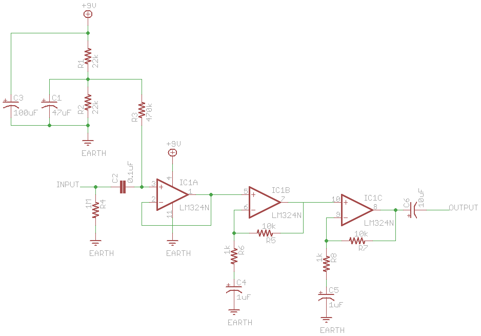
Chalupa Joe posted:why not do two gain stages in series each with a gain of somewhere around 10? Why do inductors not have noise? I would think being large coils of wire they would act as antennas inducing noise into the circuit. I have also heard of electrolytic capacitors inducing noise because they have all that bubbling goo inside of them. Please set me straight.
|
|
#
¿
Jun 13, 2008 15:01
|
|
|
Ok i'm starting on a project right now to make a scrolling LED display. I am really unsure of what i'm going to need and how to go about it, although I do want to do most of it by myself I figure why not at least get a starting point down. Here is my current plan, I am going to use a ATMEGA16 to control a big ole grid of LEDs. My plan was to make an addressing scheme similar to how RAM is access with a column address and a row address and divide the memory into that, maybe have the column be ground and the row's be hot. When the address is hit the LED will then turn on! Voila easy as pie. The issue with this is I need tons and tons of address lines, unless I multiplex the lines but then speed becomes an issue. How would be the best way of doing this? Am I completely over complicating this because if I am please tell me.
|
|
#
¿
Jun 17, 2008 23:32
|
|
|
RegonaldPointdexter posted:Usually, matrix multiplexing is the way to go when controlling an LED array. With an ATMEGA16, speed shouldn't be a problem at all. I am thinking of doing 10x200 in 5x7 matrices but that seems like a lot of soldering and burned fingers.
|
|
#
¿
Jun 20, 2008 20:45
|
|
|
Welp i found a great guide for making a LED array http://www.acm.uiuc.edu/sigarch/tutorials/ledarray/ looks to be the same thought process I went through too. Welp now to source some LED 8x8 grids and get this project started
|
|
#
¿
Jun 24, 2008 21:07
|
|
|
http://www.sparkfun.com/commerce/product_info.php?products_id=681 found some LED matrixs for anyone that cares. They are 8x8 and the company that sells these even makes a serial backpack so you can just send it a big array and it will decode it and stuff, although they are $50 a pop. It looks to me that I am going to need a ATTiny or ATMEGA on each matrix because there is no way I can address the entire 72x8 array with just a single chip because I need 18 outputs per chip, 2 for each column since they are bicolor LEDs and then 1 for the clocking of the counter.
|
|
#
¿
Jun 25, 2008 18:08
|
|
|
Does anyone know anything about ARM processors? I have worked on an Atmel before, i love those things, but these look simply too good to be true for a lot of the bigger projects I will be soon getting into since my senior project is coming up. So does that look like a good deal? or am i being stupid and should stick to Atmel?
|
|
#
¿
Aug 16, 2008 10:18
|
|
|
hobbesmaster posted:I take it you mean AVR? Because Atmel makes ARM7 and ARM9 based microcontrollers, amongst other things. They also have an interesting looking architecture in the AVR32 line. (also, check out the new AVR xmega series if you haven't already and have used the atmega series) Yeah I meant AVR, thanks for correcting me. And my senior project is also lots of image processing and i think it will require a good amount of computational power so I am looking into learning on the beagleboard. I am actually thinking about ordering one and just figuring it out as I go.
|
|
#
¿
Aug 16, 2008 22:26
|
|
|
Don't bother building anything remotely high frequency on a breadboard. There is so much parasitic inductance and capacitance so you will not get a working circuit no matter how hard you try.
|
|
#
¿
Aug 17, 2008 02:06
|
|
|
About to buy the beagle board and futz around with it. It looks to be a monstrously good deal for what's on board, i love that it has a DSP on it, and I want to learn to code for ARMs since they are so common in the market. Edit: Jeeze I was looking at the specs of this thing and it is ridiculous. I don't think I will even be able to scratch the surface of the capabilities of this with my limited embedded system knowledge. Still going to be a fun thing to mess around with i think. Locker Room Zubaz fucked around with this message at 05:12 on Aug 18, 2008 |
|
#
¿
Aug 18, 2008 05:07
|
|
|
Well the nice guys at Cypress Semi came to my school the other day and gave us a tour of their product and some free samples. They make the PSoC, Programmable System on a Chip, and it looks to be a pretty cool device for beginners and advanced users. Its a mixed signal array that lets you put both digital and analog components on the chip and it also has a relatively fast micro controller on it. For beginners it has a really simple drag and drop interface and for advanced users you can program the micro controller and pretty much design your own blocks for the analog/digital sections. The software is free to futz around with too so if you want to just see what developing for one would be like you can. If you are a student and shoot them an e-mail i would think you could work out a deal where you can get a discount or an eval board. Their page is really terrible for linking so if you want to check them out go to cypress.com and look into the "PSoC EVAL1 Academic Development Kit" in the store. I haven't really messed around with one yet but from the limited stuff i've done they seem to be a great way to do somewhat advanced stuff, like controlling an LCD or using an ADC, with very minimal coding.
|
|
#
¿
Oct 9, 2008 15:19
|
|
|
hobbesmaster posted:Don't worry, you'll hate it with a passion soon enough. Well i have used the PSoC a bit over the weekend and am still undecided on it. I think if I had no idea how to program a microcontroller I would think this is the greatest thing ever. The problem I have is I know what I want to do but it is incredibly hard to describe with some simple graphical blocks and transfer functions. For example I wanted to make a variable pulse PWM to control a servo. In the PSoC it took me about an hour to figure out the logic behind it. On my mega16 it took about 10minutes to figure out the timer preloads and set all the registers I needed. I think what it comes down to is how well you are planned to do your project. If you have everything planned out ahead of time, flow charts and all that jazz, you will be able to implement it on a real micro faster. However, if you have a vague idea of what you want to do a PSoC might be a bit better. I haven't really tooled around with the analog portion of the chip yet but it looks pretty cool
|
|
#
¿
Oct 13, 2008 07:20
|
|
|
Sweevo posted:I'm trying to build something to control a heated seat in a car. I did some reading and came up with this: I don't think a 741 will be able to source enough current to toggle that mosfet. I would look into using a buffer or open collector hex inverter, 7406, to get more current into the gate. As long as you exceed saturate the gate with Vcontrol>Vgs you will start the switch up but with very little current it is going to take a very long time to get the mosfet conducting. And just a little tip that might save you some problems later. Seperate the ground from the load control circuit and run it by itself directly back to the ground. This will prevent high currents being dumped through it, which will happen on inrush, from loving up the low level logic that is on the other ground. You can't begin to imagine the poo poo that gets hosed up when your ground suddenly floats to 500mV
|
|
#
¿
Oct 22, 2008 07:03
|
|

|

|
| # ¿ May 1, 2024 00:22 |
|
|
RivensBitch posted:I'm trying to interface an electret condenser microphone with a PIC 16F628A microprocessor. I just need a simple way to let ambient audio influence my program, so a simple circuit that flips a pin on the pic high or low based on a certain audio threshold would be great. Wouldn't it be possible to use a bandpass filter for the frequency range you want to get and then a comparator that detects when your predefined threshold is met. You could then just have the comparators output connected to the external interrupt pin which would then do exactly what you want. This is of course assuming PICs have external interrupt pins
|
|
#
¿
Nov 1, 2008 20:32
|
|