


|
Can anyone tell me where I can get lead free solder paste? Like a few hundred milliliters of the stuff. And REAL MEN drive their LEDs with current sources.
|
 #
¿
Jan 12, 2008 11:37
#
¿
Jan 12, 2008 11:37
|
|


|

|
| # ¿ May 2, 2024 14:15 |
|
|
slackingest posted:digikey.com or mouser.com should be able to hook you up. Also I dig the new mosfet av.
|
|
#
¿
Jan 12, 2008 22:40
|
|
|
ValhallaSmith posted:These guys have free 250g paste samples: http://www.smtsolderpaste.com/free_solder_paste.php And as for your power supply, you might be best off rolling your own linear regulator. It's fairly simple and there's no need for digital stuff (unless you want a built in meter or something). I can post an example schematic if you want. ANIME AKBAR fucked around with this message at 02:04 on Jan 13, 2008 |
|
#
¿
Jan 13, 2008 02:00
|
|
|
Jairbrekr would you be mad if I stole your gimmick and did a a minilesson on transistors? edit: poo poo, you did that already. Maybe I could do some example transistor circuits. ANIME AKBAR fucked around with this message at 02:57 on Jan 13, 2008 |
|
#
¿
Jan 13, 2008 02:46
|
|
|
ValhallaSmith posted:I've built tons of those. What I'm trying to come up with is something very cheap for the hobbyist. The reason I would go with a pic or avr is because using one of those over USB is cheaper than adding in everything you need for a display, controls and switches. Plus I want to keep these at a very small form factor (altoid form factor). I've been reading up on synthetic instrumentation for a chunk of the day. I might draw something up that heads in that direction. Instead of a power supply you could basically build a DAC. Then if you want a voltage meter you add a ADC voltage module. If you want power factor correction/metering you add a shunt resistor, amp and another adc. Basically a very generic instrument set that performs most of the measurement on the PC. It would be USB 2.0 based so that would kind of limit things at times. USB has crappy latency. The next logical step up from a linear regulator would be a switcher, which is what I think most good bench supplies use. But unless you're very concerned with load and line regulation, it probably wouldn't be worth the added complexity over a linear supply.
|
|
#
¿
Jan 14, 2008 18:17
|
|
|
900ftjesus posted:If you're at all serious about getting started in electronics, you need this book:  Horowitz and Hill Horowitz and Hill
|
|
#
¿
Jan 15, 2008 06:36
|
|
|
Mr. DNA posted:I need to control a solenoid from a microcontroller. The solenoid will need up to 1.8A. Is this a suitable MOSFET to use? STM STD50NH02L With a Vgs of 5V, your Rds will be around 10 milliohms. With 1.8 amps, it will be dissipating maybe 40 milliwatts. The mosfet is rated for 60 Watts. Given what capabilities you need, you shouldn't be paying more than a buck on whatever you choose. Look at some Fairchild semiconductor FETs. They make good inexpensive ones.
|
|
#
¿
Jan 18, 2008 02:51
|
|
|
for a project I need some good antistatic protection for the pins of my microcontroller. It has built in protection diodes, but I don't really trust them since their characteristics aren't specced in the datasheet. The easiest way would be to just put a resistance in front of the input, but the thing is I will be switching it to an output also, and I don't want it to have too high of an output impedance. So it seems my best option is to put on some redundant protection diodes. However, I'm not sure what kind to get. I'd assume Schottkys with good peak current ratings would be good, but I'm not sure. Any advice?
|
|
#
¿
Jan 23, 2008 02:48
|
|
|
ValhallaSmith posted:If you can get reasonably decent resolution on your PCB, you can try using spark gaps. They are pretty effective at ESD protection. Just have small spots where there is an unobstructed .5 mm gap to ground.
|
|
#
¿
Jan 23, 2008 03:52
|
|
|
Jonny 290 posted:From what I remember, linear power supplies are about 50-70% efficient depending on the design. Efficiency of linear regulators is Vout/Vin (if you assume quiescent current is zero, that is. It's usually so small it's negligible).
|
|
#
¿
Jan 26, 2008 00:55
|
|
|
Jayls5 posted:mtwieg recommended I post here. Generally the voltage is set the same way as an lm317: a resistor divider from output to ground, with the divided voltage being held at some reference voltage.
|
|
#
¿
Jan 28, 2008 03:20
|
|
|
Your circuit would look something like this: Your output could be adjusted via any of the three resistors. The exact design and component values will depend on your boost converter (datasheets typically tell you exactly what you need to know). When you say they give to much current out, I think you're misunderstanding what these things do. They regulate voltage, not current (though most will limit the current output). You control current by voltage and the load impedance at that voltage. ANIME AKBAR fucked around with this message at 04:18 on Jan 28, 2008 |
|
#
¿
Jan 28, 2008 04:15
|
|
|
charge pumps are nice for their simplicity and and efficiency, but they have their limitation. They're limited to low-current loads, since they require low-esr capacitors to work properly, and therefore you really can't just stick a giant electrolytic on the output to reduce ripple. Also, they are unregulated, so you're usually stuck with inverters or doublers. I use them when I want to make a tracking negative power rail for battery powered devices, but beyond that I'll usually go for a boost/buck converter.
|
|
#
¿
Jan 28, 2008 09:45
|
|
|
Jayls5 posted:Will something (such as a laser diode) only pull a specific current at a certain voltage? Is that why a steady voltage source implicitly acts as a current regulator? I was trying to tell my friend this originally if that's the case.  Usually you will operate it at around the "turn on" voltage, where it starts looking like a low impedance. Just putting a resistor in series with it of appropriate size will usually work fine (as in the schematic I posted). As for current regulation, it most likely isn't necessary. I highly doubt the properties of the diode will change enough to significantly change its power output. Do you have a datasheet for the diode?
|
|
#
¿
Jan 29, 2008 03:53
|
|
|
Jayls5 posted:I think this is the same one I have: Everything seems fine, then (though parts of the pdf won't display). The circuit I showed should be fine. The best way to regulate current would be with the series resistor. I doubt the diode's heat will have enough positive feedback to cause it to fail. If you really want to, you could use a circuit that makes a current source out of your voltage source. A simple one would be as follows:  A normal red LED provides a stable voltage reference of around 1.5 volts (this may vary from LED to LED, but the point is it remains pretty much constant regardless of the load on the circuit). The current through the laser diode will be (practically) equal to the current through R2. The voltage across R2 will be the Voltage of the red LED minus the base emitter voltage of the transistor (0.6 volts). To sum it up, the laser LED current is equal to (Vd - Vbe)/R2, or 0.8/R2. So you can easily adjust R2 to change current (just make sure it can't go to zero). You will still need to boost the voltage, since at the very minimum the LED needs 3 or four volts. Supplying this with five volts from a boost converter should be fine. The one downside of this is that it requires some extra current in order to get that 1.5V across the red LED. There are more efficient ways to do it, but they're fairly complex and aren't worth the trouble. Also, did you ever simple consider using a higher voltage batter?
|
|
#
¿
Jan 30, 2008 08:49
|
|
|
Wisdom posted:I notice Radio Shack sells these. Is this a good kit to use to get into the hobby? Try the microcontroller thread for this kind of stuff.
|
|
#
¿
Feb 2, 2008 01:25
|
|
|
kid sinister posted:Here's a question. I just noticed that the caps on my motherboard were bulging. It's old and out of warranty, but I'd like to keep this machine running. I'm pretty handy with a soldering iron and I'd like to replace these caps myself. My problem is that I'm kinda overwhelmed with the selection at Digikey. According to the stats on those bad caps, I'd need some 2200uF 6.3V caps and some 1500uF 16V caps. Do I just need to match up those numbers for replacements? look for additional information on the old caps. There should be a temperature rating and possibly a series indicator marked on their cases. You want to at least match the temp rating. If you can determine what series they are, search for it on digikey (or google if it's really old) and you can get all its specs there. For large supply caps, you'll generally want low ESR, good temperature stability, and high ripple current ratings. How good these parameters need to be depend on the circuit, but I don't think we'll know that much. I wouldn't sweat it too much.
|
|
#
¿
Feb 6, 2008 11:15
|
|
|
Zaxxon posted:Hey anyone willing to give me a hand with a circuit. It's called a negative impedence converter, it's built around op amps and you use it to make filters. Think about it this way. Define impedance as V/I. Assuming the op amp is not saturated, the voltage at the noninverting input (Vin) will equal the voltage at the inverting input. So the current across Rz will be Vin/Rz, as will the current across the negative feedback resistor (call it R2). In this sense it pretty much is a current current source. The output of the op amp will be Vin(1 + R2/Rz). Therefore the current across the positive feedback resistor (call it R1) will be [Vin(1 + R2/Rz) - Vin]/R1, or -(Vin/Rz)(R2/R1). This current is negative because it's flowing into the voltage source. Normally this circuit will be built with R2 = R1, so it simplifies to I = -Vin/Rz. Do some algebra and you get -Rz = Vin/I. Therefore, since we defined impedance as V/I, Zin = -Rz. Bam.
|
|
#
¿
Feb 7, 2008 03:29
|
|

|
babyeatingpsychopath posted:I asked this somewhere else, but I'll ask again here: Are you asking because your supply voltage is low, or because you just don't want to bother with resistors?
|
|
#
¿
Feb 7, 2008 03:34
|
|
|
yergacheffe posted:
|
|
#
¿
Feb 7, 2008 06:57
|
|
|
nobody- posted:Could someone explain impedance to me? If you stick to one or two reactive components, then it's pretty easy. A reactive component is one whose impedance changes in the frequency domain, i.e. inductors and capacitors. Search for wikipedia for passive low pass and high pass filters. It'll explain as well as I can.
|
|
#
¿
Feb 7, 2008 14:56
|
|
|
Jayls5 posted:I forgot to check this thread for a while. look into a23 batteries. 12 volts and half the size of a AAA. Not sure how much current they can deliver though. You can find them at most stores (radioshack for sure).
|
|
#
¿
Feb 8, 2008 04:51
|
|
|
Jonny 290 posted:OK, help me wrap my head around this one. I created a touch sensor out of a common collector amplifier with a 2n5306 darlington, a +5v bias voltage (for 4.3 at the emitter) and +12 fed to the collector (it's what was set up on my board at the moment). Load is a 2.2v drop LED with a 47 ohm resistor (ignore the bad sizing for now). How are you biasing it? Also, if you're using the darlington shouldn't you get around 3.6V at the emitter? Putting things together from a verbal description is hard. Maybe you could invest in drawing it, maybe in a simple CAD program (this goes for people in general)? And there are a few things in the human body model that could explain it. Capacitance is one. If you continue touching it, how long does current keep flowing? ANIME AKBAR fucked around with this message at 19:02 on Feb 9, 2008 |
|
#
¿
Feb 9, 2008 18:56
|
|
|
babyeatingpsychopath posted:Ok, if I remove the LED/transistor entirely and just read voltage at pin 3, still nothing. I've triple-checked everything. I've even duplicated this circuit on BOTH sides of my 556 to no avail. What gives? Also, just to try, take the bypass cap off the control voltage pin. I can see too large of a capacitance there possible screwing things up. 0.1uF is all you'll ever need. And what does the voltage across the timing capacitor read? ANIME AKBAR fucked around with this message at 08:13 on Feb 10, 2008 |
|
#
¿
Feb 10, 2008 08:10
|
|
|
babyeatingpsychopath posted:Ok, I'm back. I'm still dicking with that 555/556 blinky light maker. Umm you should never touch an output directly to a low impedance (either supply rail). That'll kill the IC quick. Touching thresh to Vcc should make the light should go off, so that's okay. Don't just go making random connections with the Vcc or Ground. Not without some resistance anyways. The schematic you posted will work, guaranteed. If it doesn't, then either you goofed up or a component is dead. hook it up in astable mode again. Here is a good test circuit for it (maybe use a bigger timing cap so it's slower): 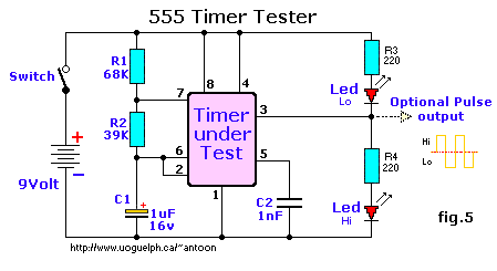 taken from this awesome 555 website, which you should read thoroughly. Make sure everything is right. Then probe the capacitor voltage. It should be changing between 1/3Vcc and 2/3Vcc. If it's above 2/3, make sure your discharge pin is attached. If it's below 1/3, make sure the trigger pin is attached. If it falls and rises between 1/3 and 2/3, then it's working. turbo sex bat 4000 posted:What's the best sketchy ebay store/angelfire website to buy luxeon type high power LEDs from?
|
|
#
¿
Feb 14, 2008 17:27
|
|
|
could you post the whole thing? I can't make heads or tails of the table.
|
|
#
¿
Feb 19, 2008 07:28
|
|
|
Cuw posted:I wanted to get a DSP to mess around with, i think they are freakin cool, outside of class but drat are they expensive. For a decent AD Blackfin on a test board it is $500 Sound card = DSP (audio frequency only, of course)
|
|
#
¿
Mar 7, 2008 20:10
|
|

|
Maynardr6 posted:This is the best video I've found so far for soldering surface mount stuff without really expensive soldering equipment like hot air guns.
|
|
#
¿
Mar 9, 2008 00:40
|
|
|
radioactivelego posted:I'm looking to do a little project that uses multi-color LED's that react to sound. Imagine an 80's LED tachometer except it reacts to sound (or hey if frequencies are possibly even cooler). It'd be hooked up to a computer microphone and would be aimed at a sound. dB or frequencies I want 5 different color LED's (like a blue to white gradient) that react and light up based on levels. I would imagine some form of resistors would be in order and would revolver around voltage dropping etc. Some sort of variable potentiometer? Reacting to frequency is a great deal harder, because unless the sound is a perfect sine wave, any sound will have many frequencies in it. If you're looking for one or more specific frequencies, you could build a bandpass filter for each frequency then rectify the output as before. But if you want to look at continuous range of frequencies you'd effectively have to build a spectrum analyzer, which is pretty deep stuff.
|
|
#
¿
Mar 26, 2008 22:37
|
|
|
babyeatingpsychopath posted:I got an LM317 voltage regulator, and it's totally tits. The datasheet for the thing is 26 pages long, six of which are schematics showing you how to do stuff. the lm317 is a solid device, though one of the things that bugs me about it is that it will only operate correctly if you load it with at least 10 or so milliamps, so it blows as a low power reference but is good as just a supply. Linear regulators are pretty simple and they can be built from a few transistors and stuff pretty easily. There tons of tutorials online. You just have to understand how negative feedback works. That's how most analog circuits work.
|
|
#
¿
Mar 29, 2008 03:37
|
|
|
I was thinking about making a series of posts each constituting a lesson or two on common circuits and techniques, eventually culminating in combining them into something cool. I had three different things in mind: DIY switching power supply, which would cover the following: Comparators and hysteresis Relaxation oscillators Voltage controlled PWM Switching supply theory Voltage references Error amplification Closed feedback loops DIY DC motor speed controller: Pretty much the same as above, except replace Switching supply theory with H-bridge theory DIY linear regulators: Zener diodes Transistor lesson Voltage references Error amplifiers Closed feedback Reply if you're interested in this. I'd rather not start on such an endeavor unless there is some demand.
|
|
#
¿
Apr 11, 2008 16:32
|
|
|
Okay, I'll go with switching power supplies, since I'm a bit more experienced with them than with motors. I'll go over some basics first. A lot of you have probably used op amps before, but if you don't actually know how they function, you should read this anyways. Differential amplifiers part I: op amps and negative feedback  A differential amplifier is a three terminal device, two inputs (named V+ and V- in this picture) and one output (Vout). The differential amplifier, like all amplifiers, is an active device, meaning its output power can be greater than the power from the inputs. Therefore, it needs a power supply, which is applied between to two supply pins (named Vs+ and Vs-). Its function is to give a voltage at its output that is proportional to the difference between its two inputs. So the the output will be: [(V+) - (V-)]Ao = Vout where Ao is the gain of the amplifier (or open loop gain, specifically). Typically, differential amplifiers have very, very high open loop gains, usually ranging from thousands to millions. Of course if you apply a couple volts between the inputs, don't expect thousands of volts at the output. The voltage of the output can't exceed the supply voltages. So what are these things good for? Why would anyone want such crazy gain? First lets note some other key characteristics of these things: -The inputs have very high impedance, meaning that they essentially do not draw current from the signal applied there. -The output is very low impedance, meaning it can supply lots of power and not change in voltage. What this means is that these things, while kind of useless on their own, can do awesome thing in closed loops. This means that the output is somehow fed back to the input, resulting in feedback. Feedback is the key to using these devices. Negative feedback is the most common form. Negative feedback means that a certain change in the input will result in a change in a change in output, which through whatever feedback path we have, will oppose that change. Lets take a look at a simple example:  Lets say that both inputs and the output are at 0 volts. Then we raise the positive (also called non inverting) input a tiny bit. What will happen? Our differential input voltage (a fancy way of saying the voltage of V+ minus the voltage of V-) has increased, which will cause a change in the output voltage (in will increase, since the differential voltage has become positive). But wait! Since the output is fed back to the negative input (aka the inverting input), that will cause its voltage to shoot up as well! This will in turn cause the differential input voltage to become negative, thus causing the output to get lower, causing the input to switch.... et cetera! That's negative feedback. A changing output is fed back to oppose itself. And while it may seem like it leads to a catch 22 situation, this actually meant the output will be very stable. How is it stable you ask, when its gain is so huge? When both inputs are essentially at the same voltage. That's it. When analyzing a circuit with one of these diff amps, you assume that its inputs are at the same voltage. Since the gain is so high, if there was even a tiny difference, the output would saturate (meaning its output voltage would swing to the minimum or maximum allowed by the supplies). Of course, ideally, an differential input voltage of exactly zero would give an output of exactly zero. Trust me, this is not something to worry about. Even in real life, the actual difference will likely be on the order of microvolts, far below what most people are concerned with. So what was the function of that circuit? Well, we say its inputs are at the same voltage, and one of the inputs is tied to the output, so its output voltage must equal the voltage at the non inverting input. This is called a unity gain buffer, meaning it has a closed loop gain of one. It's very useful for when you have a signal from a high impedance source that you want to use to drive a low impedance load. Since the input impedance of the amp is very high and the output impedance is very low, you can use it to essentially "buffer" a weak signal, enabling it to power heavy loads. Diff amps intended for negative feedback applications are called operational amplifiers (op amps). They're incredibly common and can do insane amounts of things. For these lessons, wheel really only use them for signal amplification. When analyzing circuits with op amps, things to keep in mind are: -The inputs are always at the same voltage (assuming the amplifier is not saturated) -There is no current flowing in or out of the inputs. -The output impedance is zero. To give a taste of what op amps can do, here is a little sampler The first four on the first page are basic voltage amplifiers. The closed loop gain equations are given, but you can derive them yourself by following the analysis rules given. As for the rest... good luck. Next time: Diff amps part II: Comparators and positive feedback ANIME AKBAR fucked around with this message at 02:20 on Apr 12, 2008 |
|
#
¿
Apr 12, 2008 00:45
|
|
|
Diff amps part II: comparators, hysteresis, and positive feedback. The very high gain of diff amps can also be used even without negative feedback. Consider the case where there is no feedback at all. If the two inputs are different by even a tiny bit, the output will be saturated at either the positive or negative supply rails. If V+ is greater than V-, then the output will be high, and vice versa. What we have is called a comparator: a device that compares two voltages and gives an output based on which which input is greater. This is useful for when you are looking for whether a certain signal is below or above a certain threshold voltage. Just connect a reference voltage to one input and the signal to the other, and the output will give a high/low output based on which is greater. For some applications, that's enough. No feedback or anything. However, much of the time one or both of the inputs will be noisy, meaning that they are not perfectly constant, but instead "jitter" a little bit randomly, usually by just a few millivolts. This means that if your two input voltages become close to each other, the output of the comparator may switch rapidly from high to low. Even if on average one input is always a little above the other, the noise might cause the it to fall below the other very briefly. The comparator will see this, and the output may change. Sometimes this is very undesirable, especially if the comparator is driving an edge-triggered device.  ^^Here we see a signal that is gradually rising over all, but has noise on it. The horizontal line is the threshold voltage. The noise causes it to cross it several times, leading to many transitions on the output. So what to do? In this case we use positive feedback. Consider the following circuit:  The signal is applied to the positive input. Our reference voltage is at the positive input, and is set by the 10K resistors between the supply rails (+5V and 0V), so it will be close to 2.5V. However it is also affected by the output via the 100K resistor. So if the output is high at 5V, then the threshold voltage will be pulled up to about 2.62V, and when the output is low, the threshold will be pulled down to about 2.38V. That is our feedback, and we can tell it's positive because it reinforces itself (high output causes V+ to increase, which causes causes the output to saturate high even more, etc). An easier way to tell is simply that the output is fed back to the positive input. So how does this help? Well lets say that our input is at 2 volts and our output is high, meaning the threshold is at 2.62V. Now we slowly raise Vin until it reaches 2.62V. The instant it does, the output transitions low, causing the threshold to be pulled down to 2.38V. Now in order to change the output again, we would have to bring Vin below 2.38V. So even if noise causes our Vin to wiggle around by a few millivolts, this will not cause extra transitions on the output. This is called hysteresis. It means that once you enter a certain state, the device will resist changing to another. How much it resists change depends on your resistor values. If we were to make out 100K resistor into 10Megaohms, then the feedback would have a "weaker" effect on the threshold (in this case, the threshold would only change from 2.488 volts to 2.512 volts). We can represent this visually:  Labeled here are our two possible threshold voltages (T and -T) and our two possible output voltages (M and -M). There are two different paths between the two thresholds. If we start with the input below -T and increase it, we will follow the lower path until we reach T, then the output will transition high. Once this happens, if we decrease the input below T, we will now take the upper path until we fall below -T and the output will fall low again. And repeat. Note that this graphic, where increasing the input causes the output to go high, is not the same as the previous example, where increasing the input causes the output to fall. This is because in the first example, Vin was connected to the negative input, while the graph corresponds to a circuit with the input connected to the positive input. It can be done either way. It all depends on the specifics of the circuit. The difference between the two threshold voltages is called the hysteresis gap. If, as in our first example, we wanted to prevent signal noise from changing the output, then the hysteresis gap would have to be at least as large as the amplitude of our noise (usually less than 10mv). However, there are much more interesting things that can be done with hysteresis, as we will see next time: Relaxation oscillators and PWM. Also, I said before that comparators and op amps are both differential amplifiers, and this is fundamentally true. However, they are not necessarily interchangeable. Devices specified as op amps are meant to be used as op amps and comparators are meant to be used as comparators. They have different properties that make them suited to one purpose (for example, comparators are usually faster and have higher gain, and have logic or open collector outputs, while op amps will have lower gain, frequency compensation, and push-pull outputs. Don't worry a lot about this terminology, for now).
|
|
#
¿
Apr 15, 2008 02:36
|
|
|
Not getting much response I see. I'm I going too fast/slow? Too technical? Too boring? Relaxation oscillators and PWM Before getting to some good stuff, we have to understand one more circuit. It's called an integrator, and it's built using an op amp:  Recall that we learned earlier that when analyzing op amp circuits, we assumed that the two inputs are at the same voltage. This means that for this circuit, both inputs are at 0 volts. Therefore the current through R must be Vin/R (we'll say current is positive to the right). Since the input does not draw current, all of the resistor current flows through the capacitor. A capacitor's voltage will change at a rate proportional to the current through it, or to put it clearly:  After we do all the math (I'll leave it to you to prove it to yourself), we find that the output is equal to:  Or, quite simply, the output will be the integral of the input, divided by -RC. If we were to put a positive DC voltage on the input, the output would ramp down linearly over time. It's slope would be -Vin/RC. Of course, it would stop once it saturates. Again, we have to keep in ming the limitations of the op amp. So, not that we've got that, we can combine the integrator with a comparator to make an oscillator. We do this by taking a comparator with hysteresis and an integrator and connecting them together:  Lets look at this step by step. First, lets say both devices are powered by +10 and -10 volts DC. Let us also assume that the output of the integrator starts at 0 and the comparator's output starts out low. Two things happen here: First, the + input of the comparator will be pulled negative by the output. Second, integrator will start integrating the output of the comparator, causing it's output to rise linearly (remember the output will be the negative integral, so a negative input does cause a positive sloped output). As the output increases, it will pull up the + input of the comparator, eventually causing it to become positive. The comparator output will immediately transition high. Now the integrator output will start to fall. Again, this will continue until it pulls the + input below zero again, causing the cycle to repeat itself. The output of the integrator will sort of "bounce" between the two threshold voltages created by the comparator hysteresis. Upon crossing either one, it will reverse direction and approach the other, forever. What we have made is called a relaxation oscillator, also sometimes called a multivibrator. This simply means that it works by charging and discharging a capacitor over and over. Notice that this generates two waveforms. The output of the comparator will be a square wave with amplitude equal to the supply rails. The output of the integrator will be a triangle wave, meaning it's edges are linear. The amplitude of the triangle wave will be equal to the hysteresis gap of the comparator. The frequency of both signals is determined by all the components. I'll save you the math and just give it here:  Understand that frequency depends on the hysteresis gap and the slope of the integrator. A smaller hysteresis gap will cause frequency to increase, since the linear ramp will have less "bounce room," and increasing the slope of the integrator will increase frequency, since it will travel across the hysteresis gap faster. Now this is cool, but what is it good for? Well, we can use this to make a pulse width modulator (or pwm) quite easily. First a few things about PWM. A pwm outputs a rectangular wave with a variable duty cycle. A rectangular wave looks like this:  It simply alternates between a high and low voltage at a fixed frequency. We call it a square wave when the high time is equal to the low time. When the high and low time aren't equal, like in the above picture, then we can describe the wave with the duty cycle. The duty cycle is the percent of the total period for which the signal is high. If the on time is t and the total period is T (like in the picture again), then the duty cycle is t/T * %100. So for a square wave, the duty cycle is 50%. For the pictured wave form, the duty cycle is around %33. Turning our triangle wave into a pwm is easy. All we do is feed the triangle wave to one input of a comparator and a variable voltage to the other.  If we connect it as above, the output will be high when the triangle wave is above the DC threshold. So if our DC is high, the triangle wave will be higher for a small amount of time. If the DC is low, then it will be higher for more of the time. Therefore we have built a voltage controlled PWM. The frequency of the PWM will be the frequency of the triangle wave and its duty cycle will be determined by the DC input voltage. For this configuration, higher voltage will give lower duty cycle. By switching the comparator inputs, we would get higher duty cycle for higher input voltages. Next time: Switching supply basics
|
|
#
¿
Apr 16, 2008 03:47
|
|
|
StumblyWumbly posted:Fun electronics fact: Most digital chips that do PWM output actually have analog innards which produce the PWM the same way mtwieg's oscillator works. High accuracy timing is done in a similar way, with the chip internally producing a voltage ramp and stopping that ramp when the clock is supposed to stop, and doing an analog to digital conversion to figure out the time.
|
|
#
¿
Apr 16, 2008 06:04
|
|
|
Keebler posted:No no this is good, keep 'em coming! try this: http://www.national.com/an/AN/AN-31.pdf BatDan posted:No I think this is interesting, but this forum moves pretty slowly so I think it might take a while for a lot of people to see it. I just graduated from OSU in Eng. Phys. and I didn't get to take as many EE courses as I would have liked, so this is useful to me too.  babyeatingpsychopath posted:Would it be suitable to make an LED flash based on battery level? If you wanted to have the brightness of an led vary with voltage, then that's easy. Voltage to current converters can be made out of just a transistor (or an op amp) and a few resistors. I think current sources were covered earlier in the thread. StumblyWumbly posted:If you want to learn practical analog engineering, pick up The Art of Electronics, more commonly known as "Horowitz and Hill." Seriously, I wouldn't be surprised if literally every EE who does analog work has this book. It goes from the fundamentals of analog electronics, like impedance and what a resister is, to transistors and op-amp level design. It has some great reference designs, and is all written for easy readability, like mtwieg's posts. Seconding this. Horowitz and Hill was the textbook for my applied circuit design class, and it's the only engineering textbook I actually use outside the course. It's beginner friendly, but also very practical and thorough. ANIME AKBAR fucked around with this message at 00:16 on Apr 17, 2008 |
|
#
¿
Apr 17, 2008 00:08
|
|
|
It can seem overwhelming if you skip important parts. If you try to learn about miller compensation without first looking at frequency response and transistor models, it won't make sense at all. HH is admirably good at verbalizing concepts, but you can't skip all the nitty gritty stuff either. It's likely that you were just missing some basic precursor concepts. Any thing in particular you were having trouble with? I may or not be able to explain it myself, but I should be at least able to point you to the right resources.
|
|
#
¿
Apr 17, 2008 15:53
|
|
|
jovial_cynic posted:Is there an easy way to wire the power-transistors in place that would work similarly to the LM1875? The gain clone is an easy circuit to build up, and basically, I'm just wondering if there's a way to swap in the power-transistors from the JVC into the circuit with minor modifications. Making transistor ac amplifiers is pretty simple, but op amps are generally really complex, and if you want high fidelity, then you want op amps. hobbesmaster posted:The problem is that your time is worth money, that black box is one less thing you have to design and implement. et cetera. ANIME AKBAR fucked around with this message at 02:24 on Apr 19, 2008 |
|
#
¿
Apr 19, 2008 02:15
|
|
|
SnoPuppy posted:I dunno - even some of your examples are kinda iffy. If I want a precise clock source, I am willing to pay for an oscillator that has < 0.5 ps of jitter rather than try to develop and debug one myself. Plus a stand alone oscillator takes up less space on a PCB than several discrete components. PLLs have their place when you are trying to get two clocks in phase with one another, or when you need to have very low clock skew (zero delay buffer). If you're making an MCU for the navy or the control for a pacemaker, then sure, go for it. jovial_cynic posted:Well, that was my first idea, but after doing some more research, it doesn't look like that's the way to go. I guess a better approach would be to get an understanding of how basic solid-state amplifiers work. I can follow instructions as easily as the next guy, but I'd like to know why things work the way they do, so I can take the power-transistors I've got and build an audio amplifier around them. Google turns up a lot of good stuff on how op amps work. That's mainly how I learned about it. Just make sure you understand transistors really well, because if you don't nothing will probably make sense. ANIME AKBAR fucked around with this message at 04:33 on Apr 19, 2008 |
|
#
¿
Apr 19, 2008 04:27
|
|
|

|
| # ¿ May 2, 2024 14:15 |
|
|
A resistor divider should work fine, as long as you account for it's impedance. It should be high enough that it won't load down the sensor, but low enough that the ADC sampling capacitor will charge fully in the sample period. Check the datasheet for the sensor and your adc. You'll likely find that there is a good range of impedance that will work. If the impedance is too much for your adc, you could slow down its sampling time, or buffer the signal with an op amp. If the op amp is good (something with low offset in the microvolt range), the error should be negligible.
|
|
#
¿
Apr 21, 2008 05:39
|
|