


|
Does anyone have experience opening up and modding a Nexus 7 or another tablet? I'm considering picking up an old N7 (edit: or a Sero 7) for cheap and sticking it into my car (NB MX-5 Miata). The thing is, I don't think there's going to be as much space around as in larger cars that I've seen the N7 installed, and the bezel will of course get in the way: So, 1. If taken apart, can the bezel be cut/ground off the short edges at least? Pictures of the replacement digitizer layer suggest that there's nothing there 2. The camera appears to be removable and not soldered on, would there be anything preventing me from extending it and using it as a dash or reverse camera? I'm going to pull out the existing head unit as soon as it's convenient to see what's going on back there, but if anyone's already done something like this, suggestions would be appreciated as that would the a first for me. And I'm talking about cutting up the tablet rather than the dash because it's actually cheaper to replace, should I gently caress something up 
mobby_6kl fucked around with this message at 14:57 on Aug 11, 2013 |
 #
¿
Aug 11, 2013 14:38
#
¿
Aug 11, 2013 14:38
|
|


|

|
| # ¿ May 5, 2024 16:56 |
|
|
It's not actually soldered on, though the connector looks like it could be challenging to extend: That's probably still a good point about the interface not being able to handle long distances. Just running it up to the dash would be nice too, but I guess I'll have to try it to find out. On the up side, after more research it appears that a rooted Nexus 7 can just connect to a regular webcam.
|
|
#
¿
Aug 11, 2013 19:43
|
|
|
Seems like this might be the right thread - I want to connect this DVB tuner to my car's stock antenna. Supposedly I need two adapters: BNC female to MCX male and BNC to Motorola to get this done. Since I'm not in the US I'm just ordering from Ebay and I got the first adapter here but not the BNC/Motorola one. The seller has a shitload of various BNC adapters, but I can't find the one I need - could someone have a look if the seller (or someone else) has it under a different name? I just can't figure out all the connector types that could make this work.
|
|
#
¿
Apr 28, 2015 11:13
|
|
|
I'm making a voltage divider in order to measure 3-cell LiPo voltage with an arduino (so 5v max). I know just enough to make this work, but am I understanding correctly that the current used by the divider is V/(R1+R2), so I should get the largest resistors as I only need to measure the output voltage? What would be reasonable value here? I already have a bunch of 100k ones but I'll need to get more for the other cells anyway.
|
|
#
¿
Dec 21, 2015 11:10
|
|
|
asdf32 posted:Do the math on the battery capacity to see how much you care. 100k on 3*3.7 is ~100uA. So it would take 10000 hours to consume an Ah. That's over a year. Or, compare the current to the self-discharge rate. If its less then you know it isn't a big factor. Thanks! Yeah looks like it's going to be totally negligible. While waiting for some parts I decided to fix an LCD monitor - I thought it'd be blown caps (power LED just goes nuts or does nothing at all when powered on) but no such luck, they look fine visually:  However something on the other side obviously got way hotter than it probably should've been, but I have no idea what it is.  Could someone ID this part? Does it look hosed, and could it be causing the failure? Replacing the caps is probably as far as I'd normally take this but getting inside was enough of a pain in the rear end that I might as well try fixing it, even though I have no idea what I'm doing at this point any more 
|
|
#
¿
Dec 28, 2015 14:50
|
|
|
Sorry guys, I thought I got at as clean as it was going to get before getting damaged, but after going at it with a sharp knife and fingernail it got much better.  So... 9.1 B? 3.1 θ? Could depend on what it's supposed to say... The second line is more difficult, on the second photo after some more scraping it looks like it could be 25. The monitor is Fujitsu-Siemens P19-2 (so not really worth much effort), the power board in question is called 715G1643-1, it was even available at aliexpress once though I can't find any schematics. http://www.aliexpress.com/store/product/original-715G1643-1-2-power-supply-board-lowest-price-Good-service/420447_1890399457.html
|
|
#
¿
Dec 28, 2015 16:15
|
|
|
SandBox posted:looking on http://www.marsport.org.uk/smd/mainframe.htm Yeah "81B" is probably the correct interpretation as all other permutations don't seem to correspond to any real parts. But this one is also in the SOT23 packaging while the one on the board appears to be DO-219AB, so, yeah, what the hell.
|
|
#
¿
Dec 28, 2015 19:45
|
|
|
Parallel Paraplegic posted:Anyway I was doing some more research and apparently the "best" way to measure soil moisture is using time-domain reflectometry, I wonder if I could build that myself Definitely let us know how well that goes! I have some cheapo sensors on the way from china now as well. There are some decent commercial ones available for around 40 bucks but that's definitely not as fun and also more expensive than a lifetime supply of herbs that I'd watering with this setup  E: typos mobby_6kl fucked around with this message at 14:50 on Jul 22, 2016 |
|
#
¿
Jul 22, 2016 13:47
|
|

|
If the size of the Arduino board is a concern, you could use a Nano or Mini Pro (I think there's even a 3.3 version). Or you could also just pull out the ATMEGA chip from the board and include a socket for it on the PCB. It actually needs surprisingly little extra stuff to work so this shouldn't be too bad.
|
|
#
¿
Aug 3, 2016 23:19
|
|
|
Yeah I don'tthink this is the case - there's some poo poo with Espressif's datasheets not stating an absolute maximum, but the input high is clearly 3.3 so some interpret this as it being tolerant of 5V. There's a longer discussion here: http://hackaday.com/2016/07/28/ask-hackaday-is-the-esp8266-5v-tolerant/ but the TL;DR seems to be that it's safer not to do it.
|
|
#
¿
Aug 5, 2016 09:20
|
|
|
TBH these things are cheap enough that who gives a poo poo - as long as you have a couple extra and don't need to wait two weeks for a replacement to arrive from HK. Anecdotally, it does seem that 5V is ok, and there's also this: http://www.ba0sh1.com/2016/08/03/is-esp8266-io-really-5v-tolerant/ and a quote from the CEO. So maybe I'm just a bit paranoid after frying a 3.3v arduino with a USB TTL thingie - there was a 5/3v switch but it only affected VCC, not logic. Oops. I should have a level shifter arriving next week, if it doesn't, I'll probably just go ahead with a couple resisters.
|
|
#
¿
Aug 7, 2016 19:49
|
|
|
I got my esp8266 based irrigation controller set up pretty well but the moisture readings are a bit wonky, perhaps unsurprisingly for a <$1 sensor. The bit in the middle is fine, it was just off, but what I don't get is why it's so noisy sometimes, to the point of being useless, and other times very consistent. I can smooth it out of course, as shown here with the black moving average, but still. Anything I could do to stabilize it, or is it just fundamentally garbage and I should just bite the bullet and get/diy a capacitive sensor?
|
|
#
¿
May 21, 2017 19:51
|
|
|
Fat Turkey posted:Can you write up a bit how you've set this up, did you use Arduino or Mongoose, I'm looking to get a cheap sensor to talk to an esp8266 myself with mixed results. Sure, this turned out to be pretty trivial all things considered, but my lack of knowledge in the area meant a lot of research and trial and error to get there. I'm using a knockoff NodeMCU board (though a WeMos would probably work better with its compact size) with Arduino libraries. This was a million times easier than trying to program an 12E board directly since you don't have to manually pull up/down half of the pins on the drat board to get it to boot in the right mode. Then the minimal config is the sensor I linked before (or a nicer one for  ), and depending on what you want to do, a logic-level MOSFET like FQP30N06L to control a solenoid valve or pump (i used this one) or a relay. You'd also need a resistor and to be safe, a diode is also a good idea when using a coiled load, hooking everything up like this: ), and depending on what you want to do, a logic-level MOSFET like FQP30N06L to control a solenoid valve or pump (i used this one) or a relay. You'd also need a resistor and to be safe, a diode is also a good idea when using a coiled load, hooking everything up like this: Then just analogRead, and turn on the MOSFET based on some pre-defined threshold, you'd probably want to experiment. In my case, consistent readings over 150 or so is pretty dry and needs watering. This can get as complicated as you want to make it, so just ask if this didn't cover it. e: because the moisture sensor tends to corrode in the wet soil very quickly, especially when powered, it's better to toggle it on only when necessary mobby_6kl fucked around with this message at 17:58 on May 22, 2017 |
|
#
¿
May 22, 2017 17:21
|
|
|
Or find the part number that you want and buy it from ebay, ali etc. Like these 5 encoders for 15 cents each: http://www.ebay.com/itm/5Pcs-of-11mm-Mouse-Encoder-Scroll-Wheel-Repair-Part-Switch-/142390551823?hash=item212723650f:g:2KIAAOSwlMFZH7iW. Basically you can find anything you want in China. You might need to provide your own LEDs.
|
|
#
¿
May 24, 2017 17:11
|
|
|
Speaking of Magic Blue Smoke, I just blew up a cheapo LED strip controller real good. Like a flash and a fire good! Unsurprisingly, it's the MOSFET that poo poo the bed, apparently Vishay Si2302DS or knockoff. The resistor seems to be dead too, but overall it's probably salvageable, if totally not worth it. It's actually a great excuse to try to hack together a wifi controller with an ESP-01 and giant FQP30N06 MOSFETS I have laying around. Dunno if this could've burned the house down, I certainly thought so when I saw the bright flash in my peripheral vision It would probably been my fault too as I noticed that it was getting hotter after hooked it up to a more powerful supply, but didn't move it from the shelf where it was stuck quite tightly and probably wasn't getting much airflow.
|
|
#
¿
Jun 1, 2017 20:36
|
|
|
Yeah just ebay that poo poo. I'd probably secure a real supplier for production, but for just dicking around, I've never had any issues. Would anyone mind explaining the difference between WS2812/WS2812B? I was actually just looking to buy a bunch (probably on a strip) myself. E: another thing. I had an ESP-01 laying around and after blowing up my LED controller (see previous post), I hacked together new IoT one with leftover FQP30N06s mosfets. They're way overkill though as I need like 3 amps drain current tops so I'm looking for a smaller replacement, but all I can see in compatible G/D/S throughhole packages is either very similar, or wimpy little TO-92 stuff that's no good. Any ideas? I suspect that I just suck at searching... mobby_6kl fucked around with this message at 20:17 on Jun 5, 2017 |
|
#
¿
Jun 5, 2017 19:35
|
|
|
ate all the Oreos posted:I have one, I just also bought a 10-pack of the ESP-01's because it was like $15 and "boy wouldn't it be great if I could just throw wifi in everything" seemed like a great idea at the time I had a few ESP-01s collecting dust for like a year for the same reason, but it actually turned out to work quite well once I a) Pulled up/down all the pins as recommended b) Hooked it up directly to a 5v logic programmer instead of dicking around with a level shifter it then worked perfectly every time after that and I was able to replace my blown $2 LED controller with hours worth of work But still, don't buy 01s because they suck in terms of form factor, memory, and available pins. Although they do kind of fit nicely into a protoboard.
|
|
#
¿
Jun 12, 2017 20:24
|
|

|
I've used this... thing for literally a decade at least TBF I wasn't really into electronics and this was cheap, tiny, and worked perfectly adequately for measuring batteries, checking continuity for broken connections etc. It was also still useful when I got into RC flying since I could keep it in a pocket in case I needed to check something in the field. Sadly it is no more, after changing the battery and re-soldering the leads (they're fixed) it just doesn't work right and throws all kinds of random numbers. So far I got one of the cheapo Aneng meters as a stop-gap solution since they seemed to get decent reviews. I was planning on picking up a Fluke when I'm in the US in Sept/Oct but it seems that the cheaper ones aren't well suited for electronics and I'm not paying $500 for the right one, no matter how great it is. Anyway, I'm now messing around with a WS2812 strip and while it's pretty much the simplest project I've done recently, but instead I'm completely stuck. I hooked up the strip directly to external power (it can draw up to 2 amps) and the common ground with both a Digispark and Nano, DIN to a digital pin and... it does nothing. I tried a bunch of libraries but couldn't get it to do anything at all, going from scratch or with provided examples. It quickly flashes whenever I connect the power so it's not completely dead, but other than that I can't think of anything I could check without a scope. Are there any common issues with these setups?
|
|
#
¿
Aug 8, 2017 21:07
|
|
|
babyeatingpsychopath posted:You're running at the wrong voltage. Supply voltage and data voltage can differ. It may want 5 or even 12VDC for power and 3.3 or 5v for data. If it's 5V/5V and you're running either with 3.3V, it won't work. This is a good point as I didn't check the logic voltage and just assumed it would be 5V, but according to the data sheet it seems like it it's 0.7VCC high and 0.3VCC low so with 5V input it should also work with the 5V ATMEGA/ATTiny. But I'll double check all the levels just in case.
|
|
#
¿
Aug 9, 2017 09:00
|
|
|
mobby_6kl posted:So far I got one of the cheapo Aneng meters as a stop-gap solution since they seemed to get decent reviews. I was planning on picking up a Fluke when I'm in the US in Sept/Oct but it seems that the cheaper ones aren't well suited for electronics and I'm not paying $500 for the right one, no matter how great it is.  Well it's not like there's a model that is both 9999 counts and a temp feature though, maybe I'll just keep both... Also got a cheap-rear end USB soldering iron which actually works surprisingly well and I think could be useful for fixing up my plane and drones in the field: https://www.youtube.com/watch?v=o-8D5t6TJYU babyeatingpsychopath posted:You're running at the wrong voltage. Supply voltage and data voltage can differ. It may want 5 or even 12VDC for power and 3.3 or 5v for data. If it's 5V/5V and you're running either with 3.3V, it won't work. 
|
|
#
¿
Aug 18, 2017 20:01
|
|
|
Aurium posted:There are cheaper 2 channel scopes, but the additional capabilities brought by the other 2 channels are well worth the cost difference.
|
|
#
¿
Aug 21, 2017 15:35
|
|
|
Has anyone tried driving a HUB75 interface LED module with an ESP8266/32? It seems like it should be possible to at least to some degree, and I'd be ok with just pure RGB without PWM if it meant not messing with FPGAs. edmund745 posted:I usually buy IRLZ44's. I think they need 4 volts to turn on tho, so maybe not good for CMOS... I mainly do 5v logic things.
|
|
#
¿
Sep 9, 2017 16:44
|
|
|
Aurium posted:Definitely possible. People have driven HUB75s with arudinos, and the 8266 is much more powerful.
|
|
#
¿
Sep 10, 2017 13:56
|
|

|
This perhaps depends on the phone, but mine uses a connector like this: I'm pretty certain these can be done with just some wick and a regular iron with a well tip. Even if the pin pitch is a bit smaller, it should be doable with the same principle: https://www.youtube.com/watch?v=hoLf8gvvXXU&t=436s
|
|
#
¿
Sep 11, 2017 19:05
|
|
|
Is the nRF51822 a good choice for a noob to make something with BTLE? I want it to mostly sleep and sample i2c and analog sensor data occasionally and send it to ESP32 (which I don't have yet either). My "supplier" has only that and TI CC2541.kid sinister posted:The Nexus 6 is a little different in that it uses a bottom mount connector. I managed to find a couple on Mouser that should work, along with a set of tiny Torx screwdrivers. Those were expensive... Whatever size my phone's screws are, it's smaller than T5, and there's confusion online whether it takes T3 or T4.
|
|
#
¿
Sep 13, 2017 10:55
|
|
|
The cheap-rear end microwave radar thingies can't measure distance, can they? I want something to measure how far a person is from the sensor, but ultrasonics wouldn't work very well either at these distances, up to 4-5m. It's just for dicking around so I wouldn't want to spend more than a few bucks which makes this tricky ")
|
|
#
¿
Sep 27, 2017 10:37
|
|
|
Thanks everyone. There definitely a couple of workable options I haven't considered before, and if I were to do this seriously then $30-50 wouldn't be a huge deal. What I'm trying to do is just determine how far away a person is standing from my gadget. A simple distance measure obviously has its downsides such as only detecting the one closest person in a narrow zone but would've been good enough for a prototype. A machine vision solution would probably be best but also kind of overkill at this point.ante posted:You're looking for a time of flight sensor.
|
|
#
¿
Sep 28, 2017 21:08
|
|
|
I bought this USB->12V module off ebay for the purpose of charging a 12V tablet from USB chargers or powerbanks. However, it came with no specs. Does anyone know how much current this thing could provide, and if it would be safely limited? I tried to look up the chip that says "AL 729" to try to figure it out but was unsuccessful.
|
|
#
¿
Nov 12, 2017 10:54
|
|
|
Thanks. And a good point about the noise, I haven't considered that - how likely is it to cause issues in this use case? I don't have a scope to check either this or the original charger unfortunately.
|
|
#
¿
Nov 12, 2017 16:24
|
|
|
Sagebrush posted:Depends on how much noise and how sensitive the device is to that noise. Once again, more expensive products tend to have better filtering for better reliability, while cheap products leave some of it out. Since I don't have an electronic load I just went for an experiment, and yeah, it's worse than expected. I wouldn't mind it taking longer to charge (or just keeping it from discharging) but 210ma at 12v that I measured is weaker than expected, so it's limited to 500mA input even with 2A supply. Even that could've been better than nothing if it didn't cut off completely every minute or so despite not overheating. I do have another 5v->12v booster that seems a bit beefier but isn't set up for USB input so I'll test it out too.
|
|
#
¿
Nov 17, 2017 17:47
|
|
|
First ever magic smoke, from a chinese power supply Half of the mosfet is gone as well as whatever was here:  I don't really see what I could've messed up, it's only hooked up to an LED strip, it blew the moment I turned the power on. Are the resistors' leads supposed touch that way? 
|
|
#
¿
Nov 27, 2017 14:42
|
|
|
It was rated for 100-240v, supposedly, and the input is is 230. The two resistors' leads were in fact touching, but looking at the other side of the PCB, they're on the same trace anyway so it couldn't have been an issue. Maimgara posted:As a dude looking at electronics for a living, that thing is a nightmare from the dark past of electronics. As mentioned above, the resistors were definitely touching, but it's probably not the original issue. The transformer is touching the heatsink and another resistor but it's painted and doesn't seem to conduct. I'll definitely look for a different solution now but this is as fun as digging though a plane crash site.
|
|
#
¿
Nov 27, 2017 19:32
|
|
|
Stabby McDamage posted:Two unrelated questions from separate projects: My aquarium has a built-in fluorescent lighting solution like like this one that does not turn on, no flickering or anything at all. I tried taking each of the tubes out but it made no difference. 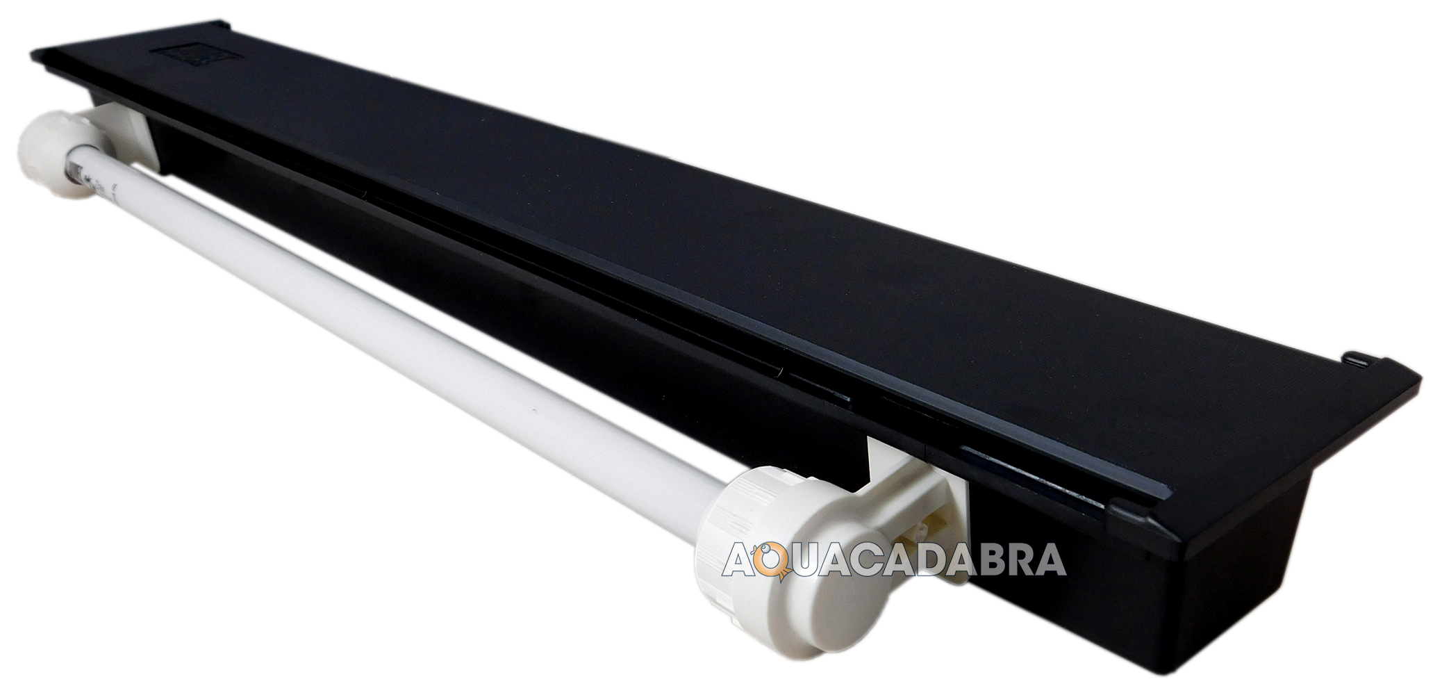 This is a pretty expensive bastard to replace so I'd like to try to diagnose this further, is there anything I can do with just a multimeter? The ballast is probably sealed inside the black box part but I might be able to get to it with some effort.
|
|
#
¿
Mar 15, 2018 11:37
|
|
|
Stabby McDamage posted:On the BLE thing: Looks good, but I'm stupidly disappointed that it just seems to be an Adafruit thing and not a made-in-china-by-the-bucketload thing. It does look like an easy bet...I'm just spoiled on $4 parts. Stabby McDamage posted:I actually have one of that exact thing, but the issues are (a) it goes to sleep and requires a keypress+wait to come back online and reconnect and (b) the form factor doesn't have good tactile feedback to use without looking. If I make one that's powered by the car power, it will power+connect on car start (just like the vehicle bluetooth audio) and run as long as the car is on without a sleep state. Saying that now, I wonder if I could just hack apart one of those buttons to craft it to more ergonomic buttons and junction it to car power, but it would still go to sleep on long drives. Stabby McDamage posted:I'm not a fish expert, but could you just replace it with LED strip? That's what I did with an old LCD monitor with a flourescent backlight -- high density LED strip brought it back to life. Not sure if fish need special wavelengths or something.
|
|
#
¿
Mar 16, 2018 14:49
|
|
|
I'm logging some data with an ESP8266 and I'm having some issues with the BME280 sensor. I'm sampling from it once every minute and from time to time it freaks out and returns ridiculous values. It's not always the same but usually around -30C. Humidity is probably ok but is being affected by the temp, pressure is way off too. The actual temperature should never be -30C so I could easily filter out these values, but still it's bothering me. It could be just the chinesium sensor but I want to make sure I didn't mess up myself.
|
|
#
¿
Jun 7, 2018 20:58
|
|
|
ate all the Oreos posted:How are you doing the sampling? Are you using SPI or I2C? The device has a couple of modes, the "forced" mode that just takes a sample whenever you ask it to and the "normal" mode that samples periodically and just makes the most recent sample available. Maybe try a different mode and see if you get a different result? If you're reading all the registers at once in a single sequential read operation, you could check to see if the chip ID ever comes back garbled, or if the status register says the device is doing something when the data indicates bad values. You could also try sending the reset code and waiting a second for it to reset before taking a sample, just to see if the device is getting into some weird internal state over time. JawnV6 posted:I think Sagebrush and Oreos are correct. But just for my curiosity, what's "-30C" look like on the wire before any of your conditioning or adjustment?
|
|
#
¿
Jun 13, 2018 00:23
|
|
|
I too doubt the microwave has an RTC battery. No idea what it could actually be though other than some general wonkiness in the circuit.mobby_6kl posted:Thanks. It's hooked up with I2C. I think it's sampling in normal mode, at least I don't remember switching it. I'd probably need to review the code as it's been a while, as well as investigate the library which is supposedly a wrapper over Bosch reference implementation. Unfortunately of course this hides a lot of what's really going on there from me, so this might be a great opportunity to finally bust out my ebay logic analyzer. Hopefully I'll have a bit more time this week to mess with this so I'll post an update. All right, too me a while but I finally got to use my $5 logic analyzer. I read from the sensor every minute and this is what it looks like on the wire:  Uh-huh well I couldn't quite figure out what's going on there yet so I clearly need to read the data sheet some more. One challenge though is that this is an intermittent problem so I need to capture a ton of these and then correlate them with the data I get. Is there any way to get the Saleae analyzer to pause the capture until the next trigger?
|
|
#
¿
Jul 11, 2018 21:09
|
|
|
I just received a usb 5V->12V boost converter to charge my tablet off my non-USB-C powerbank. It's looks like this one: https://www.ebay.com/itm/USB-DC-5V-...ksid=m570.l1313 Supposedly it's up to 0.8-1A @ 12V which is below what the stock charger does but should've been good enough to slowly top up the battery. But actually it only supplies ~180mA when the tablet is in sleep mode and charging, and goes to just above 200 when it's on before it starts buzzing and shuts off. I popped the cover off and part of the coil was broken off. I didn't see the missing piece anywhere so I guess it was already missing. Could this be causing the issue? I don't really know enough about how it works to know.  The chip is Feeling Technology FP6293: http://www.feeling-tech.com.tw/km-master/ezcatfiles/cust/img/img/24/fp6293v062.pdf The chip has a configurable current limit at I=48000/R3, which is 41k so 1.17A. What is not really clear is if this limits the input current or the output, but even if it's on input, it should be ouptutting ~0.5A rather than less than 0.2.
|
|
#
¿
Jul 26, 2018 09:25
|
|
|
ate all the Oreos posted:The chipped inductor will affect it a bit but it shouldn't be enough to kill it. The fact that it's buzzing is real suspicious though, it supposedly runs at 1 MHz which should be miles away from the audible range... ate all the Oreos posted:Ok so I noticed it says in that datasheet that the current limit function is limiting switch current, which is the peak current that runs through the switching element. That's very different from the output current, and varies based on the topology of the circuit. In the case of a common MC34063A configured in boost mode, the formula relating switch current to output current is: I don't have any tools more advanced than a multimeter, but I did just get a bunch of COB LEDs (from eby of course) and hooking this up to the smallest drew about 450mA, ~570mA with the medium and 650mA with the largest board. No buzzing or any other weirdness, so this is pretty cool as it's in the same ballpark you calculated. Connecting it back to the tablet results in the same fail though. With it on, the current seems to first jump to around 1A before quickly falling to about 200mA (based on just watching the multimeter refresh) and starting to buzz after about 20-30secs, dropping the current to about 20mA but voltage up to 12.9V (from 12.1 or so). Okay so maybe the tablet wants to draw much more current and freaks out when it can't get it... but then when it's in sleep mode, it just goes directly to 170mA and is perfectly stable for hours. Oh well, maybe I've just been had time to throw a few bucks at another model and see if it works better.
mobby_6kl fucked around with this message at 16:51 on Jul 26, 2018 |
|
#
¿
Jul 26, 2018 16:47
|
|

|

|
| # ¿ May 5, 2024 16:56 |
|
|
Foxfire_ posted:What are you using on the USB end? <= USB2 is only rated to deliver 100mA baseline, extendable up to 500mA if the device asks and receives permission to do so. ate all the Oreos posted:They mentioned a "non-USB-C powerbank" so I assume your usual battery pack with USB-A ports. Power banks usually at least claim to support 2.1A, though in my experience it's unlikely it can actually output that much unless it's a nicer one. I haven't measured it but it's pretty skookum and charges stuff very quickly. I'll see if I can test it somehow later tonight.
|
|
#
¿
Jul 27, 2018 19:49
|
|