


|
I've decided to fabricate my own ipod charging/line out dock to be hard wired into my car stereo. It will use the line out from the ipod connector to go to the stereo, and will use a switched circuit to control charging so it isn't being charged when not needed, theoretically preserving the battery for a while longer. I wanted to clarify some really basic stuff before I turn my ipod into a paperweight. I was planning on using a hacked up usb cable which has four conductors. Conductors 1 and 2 would be L(+) and R(+) respectively. Conductor 3 would be DC(+) to be fed from a hacked 12v car charger. I guess the question is can all these be tied to a common ground? Also, the way I am reading the pinout (#27), will I need to do this resistor tomfoolery to charge the ipod (this is the newest ipod classic 80gig), or is there a better way. I'm not sure of the charger output voltage until I rip it open. 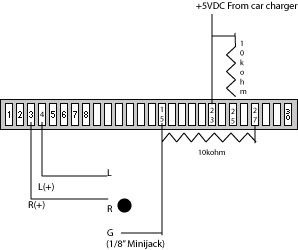 pinouts.ru posted:1 GND Ground (-), internaly connected with Pin 2 on iPod motherboard SuicidalSmurf fucked around with this message at 09:25 on Feb 6, 2008 |
 #
¿
Feb 6, 2008 08:25
#
¿
Feb 6, 2008 08:25
|
|


|

|
| # ¿ May 4, 2024 01:19 |
|
|
Another electronics 101 question. I need to pick up a theory book. I remember what it is that I want, but how to get it done is a mystery to me. I'm not even sure which type of transistors I want to use, I just want to throw a circuit together and have a work. Understanding how it works would be an added bonus. I want to set up a logic gate. I have a momentary push button, B1, that I want to toggle a power source (+12vdc). So, on button press.. if theCircuit = 0 then turn it on if theCircuit = 1 then turn it off If anyone has an easy to understand guide on this stuff that would be great, but I'm a little over my head.
|
|
#
¿
Feb 6, 2008 23:34
|
|
|
I need the latter, push button for a moment, power goes on. Push button again, power off. If it's gonna take 20 transistors then the hell with it, I'll use a regular switch. I won't learn as much, but I won't want to kill myself either.
|
|
#
¿
Feb 7, 2008 05:46
|
|
|
clredwolf posted:Seriously, 74LS109 T-flip flop. 50 cents and it does exactly what you need without the muss and fuss of dozens of transistors. Looking at the specs for this chip on digikey, it appears the supply voltage is between 4.75-5.25v. This will be switching 12vdc. Is there a similar chip with higher voltage capabilities or am I missing something?
|
|
#
¿
Feb 7, 2008 23:55
|
|
|
SnoPuppy posted:Forgive me if this seems like an obviously dumb suggestion, but why not just use a SPDT push button with an "alternate" or "on-on" or "locking" action instead of momentary? Just connect one side to ground and the other to your 12 volts (make sure it is a break before make switch). That was the solution I ultimately arrived at, but I was initially looking at some fancy-pants implimentation.
|
|
#
¿
Feb 8, 2008 01:54
|
|
|

|
| # ¿ May 4, 2024 01:19 |
|
|
I took some electronics classes in high school and have forgotten mostly everything since then. Anyway, I am installing an Android car stereo in a car with a pushbutton ignition. When the ignition is turned off, the car is fully powered off, and I cannot go to the "accessory" mode of the ignition without the unit powering off. I want to keep power on the ACC wire of the stereo for a few seconds after the car is keyed off so the unit doesn't shut down. I've seen circuits that use a capacitor and relay connected to the battery wire to maintain power for a set amount of time. Is it possible to simplify this a bit and use a capacitor and diode inline on the ACC wire to get a few seconds of voltage on this input?
|
|
#
¿
Mar 13, 2015 08:57
|
|