


|
Hey anyone willing to give me a hand with a circuit. It's called a negative impedence converter, it's built around op amps and you use it to make filters. The idea is that the effective input impedence will be -Z, where Z is whatever you connect between the inverting input and ground. It looks very much like a typical op-amp current source, but the positive feedback is wierd. feel free to use a lot of profanity if you want. 
Zaxxon fucked around with this message at 18:40 on Feb 6, 2008 |
 #
¿
Feb 6, 2008 18:38
#
¿
Feb 6, 2008 18:38
|
|


|

|
| # ¿ May 4, 2024 03:09 |
|
|
mtwieg posted:Think about it this way. Define impedance as V/I. Assuming the op amp is not saturated, the voltage at the noninverting input (Vin) will equal the voltage at the inverting input. So the current across Rz will be Vin/Rz, as will the current across the negative feedback resistor (call it R2). In this sense it pretty much is a current current source. The output of the op amp will be Vin(1 + R2/Rz). Therefore the current across the positive feedback resistor (call it R1) will be [Vin(1 + R2/Rz) - Vin]/R1, or -(Vin/Rz)(R2/R1). This current is negative because it's flowing into the voltage source. Normally this circuit will be built with R2 = R1, so it simplifies to I = -Vin/Rz. Do some algebra and you get -Rz = Vin/I. Therefore, since we defined impedance as V/I, Zin = -Rz. Bam. Ah ha, that makes sense. In my head I was thinking of the op amp input as sourcing a current, but they can't do that. Whoops.
|
|
#
¿
Feb 7, 2008 19:02
|
|
|
sithael posted:My pack of linear ics had 11 apple II sound chips. I wish i knew how to use them. I also got 26 hex inverters which make easy oscillators. poo poo I'll take them off your hands. I can figure out how to work them.
|
|
#
¿
Feb 15, 2008 21:23
|
|
|
Innominate posted:Well what level are you at? The cheapest, fastest, simplest way to get into microcontroller development is probably the picaxe. They're rather slow to the point of often being underpowered, but have free programming software, a trivial to build programming interface, and the chips can be had for just a few dollars. a nicer thing might be the AVR butterfly. It's 20 bucks, plus the cost of a serial cable and a little work to program it. But you get an ATMega chip programable in C.
|
|
#
¿
Apr 22, 2008 17:39
|
|
|
Can someone help me find some components to order. I need to get some connecters of a specific type. If anyone has an STK500 they know that connector which you press onto the end of a piece of ribbon cable. I'd like to get a bunch of those in various sizes. As well there is a type which works the same way, but the connecter at the end fits into a DIP socket. What are those things called?
|
|
#
¿
May 14, 2008 02:01
|
|
|
babyeatingpsychopath posted:I think your "connector you press onto the end of a piece of ribbon cable" is a standard .1" header block, and you can get them in sizes from 1x1 to 60x2. My local electronics store has a whole rack of them. That will work but it's not what I'm thinking of. What you are suggesting will take a while and it's frankly not something I'm prepared to spend a lot of time with. The thing I'm thinking of is the same size as a header block, but it's end has wierd fork shaped connections and a back plate that you crimp onto the ribbon cable with a pair of pliers.
|
|
#
¿
May 14, 2008 23:38
|
|
|
Fatal posted:I'm still waiting for some components (so I can test this question) but I was wondering what would happen if I only attach a positive voltage source to an opamp Vcc (+) and nothing to the negative input? Would it only show the positive part of the output signal, nothing at all, or blow up? As a side question, any elegant way of producing a negative voltage source besides putting two batteries in series and grounding the junction point? nothing will happen if you don't put anything into the negative part. You would want to at least ground it. Zaxxon posted:If anyone has an STK500 they know that connector which you press onto the end of a piece of ribbon cable. I'd like to get a bunch of those in various sizes. As well there is a type which works the same way, but the connecter at the end fits into a DIP socket. What are those things called? I found this out. They are called IDC connectors. Now to wade through a parts house's unfathomable nomenclature to get the sizes and styles I need!
|
|
#
¿
May 15, 2008 02:33
|
|
|
hey guys I'm trying to find a specific type of connector but I don't know what it's called. It's similar to an IDC connector, but it fits on slightly larger wire, closer to hook-up wires than ribbon cable or wire-wrap stuff. It's usually used in pairs, and it has what looks like a normal female header on the end, the end fits snugly over normal header pins. the STK500 comes with a bunch of these little paired wires with this kind of connector. here are some pictures:    anyone know what it's called?
|
|
#
¿
Jan 7, 2009 09:32
|
|
|
mtwieg posted:ugh, searching for connectors is such a bitch. Makes having a catalog full of pictures worthwhile. I looked for the same exact thing (and also for the stk500) a while back. The general name for those types of connectors are rectangular. It's female, or rather a receptacle. And it's free hanging. The pitch is 0.1". it is such a bitch! And it's one of those things that seems like there would only be a few real standards in. I mean everything has the same kind of header pins, so why is is so drat hard to find connectors for them? those seem like they will do the trick. Don't let anyone tell you you aren't a hero. But yes searching for connectors is a colossal pain. I'm going to try my local salvage store (MC Howards for any electro goons in austin,) as they tend to have a fair amount of varied connectors or cables with connectors attached.
|
|
#
¿
Jan 8, 2009 04:51
|
|
|
mtwieg posted:here are some without the locking mechanism. Now that I think about it the locking mechanism might make it impossible to connect two of them next to each other, so you should go with these simple ones. I grabbed a bunch and some digital pots. also the no lead versions are a bit cheaper.
|
|
#
¿
Jan 9, 2009 01:33
|
|
|
Metajo Cum Dumpster posted:Has anyone ordered from Adafruit before? They have a nice Arduino starter kit bundle that goes with this Arduino beginner's tutorial. yeah I got some spoke POV kits and a TVBegone. They are cool.
|
|
#
¿
Jan 12, 2009 18:49
|
|
|
Colin Ex Machina posted:I'm putting together a power supply with three different voltages out -- unimpeded (at 9v), 5v (brought down via a 7805 stage), and an adjustable (brought down by a fancy robotics adjustable regulator). It's coming from a 9v wall wart. just put a cap between vout and ground for each of them. That is what one normally does with bypass caps.
|
|
#
¿
Jan 14, 2009 17:42
|
|
|
mtwieg posted:Keep in mind that wallwart supplies are almost never actually regulated. Their voltages depend heavily on the load. Make sure that with no load its voltage isn't more than the arduino can handle. the arduino has a regulator in it I believe, it is a 5v device and accepts a 9v wall wart.
|
|
#
¿
Jan 14, 2009 20:30
|
|
|
mtwieg posted:here are some without the locking mechanism. Now that I think about it the locking mechanism might make it impossible to connect two of them next to each other, so you should go with these simple ones. just a word to everyone else as I had to figure it out the hard way. The way these things work is you solder the wire onto the end of the silver thing sticking out the back, then you bend in all the little parts that stick up and then cram the metal part into the rectangular housing until it clicks in, then you have a connector. I had to break a pair of them before I figured that out. The datasheet was no help.
|
|
#
¿
Jan 15, 2009 08:12
|
|
|
turbo sex bat 4000 posted:I'm pretty sure there is a crimping tool for those. Those fingers at the end crimp onto the insulation and the other bit onto the conductor, then you slide the whole thing in. well it's all quite doable with solder and fingers, so I might stick with that.
|
|
#
¿
Jan 16, 2009 21:45
|
|
|
Ham Session posted:has anyone used any of these XMOS micro controllers I want to start playing with them and would like to know how good they are. those seem Pretty cool. I'm curious about them myself.
|
|
#
¿
Jan 16, 2009 21:50
|
|
|
anyone here ever work with solar cells? I'm having a hell of a time trying to connect them together. Solder won't stick to them and it's hard as poo poo to get them to do anything without breaking.
|
|
#
¿
Jan 19, 2009 17:41
|
|
|
ok this has been bothering me for a while, but do we have any kind of good tutorial on soldering Iron maintinance. My Iron gets this horrible black poo poo all over it and refuses to have anything stick to it really fast. I keep it tinned when it's off and I clean it frequently, but I end up having to literally scour it between uses, and even then I can only use it for like 1 hour before it becomes completely crap.
|
|
#
¿
Jan 23, 2009 18:01
|
|
|
mtwieg posted:is it black like melted plastic, or is it semitransparent brown goo? if the latter, it's probably excess rosin. it's black and brown, so I'm guessing the rosin. And yeah I use a sponge.
|
|
#
¿
Jan 23, 2009 20:39
|
|
|
ValhallaSmith posted:What have you been scouring it with? plain copper pan scrubber.
|
|
#
¿
Jan 23, 2009 22:07
|
|
|
I have 2 irons. Both of them sub 100 but both somewhat temp controlled (dials with 1-2-3-4 on them) both do the same drat thing. My friend eric uses a cheap $25 iron and it never seems to give him any poo poo, which makes me think I'm doing something wrong with them. I tend to only have to turn the heat about halfway up to get the solder a meltin'. But that starts the iron crappin out.
|
|
#
¿
Jan 24, 2009 03:20
|
|
|
Bexx posted:How old is the tip? How often do you use it? Are you actually scouring it with copper? Or just lightly rubbing it down? Where is the black? On the heating surface or above it? one Iron I have had for about a year and the other is brand new, the black is on the heating surface. though it's more brown close to the end. Normally when using the Iron I heat it up and let it sit. Then I melt a little solder on it to see if it's hot enough, after that I wipe the iron off on a damp sponge and then I solder things, wiping the Iron down a bit when I'm not using it directly (usually once every couple of minutes.) Then when I'm going to put it up, I melt a little blob of solder to the end and shut it down. After a couple of sessions, the black crap has build up so much that nothing will stick to it. So I take the copper pan thing (I have one only to this purpose, never used for anything else) and scrape the crap off. That gets it right to use again until about a year.
|
|
#
¿
Jan 24, 2009 04:12
|
|
|
ANIME AKBAR posted:well first of all this device comes in an MSOP package which is much smaller than SOIC. It's feasible to dead bug solder it but it's quite difficult and really requires the right type of wire (Teflon insulation). It will be fragile and a pain in the rear end. You can find breakout boards made for this kind of stuff. They're pcbs with surface mount footprints attached to through holes that are easy to solder to. Finding one for an MSOP package might be hard though. A friend of mine once found the website of a place that specialized in breakout boards. I'll try to get it from him. digikey has an MSOP to SIP converter. But it seems to be 8 pins only. http://search.digikey.com/scripts/DkSearch/dksus.dll?Detail&name=33108CA-ND
|
|
#
¿
Jan 25, 2009 19:20
|
|
|
ANIME AKBAR posted:that's a rather unusual implementation of the 555, though I don't see why it wouldn't work. if your willing to do some somewhat delicate biasing you could also use the grounding capacitor of the astable 555 and a comparator.
|
|
#
¿
Jan 27, 2009 19:57
|
|
|
Snaily posted:Any hope for a schematic of this? uh maybe when I get home. I can give something you can plug into the java circuit simulator to see how it goes though. here is the circuit sim code (just pull up file import and paste this in) here is the applet circuit sim: http://www.falstad.com/circuit/ code:However you do get some bonuses. One is that you can voltage control your PWM. The other is that you only need to use one of the 555's resistors to control it's frequency. As well your output voltages can be conrolled by the op amps power rails. I also want to give the caveat that I have never tried this with real parts, it's just a design similar to anlog synth PWM systems, where you use a sawtooth wave and a comparator.
|
|
#
¿
Jan 27, 2009 21:46
|
|
|
Snaily posted:This is the best thread. Thanks. did that circuit sim stuff help at all?
|
|
#
¿
Jan 29, 2009 18:21
|
|
|
if your town has an electronics surplus type store you can probably get them at something like $0.35. See if you can find one.
|
|
#
¿
Feb 18, 2009 03:56
|
|
|
clredwolf posted:East coast is a bit sparse on surplus electronics stores (I am so jealous of you Californians discovering electronics!). May be something around though, I'll take a look... I'm down in austin so we get a huge pile of runoff from Texas instruments and freescale/motorola.
|
|
#
¿
Feb 19, 2009 22:58
|
|
|
ANIME AKBAR posted:Whatever you get, just make sure it has replaceable tips available. There are a couple stations on sparkfun, and neither of them are those brands, but I trust sparkfun pretty well to sell good stuff. They have pretty much everything a hobbyist would need. I (after my posted about soldering woes) nabbed the 906 hot air rework station and soldering iron, it's been good to me so far(as I have kept the tip well tinned and cleaned as advised.) I haven't got a chance to test the hot air yet but the iron seems solid.
|
|
#
¿
Feb 23, 2009 23:54
|
|
|
ANIME AKBAR posted:And none of this really addresses my original question, which is how I could interface a device to an existing phone line on the hardware level. I'm open to other means of transmitting data, but a few acronyms don't help me. I need to know more specifically how the interface might work. I might be misunderstanding what you are asking for here, so excuse me if this is beside the point. If all you want to do is be able to listen and send in parallel with the original phone line I think you can just patch onto the same line as the phone (that is literally just wire your cable and ground to the same wires as the original.) You will have to find out about the levels and such involved, but more than one reciever/transmitter can be tied into one phone line. I just remember being a kid, and we had 2 phones and one line, so if you picked up both phones they would both be connected to both eachother and the outside caller.
|
|
#
¿
Feb 24, 2009 06:42
|
|
|
why the hell are crimping tools so drat expensive? Anyone have a clue?
|
|
#
¿
Apr 15, 2009 23:46
|
|
|
BattleMaster posted:I've never ordered from Mouser because their shipping costs to Canada is kind of high, but I am extremely impressed with Digikey. For only 8 dollars they ship it from the US to my door in 2 days with no customs bullshit. mouser is top tier if you are in texas. I order from them all the time, I usually pay the lowest FedEx rate and get the product the next day.
|
|
#
¿
Jun 11, 2009 21:00
|
|
|
Scarboy posted:Does anyone know if there is a way to do what an analog switch (4066) does on a MCU or an FPGA (excessive!)? I have a circuit that uses 8 of these chips but they take up a lot of board space and end up costing more than a MCU would cost. I would obviously need a lot of pins on the chip to have equal functionality, but I have some ideas for things I can do to simplify the design if I can somehow do this on an MCU. what exactly are you doing with the 4066? for the most part this is impossible, in some cases it's possible. Zaxxon fucked around with this message at 02:50 on Jun 25, 2009 |
|
#
¿
Jun 25, 2009 02:44
|
|
|
any of you guys ever messed with wire wrapping? A lot of projects I've been doing lately are just a microcontroller and a few other chips. WireWrap seems pretty cool for putting stuff like that together.
|
|
#
¿
Jun 25, 2009 21:57
|
|
|
any of Yall use the mentor graphics "PADS" suite. I'm trying to make some part types and I'm having trouble with anything that's board layout isn't a pattern the wizard can make (QFNs DIPs or whatever.)
|
|
#
¿
Oct 3, 2009 22:17
|
|
|
CapnBry posted:Does anyone have any tips on how build prototypes on perfboard? I'm having a lot of fun designing simple circuits but then putting them together is like 2 bitches in a bitch boat. I use the sort of perfboard that doesn't have any of the holes connected because I'd like to keep my designs small (like a simple 555 PWM doesn't take a 5"x5" square). so there are a few things. First, use smaller wire. Wire wrap wire works pretty well it is typically 28-30 gauge and it kinda holds itself flat, so you don't have to tape it. You can sometimes find multicolor packs of it. It has the problem that you have to strip it using a wire wrap tool (most regular strippers will just cut it cause it's too thin.) next thing you want to do is get the kind of perfboard that has plated pads around the holes. It's a little bit more expensive but it's well worth it. You can just solder your component on, then wire it up. Also you can lay a cut lead across multiple holes then solder it down to the holes to make a little bus for attaching a bunch of different things to the same pin (useful for power and ground.) Even better than wire wrap wire is a particular type of magnet wire. Magnet wire tends to be less flexible and more "sticky" than wire wrap, but most kinds are a bitch to strip and tin, especially the normal kind you find which is enamel insulated. you have to kinda scrape off the enamel with shears then tin the little exposed bits. However some magnet wire is insulated with this polyester stuff called "POLYTHERMALEZEtm" that poo poo is awesome. Basically the heat of the solder and the flux will melt the insulation off, tinning it without you having to strip it at all. The big problems with that stuff is it gets harder to melt the thicker the wire is, It's hard to find in anything less than $70 1lb spindles (that is enough to do a serious poo poo ton of perfboarding,) and it only seems to come in one color, this sort of red-orange thinner wires look more orange, thicker ones more red. oh yeah. Also, you probably already know this. But wire up one component at a time and verify your soldering with a voltmeter beep test. If you can, and what I like to do is wire up one component and then test it electronically. Like right now I'm working on a project involving an atmega162, so the first thing I did was wire up the micro controller, the power, and the ISP header. Then tried to program it. Next up I'll be doing the serial port. Then 1 of the two sound chips (I'm wiring up a controller for some old ATARI sound chips.) Zaxxon fucked around with this message at 20:02 on Sep 10, 2010 |
|
#
¿
Sep 10, 2010 19:51
|
|
|
Hillridge posted:Wire wrap wire is the way to go unless you need a lot of power for something. For most of my PCB rework I use 30 AWG with Teflon insulation. I'd recommend getting this type of insulation as it does not melt when soldering. That way you can trim the wire to the exact length you need, strip the ends, and not worry about insulation peeling back/melting as you try to solder it. this is very true. When I was first turned on to wire wrap stuff I got some poo poo with plastic insulation that melted away really quickly. and left a black mess with bits of exposed wire. With the polythermaleze magnet stuff it takes a bit for the stuff to melt away, so I find I have no trouble with it melting too far while actually soldering.
|
|
#
¿
Sep 10, 2010 20:05
|
|
|
I wanted to show off some of the perfboarding stuff I was talking about. here is my latest board: top: 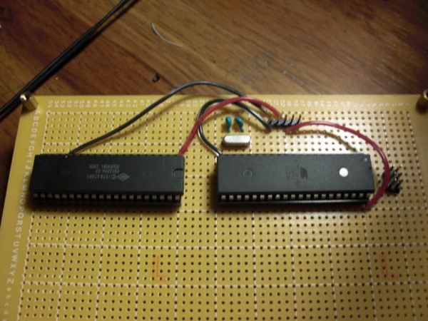 it's not too exciting, just 2 chips and a crystal, the pins on the right side are an AVR ISP header, and the pins on top are for an FTDI USB to TTL cable. Those black and red wires are power and ground. originally I was just alligator clipping them to my bench supply to test things, then I started running everything off the USB power. Tommorow I plan on wiring in the actual power supply bottom: 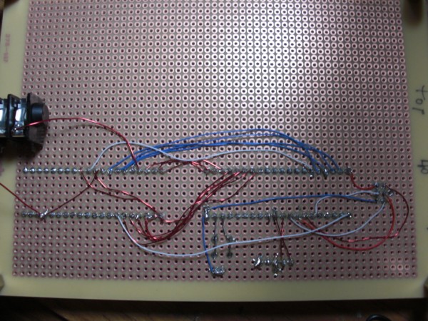 Here is where you can see the virtues of small wire! The blue and white lines are 28 gague wire wrap wire, and the shiny coppery stuff is the polythermaleze magnet wire I was talking about. Wiring up the data bus of that pokey chip took like 8 minutes using the magnet wire. You can't see it to well, but in that picture you will notice that the wires on the top side of the board aren't soldered into a pad, that is because I'll be clipping them off when the power supply gets in. 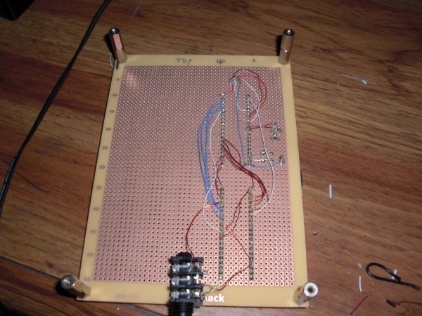 if you will notice the sharpie writing on the top, I've found I often turn the boards upside down, or forget the fact that the chips are flipped over, so I like to write a little guide reminding me of which one is pin 1 and which is pin 40. hacky output jack: 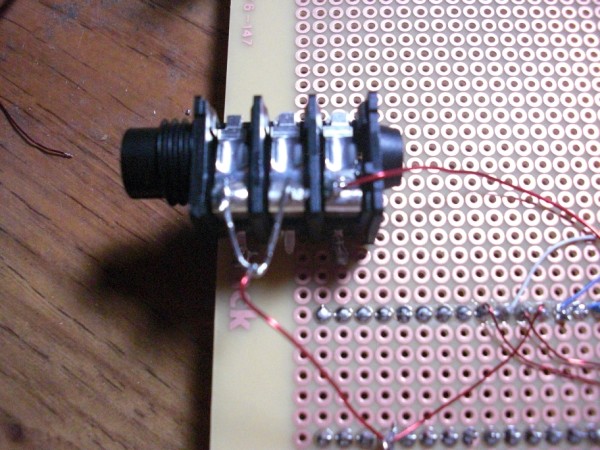 I'm showing this ugly kludge to remind people that it's ok to hack a little bit on perfboard designs. I didn't have a 1/4" jack that would fit properly on the board so I bent the legs on that one and soldered them "surface mount" style, I'm glad I had copper pads on the bottom of that board to do that with. Even the stupid "radio shack" logo was copper, so I soldered some poo poo to it! Then I just soldered the wires to where they needed to go and bent one of the capacitors clipped leads to connect the contact that would normally go to the middle part of a balanced cable to ground. Tomorrow I'll be adding a power supply and then it will be time to get the firmwares working. Once that happens i'll probably add a second pokey chip and a MIDI interface. Also since the board I'm using is nice and big if I need to add buffer amps or something to the output, there is still plenty of room.
|
|
#
¿
Sep 14, 2010 08:48
|
|
|
CapnBry posted:I also wish that there was a type of store like a Home Depot except with inventory like Mouser or DigiKey. I'm ordering like a package a week from these places; I'm pretty sure they're going to assign me an account representative any day now. what city are you in?
|
|
#
¿
Sep 14, 2010 08:50
|
|
|

|
| # ¿ May 4, 2024 03:09 |
|
|
Delta-Wye posted:Cool, but uh, what does it do? oh sorry. The chip on top is an atMEGA162, which is an AVR microcontroller. I like the 162s because they have 2 separate USARTS, one for regular serial input and output, the other for MIDI. The other chip is an atari POKEY the sound chip from an old atari. I'm going to have the microcontroller use the soundchip to make atari sounds. I was given a crapton of old soundchips by a friends old boss who ran a pinball repair shop.
|
|
#
¿
Sep 14, 2010 16:23
|
|