


|
I approve of this thread! I currently work as an R&D Electrical Engineer, so I'm sure I'll be following this thread. It can not be overemphasized how much of a difference a quality soldering iron makes when working on stuff. That $20 radioshack iron will probably solder two wires together, but there is no way you're going to solder fine pitch surface mount parts with it. If you do a lot of work with surface mount components then having a hot air gun also works well. Also, get a little squirt bottle full of flux and apply it liberally to things you wish to solder. Do that and use leaded solder (the lead free stuff sucks) and things will go much easier.
|
 #
¿
Jan 8, 2008 17:31
#
¿
Jan 8, 2008 17:31
|
|


|

|
| # ¿ May 1, 2024 01:08 |
|
|
Circumcision Hater posted:Thanks for the info. I'm getting tired of buying new tips and irons every few months. I'm also interested in what other tools are needed for a good hobbyist setup. Heat gun and a big old pile of heatshrink tubing are definitely on my list of things to get. Should I look for anything in particular in a heat gun? Are temperature/CFM/BTUs/etc important or will whatever's in stock at the local industrial electronics store be fine? A good thing to do to keep your iron tips fresh and shiny is to "tin" them before turning the iron off. Basically cover the whole tip with a big glob of solder and let it cool on there. When you need to use the iron again, just let it heat up and wipe off the solder on the sponge. By heat gun I actually meant one of these guys:  This thing is essential in reworking surface mount parts since it allows you to heat up the whole part at once. You can pop off a chip with dozens of pins in a matter of seconds, whereas I don't think you'd ever get it off with an iron. They also have a tip that fits over the end of the wand to reduce the airflow to a small tube rather than the big 1" or so opening, which is ideal for resistors and other small parts. Cuw posted:And if you are going to be soldering lots of surface mount parts you might want to look into getting an air solder station instead of a iron based one. They use a solder paste instead of solder wire and a really fine nozeled hot air gun and by god do they make soldering .22" pitch parts easy. They really complement a nice soldering iron more than replace it since you are going to need the iron for larger parts, you can't really use paste to solder wires together, or for through hole parts. This works, but I solder parts almost exclusively with an iron, even the fine pitch stuff (there is a neat trick that involves dragging the iron along the pins). Have you ever looked at solder paste under a microscope? It's tons of tiny solder balls suspended in flux and looks really cool:  (Click for huge) I have never needed a vacuum rework station for anything, but they are neat. You can save your money and buy a small manual solder sucker and a package of solder wick instead.:   Flux is your friend. It makes everything solder related easier. The type I use around the lab is Kester 959 low residue no-clean flux. It's designed for wave soldering machines, but it works great for doing stuff by hand too. I've gotten it all over my hands when I'm working and it has yet to hurt me. I just wash up when I'm done. Don't inhale when the iron vaporizes it though. Edit - From their site: 959 No-Clean Alcohol-Based | Fluxes Kester 959 is a no-clean, non-corrosive, halogen free liquid flux that is designed for the wave soldering of conventional and surface mount circuit board assemblies. Kester 959 was developed to minimize the formation of micro-solderballs during wave soldering operations. This flux contains a small percentage of rosin (1%), which improves solderability, heat stability and surface insulation resistance. Kester 959 offers the best wetting and the shiniest solder joints of any no-clean, solvent-based chemistry. Kester 959 leaves evenly distributed residues for the best cosmetic appearance. This may be a lot for someone just getting started. I went for years using a soldering gun (huge compared to an iron) on through hole projects. Hillridge fucked around with this message at 16:52 on Jan 9, 2008 |
|
#
¿
Jan 9, 2008 16:22
|
|
|
Kudosx posted:I'll agree with this. I burned the living crap out of myself the first time I tried to solder something. In my CCNA/A+ class in High School our teacher gave us a little soldering intro lesson, and we made robots that walked around each other via I.R.'s or some crap Don't scratch your face while holding the iron. I got a nice burn on my nose from doing that. Also, don't solder barefoot. One drip on your foot and you learn that lesson.
|
|
#
¿
Jan 9, 2008 17:21
|
|
|
joebuddah posted:Could somebody tell me a good book to learn plc programing? I'm probably going to buy a DL06 from automationdirect.com. I recently got some nifty automation devices for helping a friend tear down one of the machines at his job as they were selling it for scrap metal. I tried to PM you, but I guess you don't have that. I need to look up the model (I think it's an Allen Bradley SLC 500 5/03 CPU), but I have a PLC and Backplane gathering dust at home if you're interested. I already sold off all of the IO modules so I have no use for the CPU module and backplane. It looks similar to this, except my backplane has around 11 slots: http://i11.ebayimg.com/06/i/000/cd/33/0129_1.JPG Let me know if you can use it. I'd be happy to sell it for cheap and reclaim some space in my junk room.
|
|
#
¿
Jan 9, 2008 18:57
|
|
|
SkunkDuster posted:
It indicates a temperature coefficient of 25ppm. Usually resistors with more than 4 bands are precision resistors with the extra bands used for the extra significant digits. On your resistor the 4th band is clearly a tolerance band (special colors), so the 5th band gives the temperature coefficient (how tolerant the resistor is to temperature changes). The parts per million (ppm) unit can be a little confusing, but the way it works is like this: In the case of your resistor, for every �C (or K, take your pick) increase, the tolerance of the resistor becomes 25/1,000,000 worse. So if you change the temperature by 40�C you'd get an additional 0.1% variation in the resistance. Hillridge fucked around with this message at 21:12 on Jan 9, 2008 |
|
#
¿
Jan 9, 2008 21:04
|
|

|
I can see that maybe working if the whole moving assembly is massless. Here's something that may not be all that useful, but it is interesting: LEDs work in both directions. If you take two identical LEDs and power one of them then hold the other one next to the lit one, a small current will be induced on the unlit LED. Try it out.
|
|
#
¿
Jan 16, 2008 17:48
|
|
|
BeefofAges posted:You do realize that solar cells are just diodes, right? Yeah, they're made of PN junctions specifically designed for solar wavelengths. Using LEDs like this is a way of making a very cheap optical switch that only works at the wavelength of the LED and won't be affected by ambient light. They have to be right on top of each other to get any meaningful current out though.
|
|
#
¿
Jan 17, 2008 14:40
|
|
|
I thought of a good project, though it's legality is dubious. Every FM transmitter (for ipods, etc.) on the market sucks. My theory as to why, is that FCC laws limit the transmit power to something so low a sneeze will cause static. How about we crack open one of these guys and see about boosting the signal power? I think I may have a few at home I bought off Woot. I think this can easily be done by simply adding a tuned antenna, or via the more involved route of actually building an amplifier. Hillridge fucked around with this message at 14:45 on Jan 24, 2008 |
|
#
¿
Jan 24, 2008 14:37
|
|
|
Rather than trying to put together a switcher, have you thought about just buying a power module? Something like this: http://search.digikey.com/scripts/DkSearch/dksus.dll?Detail?name=296-20400-ND It's a switcher with all the support circuitry already on the board. You just need to add a few discretes (cap and a couple voltage setting resistors) and you're good to go. If you go to TI's page you can probably get one as a free sample.
|
|
#
¿
Apr 2, 2008 21:57
|
|
|
The easiest way is just to use a linear regulator (like one in the LM317 family), but you have to remember that linear regulators "burn off" the extra voltage, so they will waste a lot (4/9) of the power in that battery. A switching power supply is ideal for what you want to do. They can be more than 90% efficient, they're just a little harder to design. Usually you can find an example circuit in the datasheet that will do exactly what you want. Look around Microchip's website. Chances are that they will recommend a power supply chip for whatever PIC you are using. Edit: After looking at the datasheet, this PIC has a range of 2.0-5.5V. It also has very low current draw, so you could easily run it off of a couple AA batteries, or even a 3V lithium cell. Hillridge fucked around with this message at 15:36 on Apr 4, 2008 |
|
#
¿
Apr 4, 2008 15:26
|
|
|
I have an electrical question, and I know some electricians read this thread, so this is the best place I could think of to post it. I recently got a new compressor that requires a 240V/15A line. When I moved into my house I needed a new water heater, so I put in a gas one and got rid of the electric one. The way electric is set up in my area, there are 2 meters: 1 for the house, and 1 for just the hot water tank (I guess they are billed at different rates). Since I had my tank removed, I also had this second meter pulled. So this left me with an unpowered 30A breaker connected to 10 gauge, 2 conductor wire with no ground that went from my panel to just about where I put my new compressor. Here's how I was thinking of modifying my circuit so that I can use this existing run of wire to power the compressor: Remove wire from 30A special panel breaker and move to 20A breaker on main panel. Attach other end to compressor. ground compressor to ground wire running in conduit in garage. 10 gauge wire should be more than enough for the current, but the grounding issues are what worry me. Here's a couple quick sketches: Before:  After: 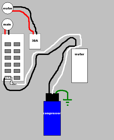 I'd like to know if it is code to do it this way, or what I would need to do to make it code legal. If I had the access I'd just run a new line of 10/2 w/ground, but it goes across a finished ceiling so I'm trying to reuse existing wiring.
|
|
#
¿
Apr 7, 2008 15:48
|
|
|
Yeah, it's just there for protection, and to define the requirements of the driver circuit. quote:The 7407 buffer used to drive the darlington may be replaced with any high-voltage open collector chip that can sink at least 10 milliamps. So long as your driver meets this requirement you should be fine.
|
|
#
¿
Apr 9, 2008 15:59
|
|
|
Yeah that resistor divider isn't going to cut it for much. Depending on the impedance of whatever circuit you are powering with it, those voltages could be quite variable. Other than building a series of switchers to get the voltages you want, you'll be hard pressed to find something that can fit in the space of 6 AAs. I would just use an old PC power supply. You'll get the most common voltages needed (3.3, 5, 12, etc.) and have plenty of current. If you need more voltages than provided, add some linear regulators (small voltage drops, lower currents)or switchers to produce those.
|
|
#
¿
Apr 14, 2008 18:41
|
|
|
Keebler posted:This is what I was originally looking at: If you can afford to burn some power, just put a simple 3 terminal regulator in there to drop it to 3.3V. Hand soldering a BGA is a shot in the dark at best, even with hot air. I try to avoid them on boards I design unless it's my only choice, or I need the space. TSOP is no problem, you just need practice. I could solder that TSOP faster than the leaded version so long as I have a good iron and plenty of flux. If you're interested in soldering SMT parts, this guy is spot on in his advice: http://www.youtube.com/watch?v=3NN7UGWYmBY
|
|
#
¿
Aug 10, 2008 21:45
|
|
|
As in under the carpets inside your car, or on the exterior underside of the car? The former should be fine assuming your wires are sized appropriately for the current draw of your amps. The latter is just a bad idea.
|
|
#
¿
Aug 21, 2008 14:44
|
|
|
SecretFire posted:I had to do some soldering earlier today, and every time I picked up the iron my hand was shaking like I'd developed a case of intermittent acute Parkinson's disease. Breathing out seemed to help, but does anyone have any other tips? Relax your grip and don't drink a bunch of caffeine before hand. I have that happen sometimes if I go to solder right after downing a big cup of coffee.
|
|
#
¿
Aug 27, 2008 14:40
|
|
|
Vim Fuego posted:I'm trying to find a replacement for a specific motor- a Mabuchi RF-500TB-14415. I've found sites selling industrial quantities at http://www.dswbrand.com/electromotor.php and at http://www.icphotos.org/photo/RF500TB14415.html. I don't need thousands, I just need one. Can anyone tell me somewhere I could buy a single one of these? You can always pretend to be a company and request to purchase a sample. Sometimes you'll get it for free. This is kind of a douche move though, so use it as a last resort.
|
|
#
¿
Sep 1, 2008 22:26
|
|
|
I code in straight up binary.
|
|
#
¿
Sep 11, 2008 01:43
|
|
|
If you can get your hands on a hot air station, you can take ANYTHING off a SMT board very easily. I've never used the chip quik stuff, so I can't comment on it.
|
|
#
¿
Sep 17, 2008 14:31
|
|
|
tokki g posted:What materials can be used to insulate speaker wire from emi? I have 4ga and 8ga power/speaker wires running near some RCA and I think I'm getting interference from the power wires. You could always try looping the noisy wire through a ferrite. Grounded shielded cable (even at just the intersection point) is also an option.
|
|
#
¿
Sep 26, 2008 03:12
|
|
|
Vaporware posted:I still haven't touched my radio yet, HiroshigeStations, but I am going to give another try to building a FAN5607 LED dimmer. Last time I attempted this I just couldn't get it to work. I think you may have wired up your chip wrong. The datasheet shows a top-down view of the chip with Pin 1(EN) on the top left side. The pins are then numbered counterclockwise. Here's how you should have it (my edits in red):  Click here for the full 1632x1224 image. I believe you need to tie EN high to max the LEDs, though if it has an internal pull-up you may be able to leave it floating. You may have fried the chip, so if you wire it correctly and it still doesn't work that may be the cause.
|
|
#
¿
Sep 26, 2008 03:42
|
|

|
Vaporware posted:I have no doubt I killed that chip. Lucky I planned ahead and bought 5. I need a new soldering iron tip before I try the next one. I can't get good contact with all the corrosion on mine. Steel Wool might fix that tip temporarily. You should get some flux and rosin (cleaner) when you buy the new tips. Also, always tin the tip with fresh solder before turning off the iron.
|
|
#
¿
Sep 26, 2008 15:09
|
|
|
Iout will depend on the value of a resistor you place between the output of this circuit (top of Cout) and the LED. In this case, 20V is your output voltage, so Iout will equal 20V divided by your resistor value (ie a 10K resistor would make it 2mA). How much current do your LEDs require? You can use a switch to change between values of R, or put in a variable resistor. The SW on that chip has to do with it being a switching power supply. Read around page 8 of that data sheet, it explains the way it operates.
|
|
#
¿
Oct 1, 2008 05:48
|
|
|
Yeah that should work. I haven't really had a chance to look at the datasheet to see how much current this can source, so if you use the example schematic, make sure 15mA is enough. Also, make sure the resistor(s) you use are appropriately sized for the power (P=(I^2)*R) going through them.
|
|
#
¿
Oct 1, 2008 21:29
|
|
|
That should work. 12-(3.5*3)=1.5V 1.5V/82ohm ~= 18mA. It's hard to tell where your power and ground are on that picture, so I'm assuming power comes in on the top left and ground is on the bottom right. Eamonn posted:...that I need to use 82 om resistors for each 3 leds in parralel... This is just nitpicky, but you probablty meant that you have sets of 3 LEDs in parallel. The 3 LEDs of each set are in series.
|
|
#
¿
Oct 7, 2008 18:47
|
|
|
Also, adding a few decades of bypass caps (0.01uF, 0.1uF, 1uF) to your IC's VCC pins (VCC->CAP->GND) helps a lot to reduce noise on the supplies.
|
|
#
¿
Oct 23, 2008 20:38
|
|
|
kaptainkaffeine posted:edit today: So I was thinking about it and it occurred to me that a linear pot would not simply have the 'middle' as equal and attenuate either signal when it's turned, but rather would attenuate both signals by half, and when turned would both boost one signal and attenuate the other till one is twice as loud (edit again: twice the voltage, a log taper pot would be twice as loud) and the other is gone. Is this accurate? I'm waiting for parts to come in so I can't test it. Sort of. You're right on the first part. When the pot is in the middle, both signals will have equal strength, but neither will be as loud as it would on its own. When you shift it all the way to one side, one signal will be back to its original volume, and the other will be much quieter. No boosting, you'd need an amplifier for that. Also, are you just using a NES as a case for this project? I remember the NES as only having a mono sound output.
|
|
#
¿
Oct 29, 2008 17:43
|
|
|
FuzzyBuddha posted:Was wondering if someone can help me out with a project I'm working on. I'm trying to take the output of a Garmin eTrex GPS and read the data on an Arduino board. To do that, I'm running (or at least trying to run...) the signal through an RS232 to TTL converter to get the signal "understandable" by the Arduino. The circuit I'm using was one I found while doing a google search, and comes from sodoityourself.com. I use this chip all the time in designs. What voltage level are the signals from the Garmin? For reference, my applications have 3.3V signals coming into the Maxim part. You mentioned the cap between 2 and 16. That's just a cap from V+ to Vcc. I usually have V+ (and V-) through a 0.1uF 50V cap to ground. Here's my typical setup: Hillridge fucked around with this message at 16:29 on Jan 27, 2009 |
|
#
¿
Jan 27, 2009 16:20
|
|

|
That control pad leads me to believe that your heat gun is controlled by some type of micro. It's hard to say without a better look at it, but my guess is that it's controlling the heat via some type of PWM. You may get lucky and be able to adjust this, but more likely you'll have to resort to that dimmer (put it on the line side as mentioned).
|
|
#
¿
Jan 29, 2009 16:41
|
|
|
For any of you who need project enclosures, http://www.polycase.com/ is a great place for them. You can even get them customized and silk screened (probably not worth it unless you are making a lot of something and selling it).
|
|
#
¿
Jan 29, 2009 23:05
|
|
|
Oops, I was thinking backwards. I should have asked what levels your micro wanted. One thing to watch out for, especially this time of year, is ESD. Always ground yourself before handling ICs. It's easier than you think to kill a chip with a static shock. ---------------------------------- My question: Do any of you know of a Hi-Speed (2.0) USB repeater chip? Essentially a 1 port USB hub. I'm guessing that even if I find one, a hub IC will still be cheaper due to their popularity.
|
|
#
¿
Feb 4, 2009 17:05
|
|
|
Yeah, I'm aware of that one, but I forgot to mentioned it. The problem with ISP1520 is that it looks like the manufacturer is discontinuing it. This is for a commercial design, so that makes it a no-go  . .
|
|
#
¿
Feb 5, 2009 19:12
|
|
|
I recently had to reattach a couple caps I busted off my ipod when I opened it to fix the home button. What size are these things? They look smaller than even a 201 package, but I'm used to 603s so maybe I'm wrong about that. Excuse the file name, I originally thought they were ferrite beads. 
|
|
#
¿
Mar 4, 2009 20:46
|
|
|
That looks like a pretty awesome kit, I may have to pick one up to try it out. From the photos it looks like they put the hardest part on for you. I can't tell for sure, but it looks like a BGA, which would have been nearly impossible to do by hand. For the rest of the surface mount you'll just need some good tweezers, plenty of flux (I prefer liquid), and some patience.
|
|
#
¿
Mar 5, 2009 14:21
|
|
|
I've only used charge pumps for a cheap way to create a negative voltage. I'm sure there are other good uses though.
|
|
#
¿
Mar 6, 2009 00:56
|
|
|
Capacitors don't get interesting until you start using them in circuits with more than just DC voltages. To an AC signal, a capacitor behaves more like a resistor*. * - This is a generalization. Factors like frequency also play a part in this, and the phase of the current will differ from the phase of the voltage.
|
|
#
¿
Mar 10, 2009 17:21
|
|
|
Cyril Sneer posted:I'm having trouble understanding the purpose of FPGAs, and to what sort of problems they are applied. One of my current projects is the design of a board that is, in part, the graphics controller for an LCD monitor. An FPGA is being used as the main graphics controller because it allows us to update the product or make changes without having to totally redo the board (and all the expensive and time consuming compliance testing required for new boards). This came about due to the volatility of the graphics controller market. We've done 3 or 4 iterations of this board because it seems like graphics controllers end-of-life every 6 months and we have to design in a new one. Using an FPGA solves this problem and gives us control of the life of the main component on the board. I also designed an FGPA board when we were creating a new ASIC so that we could test most of the ASIC before committing to the hundreds of thousands of dollars it costs to make an ASIC. In this case the FPGA board was around $3-4k to make, but it caught a lot of things that would have meant very expensive re-spins to the ASIC had they made it through. It also allowed our firmware team to begin coding for the ASIC before they had actual hardware to work on.
|
|
#
¿
Mar 12, 2009 13:31
|
|
|
catbread.jpg posted:Were they able to use the same logic/HDL for the FPGA for the ASIC without much modification (I/O excepted)? I don't know anything about how ASIC designs are specified in practise. Hillridge fucked around with this message at 17:37 on Mar 13, 2009 |
|
#
¿
Mar 13, 2009 17:32
|
|
|
ANIME AKBAR posted:But even then, why should the configuration memory be stored in a separate device? Would it really be so hard to put some flash on the FPGA itself? There are some FPGAs that have internal config memory (i.e non-volatile FPGAs). Volatile FPGAs tend to be cheaper, have higher densities, and usually more features. External config memories are pretty cheap, where as adding a memory into a chip adds a lot of cost to it and takes up a ton of space (if I can get my hands on an image of the internals of our ASIC I'll show you how much of it the 1M RAM takes up). Another reason is configuration. It's possible to have multiple images in the config memory and choose which one to load on power up. Among other things, this allows you to have a "golden image" to fall back on if an update is buggy or something.
|
|
#
¿
Mar 16, 2009 14:15
|
|
|

|
| # ¿ May 1, 2024 01:08 |
|
|
ANIME AKBAR posted:the FPGA class is a technical elective. There are lots of classes for digital logic, many of which involve VHDL and Verilog, but there's no practical component like in this course. And most people who are into pure circuit design probably don't need FPGAs if they're going to be designing power supplies or amplifiers or whatever. If the economy pulls out of the crapper enough for us to lift the hiring freeze by the time you graduate (and you feel like moving) I'll refer you to HR where I work.
|
|
#
¿
Mar 17, 2009 03:41
|
|