


|
Do any of you Arduino users know what the maximum sampling rate is for the analog inputs? The website says they are 10 bit, 0-5V inputs but doesn't give a settling time. If a 100+ kHz sampling rate is possible you could use it with some pre-amplifiers to do crazy stuff with audio signal processing.
|
 #
¿
Jan 18, 2009 01:13
#
¿
Jan 18, 2009 01:13
|
|


|

|
| # ¿ May 5, 2024 17:46 |
|
|
Thanks for the responses, I figured it was too good to be true but the prospect of a $30 device that I could just plug into a USB port and program was mighty enticing. What I'm trying to do is build a cheap lock-in amplifier. They work by taking a pure reference sine wave in one channel and an unknown input signal on a second channel and digitizing them both. Then you multiply the two digitized values together and integrate the product. Sine waves of different frequencies are orthogonal so the integral of two waves at the same frequency is a non-zero value but the integral of two waves at different frequencies is zero over many cycles. This means that any components of your input signal at the reference frequency integrate to something measurable while noise at all other frequencies gets zeroed out. The noise rejection on these things is insanely good, too bad commercial ones cost thousands of dollars. I did some quickie modeling since my last post, the stuff I'm interested in is about 10 kHz so the Arduino won't hit the Nyquist point and would be aliased as hell. I'll have to check out the XMEGAs in the morning, hopefully they have a dev kit that isn't hideously expensive and badly documented.
|
|
#
¿
Jan 18, 2009 06:00
|
|
|
Does anyone know a good way to adapt a surface-mount chip to a DIP format? I found a programmable function generator (AD9833) that would be perfect for my current project, but it is a surface mount chip which makes it hard to breadboard. Adafruit has a prototyping shield that can handle one SOIC device, but I would have to solder the chip to the board, it's an option but not an ideal one since I'd have to plug into that shield every time I wanted to use that particular chip.
|
|
#
¿
Jan 25, 2009 04:01
|
|
|
Thanks for the responses everyone. I didn't know break-out boards existed, but it makes sense. Knowing what to Google for turned up epboard.com which seems to specialize in converting every kind of pin format to DIP so that you can breadboard it up.
|
|
#
¿
Jan 25, 2009 14:42
|
|
|
I don't know how your program is modeling the internals of the 555, but it is possible that the source current and sink current capabilities of pin 3 are different which would lead to the situation you describe. If you set the pot right in the middle so that the charging and decharging curves see 50kOhm each, any difference in the time constants would be due to the internal source/sink impedances of the chip. If that were the case you could balance out the difference by adding a resistor between the pot and whichever diode is conducting during the faster transition. Also check the size of the timestep of your simulation. It needs to be much smaller than, say, 1/(100*C1) otherwise it may overstep the point in the charging curve where pin 3 is supposed to make a transition.
|
|
#
¿
Jan 27, 2009 01:21
|
|
|
scuz posted:Since I wasn't able to get into a college I liked back when I had time (might be moving out-of-state where credits probably won't transfer), I decided to buy this book called Electronics Self-Teaching Guide. I'm a few pages into it so far and it's pretty neat, though it's really reminding me that I'm horrible at algebra. My question is how much is this book going to teach me (provided I soak up everything in it) compared to an entry-level electronics course? When I get into a university, will I be able to (in theory) ace my first few courses and have a good springboard into more advanced stuff? Take a look at The Art of Electronics by Horowitz and Hill. It gives a practical introduction to electrical engineering with just enough theory/math to get the essentials across. It may be a good way to get into some of the ideas behind the subject without drowning in the details. It's often used as a text for 'electronics for non-electrical engineers' classes so if you knew everything in that book you'd be in a good spot to start taking harder courses. If you are seriously thinking about going into electrical engineering and you're finding that your algebra is rusty I'd also recommend looking into a refresher math course. University EE classes will assume that you have a solid knowledge of calculus in addition to matricies, complex-valued functions, and a shitton of algebra. It gets much, much worse than parallel resistor laws.
|
|
#
¿
Feb 13, 2009 00:44
|
|
|
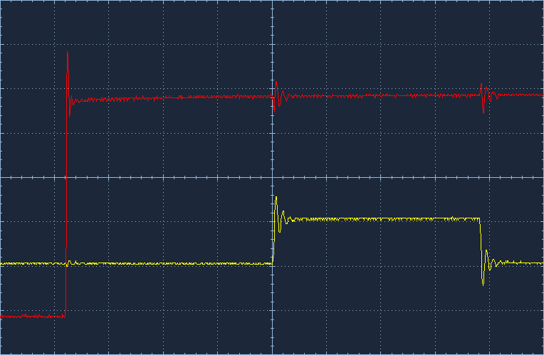
CapnBry posted:From the screenshots you posted it looks like when signal A changes state there is ringing on signal B and vice-versa. That makes it sound like you are switching large currents, and since you seem to be doing a reasonable job of trying to decouple stuff close to the chips the next place to look is at the load you are switching into. What is the input impedance of your probes? If they are terminated with 50 Ohms you would be drawing so much current out of each output that your decoupling caps can't keep up. A simple test would be to unclip your oscilloscope probe, clip it onto one side of a 10k resistor and plug the other end into the signal you want to look at. If the cross-coupling effect goes away the probe impedance is too low. Some scopes have a high/low input impedance setting that you can switch to fix the problem in a more permanent way.
|
|
#
¿
Jan 25, 2011 03:58
|
|
|
I have a pair of identical phototransistors that are configured as shown below with Re=10kOhm. When light hits the phototransistor current starts to flow and the output voltage goes up. I measure the output voltage from each channel with an A/D card inside my computer. So far so good, the signals are clean and about 1V peak-to-peak which the A/D card can handle at 16 bit resolution. Things start to get strange when I point both phototransistors at the same light source and modulate the light with a 1kHz sinusoid around a DC offset. The two detectors output a sindusoidal signal on a DC offset, tracking the input signal just like they should. Since the two detectors are looking at the same input I would expect the sinusoidal component from each channel to have zero phase angle relative to each other. Instead I get this:  There is a small amount of phase noise (~0.02 deg) sitting on a much larger envelope drift that varies slowly over about a degree. The small noise is due to a combination of digitization effects and numerical error in the algorithm I use to extract the phase angle. The big, slowly varying envelope function is a total mystery to me and is causing problems since this experiment needs to measure to +/- 0.1 degree accuracy. If I take the phototransistor circuits out of the system and just feed the A/D cards a sinusoid + DC offset directly from a function generator the 1 degree envelope goes away. Any ideas as to what could be causing this slow phase shift between the two phototransistors? I've been stuck on this for a week and it's driving me nuts. PDP-1 fucked around with this message at 00:15 on Feb 8, 2011 |
|
#
¿
Feb 8, 2011 00:09
|
|
|
Thanks for the comments. I think (hope) that the phototransistors don't need to be 'accurate' in the sense of having the same responsivity to the input signal. My rationale for this is that I'm only interested in the phase angle of the sinusoidal component, which I get by calculating phase=atan[Im/Re] where Im and Re are the imaginary and real parts of the sinusoid relative to some reference cosine wave. I'm assuming that Im and Re will scale with the amplitude of the signal equally so that the ratio Im/Re will be independent of amplitude and therefore independent of the phototransistor gain or light coupling.* I did consider heating effects too and tried to eliminate that variable by the super-scientific method of putting my fingers on the case of one of the phototransistors and watching to see if the additional heat affected the phase angle. No luck. Didn't think to try messing with the resistors. Also, everything is contained within a box to block out outside light sources. I think that should have the add-on effect of acting as a thermal insulator, at least once everything's been running a while and is warmed up. * semi-edit: Just before hitting the post button a thought occurred - what if the light->output voltage transfer function isn't perfectly linear? Could that cause errors in the measured phase angle since the analysis is basically taking a Fourier transform at only one frequency and Fourier transforms assume linearity? real edit: I just tried simulating a non-linear detector response. The system is still stable even when the light in -> voltage out curve is a pure cubic function. gently caress. PDP-1 fucked around with this message at 01:25 on Feb 8, 2011 |
|
#
¿
Feb 8, 2011 01:04
|
|
|
taqueso posted:What model are your phototransistors? I'd just been assuming a linear relationship between the light in and the current out of the phototransistor. Multiply that current by the emitter resistance value and get the voltage. It's obviously a massive over-simplification but the real output signal seemed to follow the input signal pretty cleanly so I didn't mess with making a more detailed model. Also, the system is only operated at one frequency (1kHz) and all the parts are rated for 10MHz or above so I assumed that any internal junction capacitances, etc. would have a small effect and at most produce a stable offset phase shift at 1kHz. The drifting phase error is really odd given the stable input signal frequency. Is there some other model that would be better?
|
|
#
¿
Feb 8, 2011 01:53
|
|
|
Ah, gotcha. Here it is - Osram SFH 303 FA e: The voltage source is 5V, coming from the A/D card which in turn comes off the computer power supply. There is a lead for the base connection, right now I'm leaving it unconnected. The input light wavelength is 808nm. PDP-1 fucked around with this message at 02:07 on Feb 8, 2011 |
|
#
¿
Feb 8, 2011 02:04
|
|
|
Any idea how you would go about biasing the base connection? In the handful of times I've used phototransistors in the past they just had two leads for the emitter/collector and the base 'current' was generated purely by the input light signal so I'm not really sure what to do when I have an explicit base lead. e: After looking into it a bit more it seems that the base lead is used to either enable/disable the phototransistor via an external control, or to bias the transistor into a conducting state to improve linearity on the output signal. You raise a good point in terms of the rise/fall times - when I linked the pdf earlier I looked over it again and was left wondering why I had thought it had a >10MHz bandwidth like the other components in the system. Maybe I misread microseconds as nanoseconds, who knows. Regardless, it seems like if the circuit is driven by a stable 1kHz sinusoid any junction capacitances should just produce a constant phase offset instead of something that wanders around seemingly at random. Kids at home - don't make phase sensitive measurements. Ever. They seem like a good idea at the time but are a bitch to get working right. PDP-1 fucked around with this message at 16:11 on Feb 8, 2011 |
|
#
¿
Feb 8, 2011 06:50
|
|
|
Thanks again for the comments.SnoPuppy posted:I'd still try biasing the base to see if that helps. You're trying to measure less than 1 deg of phase angle, so you want as good a system as possible. I'm not opposed to biasing the base, I just don't really know how it should be biased. I could set up a voltage divider or tie the base off to +V through some resistor but I'd have no idea what values to pick to ensure a particular outcome. SnoPuppy posted:Are you sure you're sampling the phototransistors at the same time? I ask because some cheaper acquisition boards will use a single converter and step through each input channel one at a time. It's also possible that the board triggers each channel independently through software, which would definitely add trigger jitter. I am using a pair of National Instruments 6250 boards, each taking one of the phase input signals and nothing else. They are tied together inside the computer by an add-on ribbon cable that is supposed to lock their clock and trigger signals together so that one of the boards controls all timing. I could be wrong, but I think the timing of the trigger signals is OK because if I feed both channels with the output of a function generator the resulting phase measurement is stable and shows zero phase +/- 0.02 degrees. SnoPuppy posted:Last, how are you measuring the phase offset between the two transistors? That could also be a source of error. Ugly MathCAD screenshot below:  I repeat this process for both signals and then find the phase of signal A relative to signal B by just subtracting φA-φB. Since this processing is done in software I can feed the algorithm a set of made-up data where I know the phase angle and then compare that to the output value. It seems to work pretty well, with about 0.010 degrees of residual noise which I assume is due to numerical error in the integrations. ------------- I only had a little bit of time to play with the system today, but I did make one interesting observation. First I started off by driving both signal inputs with a function generator that has a 50 Ohm output impedance. No phase shift. Next, just on a lark I stuck a 10kOhm resistor on one of the inputs but not the other. I saw about a 1 degree phase measured phase shift. This makes me think that the input to the A/D card must have more capacitance than I had assumed, and that with the phototransistor/resistor combo connected the A/D line is charging up through the phototransistor and decharging through the emitter resistor. If the two phototransistors have slightly different amounts of light coupled into them due to being in different locations the effective base bias of one might be higher/lower than the other, and the 'output impedance' of the two phototransistors may not be the same. My mechanical setup is flimsy as hell so if a truck drives by outside it may vibrate a bit, change the light coupling of the phototransistors, and thereby change the effective time constants of each channel. Different time constants gives different phase readings at least until the next truck drives by. I don't know. I'm going to sleep on this idea and hopefully tomorrow get some more time in on the system to check it out.
|
|
#
¿
Feb 9, 2011 03:58
|
|
|
Wow, that is a really good idea. I'll try it out tomorrow. Thanks!
|
|
#
¿
Feb 9, 2011 04:09
|
|
|
sixide posted:Somewhat OT but I had no idea those NI boards were so ridiculously priced. I recall scanning 32 channels of 10MHz signals (which NI products are far too slow for) in realtime for less than the price of their low-end 250 kS/s boards. I don't really disagree that they cost a lot for what they do. There are, however, a couple of factors that justify paying a bit extra: 1) These cards have 16 bit resolution. You can get cheaper, faster cards if you don't need that kind of detail in your signal but accuracy drops off pretty quickly as sampling rate increases. For example, you can get an oscilloscope or A/D card with a few hundred MHz bandwidth and a much faster per channel sampling rate for $1000 USD if you don't mind being limited to 8 bits on the A/D conversion. For (a lot) more money you can push it out to 10 bits direct sampling, or an effective 11 or 12 bits if you can average the signal over multiple cycles. In our case we estimated that we needed 14 bit resolution at 1 MS/s so a 16 bit card was the best available choice. 2) Say what you will about NI (I've had serious issues with some of their hardware in the past), but for the most part you just jam their equipment into your computer and *BAM* it shows up in LabVIEW ready to use. On the odd occasion when it doesn't work right out of the box their support is really good - I've posted issues on the NI discussion boards that get a response from a knowledgeable engineer in under an hour. That kind of ease of use + support is really important when you're working on some new measurement system - in early development we're much more focused on "oh God, there is phase jitter in the detectors" kind of issues and don't want to be distracted with configuring COM drivers for the hardware on top of that. Instead there's more of an attitude of "rough it out in LabVIEW, get it to work, and then go back and re-code the control system in a language that doesn't look like a clown barfed on your monitor". The NI cards work well with both LabVIEW and C#/.NET which supports both development phases well. So, card capabilities plus ease of use are worth a bit of cash up front if it will pay off in terms of getting the thing up and running quick. Also work pays for the hardware, not me, and I think they tolerate an extra $1k better than I would for a home hobby project. That said, I loving hate programming in LabVIEW and am getting to the point of just wanting to skip to C# so if there are better, cheaper options out there that support .NET lemme know. ")
|
|
#
¿
Feb 9, 2011 07:49
|
|
|
ANIME AKBAR posted:If you want to negate the effects of junction capacitance and biasing nonlinearities, you should use a transimpedance amplifier: I tried this out today, it did need an extra bypass cap in parallel with the feedback resistor to compensate for the phototransitor's junction capacitance. Without the bypass cap the op amp would self-oscillate wildly. With the extra cap in place the signal was nice and clean. Unfortunately, just as I was getting set up to do the phase stability test I plugged grounded wire A into +5V line B and popped a fuse in my power supply. I picked up a new fuse after work, will try the phase test tomorrow. e: One other thought I had was just to tap the phototransistor emitter voltage with a unity gain buffer op amp. The high impedance of the op amp should keep it from affecting the phototransistor's behavior while the low output impedance could drive the A/D input capacitance quickly. On the to do list. SnoPuppy posted:Have you tried feeding your algorithm data that is slightly off in frequency? Like 1.001 KHz? Or data that starts with an initial random phase offset (i.e. they might be be at 0/10 deg or 35/45 deg)? That's a good point about the two system timeclocks. I'm not using hardware triggering so the function generator and A/D boards might have some relative drift. With the technique I described, the initial phase offset doesn't matter as long as you sample over an integer number of wave cycles. Since I know the sampling rate and the modulation frequency I can tell the A/D card to collect N samples and have it be spot on +/- 1 reading. I think I looked at that phase measurement technique when we were spitballing ideas for the system design. It's kind of like what happens inside of a lock-in amplifier, except you're doing the math in software instead of in hardware. I think I remember calculating that you had to collect data over a certain number of cycles to ensure a particular accuracy since the filtered DC value oscillated for a while before settling into some stable reading. I should look at that again, my memory is a bit fuzzy. Still, I hadn't fully realized that that technique was frequency independent. That might be a useful trick for some applications of this system. TacoHavoc posted:Have you considered labwindows/CVI? It's C based and looks like it does .net integration. If your work springs for the development suite version of labview, you've got a license already. Labview is painful, but I'm stuck using it too. I've thought about switching over to labwindows, but I can't find the time to learn enough that my project deadlines won't be affected. Once you install the NI hardware drivers (including the .NET language support option which is often turned off by default) you can just link directly to the driver dll from C# or VB by including a reference to the dll in your project settings. I see what you are saying about LabWindows, and it does have .NET interfaces, but if you can just do the whole thing in a clean, modern .NET language and chuck the LabVIEW wackiness out the window I guess I'd prefer that to making some kind of frankencode out of a mix of two languages. PDP-1 fucked around with this message at 03:52 on Feb 10, 2011 |
|
#
¿
Feb 10, 2011 03:46
|
|
|
standardtoaster posted:I'm fairly new to this and something is still bugging me about current and diagrams. You are correct that the traditional sign convention shows current flowing from positive to negative voltage while the physical electrons are actually flowing from negative to positive. It's a historical fluke, people began playing with electricity and had a notion that something was flowing long before they understood what electrons are. They just picked a sign convention at random, and from the viewpoint of a physical electron they picked the wrong one. The good news is that for normal circuit analysis the sign convention doesn't matter. If you pick one convention and stick with it consistently you will get the same answers as if you had picked the other convention. Only your interpretation of the current will change - you would describe a current as "1mA flowing from A to B" or as "-1mA flowing from B to A" depending on which sign convention you picked. Mathematically it's the same current either way. 99% of the world uses the postive-to-negative current flow definition, so just go along with it to avoid confusing yourself and others. The other 1% are semiconductor engineers who really need to know where the physical electrons are going from and to, but if you don't work at Intel it's not a problem. PDP-1 fucked around with this message at 16:57 on Feb 11, 2011 |
|
#
¿
Feb 11, 2011 16:53
|
|
|
Tres Burritos posted:So I need to run as many Infrared LEDs as possible off of a usb to serial port adapter. Can anyone recommend a simple circuit and some LEDs? Which USB to serial port adapter are you using? Some adapters do an internal DC/DC voltage conversion that transforms the +5V of the USB line into the +/-12V signals normally used in RS-232. The USB port may be able to supply several hundred milliamps at 5V but after the voltage conversion you might only have 1-2 milliamps available on the serial port pins. For applications where you only want to connect two things for data communication the low current is fine since you would only be driving a few input pins on the RS-232 listening side, but for what you want to do 1-2 mA is not really enough to light up a bunch of LEDs. What are you plugging the cable into? It might have its own power supply that you could run the LEDs off of or you could run a second, unconverted USB line alongside the communication line to act as a power source.
|
|
#
¿
Feb 12, 2011 17:45
|
|
|
Ah, OK that does help. I thought you were talking about the cables that plug into a USB port and provide an RS-232 connection on the other end. Those have charge pumps inside to get the +/-12V RS-232 signals and the charge pumps kill your available output current. It looks like the guy you linked to is using a USB-Serial bridge chip without any charge pumps so the whole system runs off the 5V USB power supply. That means you can power the LEDs directly off of the USB line which is good. Skimming through the info he posted, it looks like he's doing something like this:  The USB connector is on the left and sends data to the bridge chip. The data gets converted to serial and sent out the transmit pin Tx. When Tx goes high it turns on the transistor and lets current flow through the LED. When Tx is low the transistor shuts off and the LED shuts off too. There should be some filter caps on the 5V line since the LED will draw a lot of current when switched on, and make sure that your Tx pin can source/sink enough current to run the transistor. Does that make sense based on your understanding of the helicopter control? Is there any data coming back from the helicopter?
|
|
#
¿
Feb 12, 2011 22:31
|
|
|
The best bet would be to ask the guy if he'd share a parts list or schematic with you. He seemed to be pretty open with his info on that forum. If that doesn't work you could just get an infrared LED from Radio Shack. Assuming that it had a 1.5V forward voltage drop and drew 100mA, then for a 5V supply with 0.7V across the transistor when its on you'd need R2 = (5V - 1.5V - 0.7V) / 100mA = 28 Ohms The pdf spec sheet for that chip you posted was pretty vague, they just list the Tx pin as some kind of 'TTL compatible' output so you don't want to draw more than 0.4 mA or so when it's on. That suggests that you'd need a transistor with a beta of (100mA / 0.4mA) = 250 and R1 = 10.7k Ohms. You might also think about using a Darlington pair driver in place of the transistor so you could just connect the TTL signal directly into the input and drive multiple LEDs at once. PDP-1 fucked around with this message at 01:27 on Feb 13, 2011 |
|
#
¿
Feb 13, 2011 01:15
|
|
|
taqueso posted:I've been looking at the LPC1114 version of the LPCXpresso boards: http://ics.nxp.com/support/lpcxpresso/pdf/lpc1114.schematic.pdf The bottom of the first page of the pdf you linked has the note "UL = UnLoaded = normally not mounted component", so I'd guess there are just some holes on the PCB where you can solder in the extra components if you need some extra functionality, or maybe access to some debugging/prototyping abilities.
|
|
#
¿
Feb 15, 2011 21:34
|
|
|
Rocko Bonaparte posted:PID stuff If you are using a computer algorithm you found online check to see if it clamps the I value. If the I value is getting clamped the Ziegler-Nichols method might not work since it expects a fully linear system and the clamping makes things non-linear. Unclamp the I value or set the range to something huge and try it again. You can also manually tune your parameters. Set the PID parameters to zero, then start at some low-ish P value and see if the system stabilizes at some steady (but wrong) temperature. Gradually increase the P value until the temperature begins to oscillate around the setpoint, then back it off again so you have about 90% of the largest P value that produces a steady result. Then bump up the I value until it settles into an acceptable error range. Like sixide said, most real-world systems don't need full PID control - normally PI is enough. Adding the derivative parameter is only really needed if you have a system with nearly zero damping/friction/heat-loss.
|
|
#
¿
Feb 25, 2011 04:14
|
|
|
The comments in the product page suggest that the hookup is black->ground, white->+V, and red is the signal output which should be about V/2 and change a little when pressure is applied. But yeah, that's really lovely documentation on SparkFun's part.
|
|
#
¿
Mar 11, 2011 03:23
|
|
|
Rescue Toaster posted:The PCB's are fantastic, I had them made by seeedstudio, though ITead supposedly resells the same exact service for even cheaper. $40 for 10x 10cm by 10cm boards, soldermask & silkscreen both sides. What are you using to do your pcb layout? I've been getting my boards from ExpressPCB mostly just because they give you some decent CAD software for free. Getting the boards masked/silkscreened/delivered from them was ~$80ish for three boards that are about 2.5" x 3.5". If there is some free/super-cheap way to make the Gerber files that ITead wants they seem to offer a much better deal.
|
|
#
¿
Apr 5, 2011 13:41
|
|
|
I'm totally, positively, 80% sure that a 5-pin DIN cable is a MIDI cable. I had to buy a 5-pinner a few months back for some equipment we use at our lab the Radio Shack version that was billed as being a MIDI cable worked fine. As far as I know DIN cables are pretty regular and don't suffer from the kind of 'non-standard standard' variations as, say, RS-232 so a 5-pin M/F cable should be OK.
|
|
#
¿
Apr 7, 2011 04:54
|
|
|
Kloaked00 posted:Anyone have experience hooking up a stop light before? How would I go about connecting this to a standard 120V wall connection? What does the COM stand for? COM is most likely short for 'common', meaning that all three lights share that connection. To hook it up I'd take a power cable, connect the ground wire to the case of the thing (probably via the bolt ends shown in your last picture), then white to the common terminal and the black/hot line to whichever one of the three lights you want to have on. Bad Munki brings up a good point too - try putting 25W bulbs or similar in there so it won't be obnoxiously bright to have hanging around the livingroom. Hillridge posted:Out of curiosity, how many of you are members of hackerspaces? DIY electronics are a big part of most of those places. I live in Stupidtown, USA and there aren't enough people around here interested to support anything like that but if you do make a thread please post a link here - I'd enjoy living vicariously through you guys until I can move out of this shithole.
|
|
#
¿
May 14, 2011 18:08
|
|
|
I'm looking for a connector that an equipment manual describes as being a "mixed-pin DB15" plug that has two oversized pins for drive current and a few smaller pins like this: actual picture:  Googling for DB-* returns so much stuff that finding what you really need is drat near impossible. Does anyone know what that kind of plug might be called, or know any company that manufactures this kind of thing?
|
|
#
¿
Jun 22, 2011 13:42
|
|
|
Yep, those links look like exactly the part I needed. Thanks!
|
|
#
¿
Jun 22, 2011 17:59
|
|
|
Bad Munki posted:Random: I'm no expert on laser pointers in particular, but I worked in the laser diode industry for several years and can tell you that there's no inherent problem with running a laser diode continuously so long as you can remove the heat. We designed our telecom-grade chips to run continuously with 100 year MTBF at 5-10W per emitter output beam power. My guess is that the laser pointer guys are worried about heat dissipation for two reasons: (1) They are most likely using a vertical-cavity surface emitting laser (VCSEL, pronounced vix-el) which is a laser chip designed so that the beam exits out the top of the device. The advantages of VCSELS are that it's easy to make a nice circular beam to collimate for the output and they can be tested in-wafer which is great because you can knock out the bad units before packaging and packaging is the main expense in any laser diode. The downside of VCSELS is that they are low power, low efficiency (produce a lot of heat), and don't dissipate heat particularly well because all the electronic action happens on the top of the chip and any heat generated needs to travel through the whole thickness of the wafer substrate to get to the heatsink. (2) The other problem they likely have is caused by the laser output needing to be in the visible wavelength. Visible photons are higher energy than IR photons, and the high energy photons are generated by high energy electron-hole pairs. To constrain and control a high energy carrier you need a semiconductor material that has a large bandgap. At IR energies there are several families of semiconductors that can do the job nicely, but at visible energies the material pallet gets pretty sparse. Carrier confinement (and therefore device efficiency) starts to drop dramatically due to not being to pick an ideal material set. Modulation shouldn't be too big an issue, many laser diodes are modulated and if you're worried about it the main stress happens at the semiconductor-heatsink interface due to the different thermal expansion coefficients of the two materials. I recently built a system that sinusoidally modulates a ~1W diode at several kilohertz and it's been running for months with no problem. Hell conditions for laser diodes is modulating with a square wave at a ~1 second timescale since that puts the most stress on the semiconducor/heatsink junction. tl;dr version: Visible laser diodes are inherently kind of inefficient and make a lot of heat, and if they are VCSEL type lasers they don't dissipate heat very well. For a cheapy laser pointer type device this means that you don't want to run it overly long, but if you could sink the heat better you could run it all day. PDP-1 fucked around with this message at 02:54 on Jul 9, 2011 |
|
#
¿
Jul 9, 2011 02:51
|
|
|
Corla Plankun posted:Is there a "rule of thumb" for pricing contractual work? I just placed my first bid ever and I'm curious how reasonable/outrageous it was. It was for a pretty simple microcontroller-based prototype for one of my coworker's pet projects. Assuming you're out of school and have held a full-time engineering job before, start by figuring out what your employer paid to have you around and convert it to an equivalent per-hour rate. I don't mean your take home salary here, but what your employer paid - including insurance, vacation, retirement, etc. That's the amount that someone was willing to shell out to keep you around. Then for consulting/contracting work you multiply that rate by 3x for shorter term projects that you have really strong expertise in, or 2x for long term (several month) projects or for things that you can do better than the person who wants to hire you but aren't truly an A-list expert in. You can shade the multiplier between those values depending on a lot of other factors, but that's the general range. The result might surprise you. For a reasonably experienced engineer $100-$200 per hour is not uncommon. Just keep in mind that you are running a business here and (1) You have to cover all your own insurance, equipment costs, etc., (2) You are working on 'plumber time' in the sense that you make a lot while you work but then can have long stretches of downtime where you still need to pay the bills, and (3) You are insulating the person hiring you from the risks of taking on a full-time employee that they might not need for the long run. Like some other professions that could be named, people don't pay consultants to work, they pay us to go away after the job is done.
|
|
#
¿
Jul 15, 2011 14:37
|
|
|
Krenzo posted:So I was messing around with making boards using the photo developer method. I made an owen splitter which splits a signal into two and has 20 dB of isolation between the two output ports. That worked perfectly fine. However, I then tried to make an amplifier, and it's not working very well. Without being able to see your circuit, my guess is that you're capacitively loading your amplifier feedback input with your ground plane setup. That extra capacitance slows down the feedback signal so the amplifier can't keep up with changes in its own output, causing the output signal to swing around wildly. By sticking your finger on the board you're introducing just enough bypass capacitance to stabilize the oscillator again. In addition to what ANIME AKBAR said regarding vias, take a look at the positioning of C3 and C4 on the original board - they are tied to a section of ground plane that is not connected directly to the transistor. On your board they are connected to the same ground plane segment as the transistor and if that plane is high-ish impedance they could be coupling signal into the amplifier, or capacitavely loading down the inputs.
|
|
#
¿
Jul 22, 2011 14:03
|
|
|
Slanderer posted:I'm seriously considering building an LCR meter for hobbyists/hackers/whatever, and I'm wondering, what features would people have a use for? If you're going to have a USB port I'd suggest thinking about skipping the onboard keys/screen altogether and instead run the controls and display on a computer. It'd keep your parts count down and save you the trouble of writing a mini OS and graphics display system, plus maybe eliminate the power supply. On the software side split things into a .dll that would take simple human-readable commands to set up the sweep parameters and retrieve the data and a GUI program to display/curvefit/manipulate the data. People who just want a cheap LCR meter could use the GUI program, and hobbyists who want to integrate the thing into their project could talk to the control .dll directly.
|
|
#
¿
Jul 28, 2011 02:03
|
|
|
JimbobDobalina posted:Where do you guys get PCB's made these days? I have a multi-layer design with loads of SMT and I've only ever etched my own 2 layer thru hole stuff before. I've used Express PCB for prototype stuff before and was happy with what I got for the money. They have a free software package that you can download to do the layout and they go up to four layers with optional solder masks and silkscreen markings. You mail them the output file from the layout program and they send you the boards in a couple of days. It can be really cheap ($51 USD for three copies) if you can conform to one of their standard sizes, somewhat more if you need a larger board that is routed to a particular shape. To be clear, I only used them on one project for some very basic signal conditioning modules. We took the extra solder masks and silkscreen options and got three boards for ~$75 USD, and then assembled the components ourselves. Their software package isn't amazing but it isn't terrible either and only took like 15-20 mins to learn.
|
|
#
¿
Mar 8, 2012 05:26
|
|
|
Since it's o-scope chat day, can anyone recommend a scope with ~1GS/s, 8-bit or better for one channel for measuring a 0-5V analog pulse? I'd need to be able to interface it with a PC somehow, just enough to collect the trace data after collecting one shot. Price matters too, this particular company hates spending money on silly engineering tools. I would absolutely love it if I could find a PCIe card scope with these specs but nothing I've seen in my (admittedly brief) search even comes close. Next best option would be a standalone used unit with a GPIB/USB interface.
|
|
#
¿
Mar 22, 2012 14:52
|
|
|
sixide posted:If price is your primary concern, get one of the budget Rigol scopes. They meet all your requirements. I'm assuming you don't need a huge bandwidth if you're only looking for 1 GS/s. Thanks, I'll check them out. I haven't used Rigol stuff before, does anyone have experience with them who can comment on the build quality, software interface, etc? sixide posted:I'd love to make test equipment--as a career. The amount of engineering required to do a halfway decent job is a bit much for a hobby, I think. I once thought about trying to come up with a line of hobby-level stuff myself. My plan was to make a generic powered backplane with USB connection, then have modules that would clip into it to provide functions like voltmeters, mini-oscilloscopes, low-wattage power supplies, etc. Mix-n-match the modules to build the lab kit you wanted, expand it later as needed. Control and readout would all be done on a PC connected to the USB port. Physically it'd be somewhat like the National Instruments RIO system, but without the controller unit or calibration traceability to keep things cheap. 
|
|
#
¿
Mar 23, 2012 19:47
|
|
|
What software do the cool kids use these days for analog simulation and schematic layout? I've been asked to take a look at a system that's built out of a pile of discrete BJTs and MOSFETs and to build an interface between it and another system, but hoo boy has it been a while since I've worked with that kind of stuff. Ideally I'd like to simulate the existing circuit to get to understand it better, then add on any interface parts that are needed and produce a decent looking schematic drawing. Budget for this project is somewhere between zero and a couple of hundred dollars max. Any suggestions? Is PSPICE still the standard go-to?
|
|
#
¿
Aug 1, 2012 20:01
|
|
|
DahtBard posted:I'm not sure if you access to more popular/paid-for software, but as far as free I use LTspice SnoPuppy posted:LTSpice from Linear Tech. Just checked this out and it looks like it'll do the job. Thanks!
|
|
#
¿
Aug 2, 2012 00:04
|
|
|
Forer posted:I haven't worked on the counter from earlier but the issue was a float, I'm assuming the float issue is "oh hey no voltage SHOULD be transfering but it's in a state now where we can't adequately predict what it will do" How do I solve that issue so a pin is either 5v or 0v and not inbetween I'm not 100% sure I understand what you're doing without a schematic, but given your earlier statement that the circuit starts doing things when you put your finger next to it I'd guess that you have a high impedance node somewhere. The idea is that you have some node that has only high impedance outputs (say a CMOS style gate imput) that is driven by a source that goes into a high impedance state when shut off, leaving the node effectively 'floating' such that its actual voltage is unpredictable and totally dependent on random stray or capacitavely coupled charges. The solution would be to add some high-ish value resistor tying the node to the voltage you want it to be at when the input is in the 'off' state, like +5V or GND. Choose the value to be large enough that it doesn't load your input source, say something in the 10k-100k range.
|
|
#
¿
Aug 12, 2012 15:36
|
|
|
Can anyone remind me of the name for the digital encoding system where adjacent states differ by exactly one bit? For example, a two-bit system would have the sequence 00 01 11 10 It's used for motor control systems so that you can tell where you are and which direction the motor is turning by observing which bit was the last to change.
|
|
#
¿
Aug 16, 2012 20:23
|
|
|

|
| # ¿ May 5, 2024 17:46 |
|
|
That's the one! Thanks a ton, it's been on the tip of my tongue all morning but I just couldn't quite remember the term. Googling for variations of 'binary code' isn't exactly helpful in this case either. And yeah, I think quadrature also applies for simple two-bit cases too. I should have specified that I was looking for the more general Gray code case.
|
|
#
¿
Aug 16, 2012 21:39
|
|