


|
DC is far, far easier to work with. At my school, we were encouraged to: A) Book a lab that had variable DC power supplies B) Use 9 volt batteries, possibly alongside a 5 volt regulator if we were working with digital stuff, or C) Use the power supplies that we designed and manufactured as a term project. Option A probably isn't available to you, and option C took a couple months to build and $80 in parts. Option B just sucks. What a classmate of mine started doing out of frustration at our limited options, was just using a cellphone charger. Buy a 5v cellphone charger at a mall or something, shouldn't cost more than $10. Then, just split the output wire. Put them in banana jack output plugs or something from radio shack.
|
 #
¿
May 18, 2008 00:51
#
¿
May 18, 2008 00:51
|
|


|

|
| # ¿ May 5, 2024 11:51 |
|
|
Delta-Wye posted:I'm thinking about building a metronome, and shopping for some components. Has anybody had any experience with little LCD character modules? (http://www.lumex.com/product.aspx?id=463) The datasheets are wonderfully vague. I was hoping to drive the characers with digital i/o ports like a 7 segment display (but using less power, hence LCD) but it claims it wants 5V AC. Does this have to be true AC? would rapidly switching DC be alright? does this mean 0-5V or -5-5V? So many unanswered questions, and I really don't feel like ordering one to blow up experimenting with/decide it won't meet my requirements. It needs -5 to 5 for it not to die in a couple weeks. The way that I did it in class was to use an XOR gate for each of the LCD's pins. Something like this:  You'll need a gate for each of the 8 LCD inputs (A-G, and DP if you want it), so two XOR chips.
|
|
#
¿
May 30, 2008 11:24
|
|
|
Bush is a QT posted:All of you guys are really reminding me about my Electronic Devices class. It's the class where you learn a lot a transistors and stuff. I just had one problem with it. You're supposed to say that you couldn't resist
|
|
#
¿
Jun 15, 2008 07:26
|
|
|
Metajo Cum Dumpster posted:1/2 1/4 1/8 watt carbon filter resistors? That number corresponds to the maximum power that you can put through the resistor before it'll burn out. Power = Voltage drop over the resistor * Current These formulas won't necessarily mean anything until you really get into building a circuit. And for the vast majority of your starter projects, 1/8W resistors should be fine. ante fucked around with this message at 22:02 on Jul 18, 2008 |
|
#
¿
Jul 18, 2008 21:46
|
|
|
What's the difference between unipolar and bipolar motors? I'm looking for a cheap reversible motor that can run off 9VDC, doesn't need to go more than 10RPM or so. What are my options?
|
|
#
¿
Aug 19, 2008 11:12
|
|
|
Ok, what are these called, and where can I get/make a custom one? Click here for the full 1024x768 image. Is it just another form of ribbon cable? I need to use one in a project I'm tinkering around with that I'll post up here when(if) I finish. ante fucked around with this message at 01:18 on Sep 9, 2008 |
|
#
¿
Sep 9, 2008 01:16
|
|
|
mtwieg posted:Okay I'm narrowing down the topics a bit. After thinking about it, AVR tutorials would be really involved, and people likely won't be interested in ASM, and I doubt I could do a much better job than some of the existing tutorials out there. And resonance oscillators would only make sense to people who already have a firm grounding in EE, so that's out. Definitely transistors. My transistor course this term is taught by a horrible teacher 
|
|
#
¿
Sep 12, 2008 04:44
|
|
|
SovietSpyGuy posted:What kind of decoders/encoders? It's probably not a good idea to stock up on dozens of chips if you don't know that you'll have a use for them, though. Some of them you'll never find a need for, and they'll just sit in your drawer, taking up space. There are thousands of chips that do almost anything you need if you have a specific use in mind. I've got a pretty complete collection of the basics, but I was working on a project a couple months ago that require as compact a PCB as I could get. I needed to count up to an eleven-bit number, and run some logic off that. What I didn't want to do was to use two 393 counter chips and a 555 because of the size requirements. After a bit of googling I found one chip that that does both of those. It's a timer/11-bit counter. The point is, find a good electronics store nearby that you can do runs to whenever you need something in particular.
|
|
#
¿
Nov 17, 2008 10:05
|
|
|

|
|
#
¿
Nov 27, 2008 02:29
|
|
|
Solaron posted:I'm looking for the smallest IC/speaker to make a beeping noise. I'd like to mess around with making something (similar to the keyfob on a car where you push a button and a receiver beeps). I don't know for sure how long the battery will last, but I think should be fine. Watch batteries can be either ~1.5v or 3v. Make sure you get the 3v variety. The buzzer also needs an AC input, so maybe look into a low power 555 timer, or a couple transistors in an oscillator circuit.
|
|
#
¿
Dec 11, 2008 01:25
|
|
|
Grand_High_Took posted:Any thoughts? Some apartment buzzing systems don't need a valid number on the landline, just the phone itself. Someone I know has a phone in his apartment with no plan or anything on it, its sole purpose is to buzz people in. I'd look into that, first. If you have to hack the hardware could you post a link to the datasheet of the chip you have to emulate?
|
|
#
¿
Dec 13, 2008 02:38
|
|
|
Get something that makes a noise, like a child's toy, short circuit stuff, see what happens!
|
|
#
¿
Dec 14, 2008 03:12
|
|
|
csammis posted:This gives me pause: http://arduino.cc/en/Reference/SoftwareSerial - it sounds like the API has some serious drawbacks. Would a different platform be a better way to go? That's a library designed to use more than two pins for serial communication. You'd wire up the Arduino according to this, connecting each Tx and Rx pin to each other. Because of that, you wouldn't have to use that library, so you'd have none of the associated drawbacks. Use this instead. Arduino will work fine for your project.
|
|
#
¿
Dec 26, 2008 06:19
|
|
|
No, looks good to me.
|
|
#
¿
Dec 27, 2008 10:57
|
|
|
There are plenty of hole in the wall electronics stores around if you know where to look. Just through asking around, I've found five in Vancouver, all good for different things. One has walls covered in switches like those mentioned above, one has dirt cheap resistors, one has all the CMOS chips I need, that kind of thing.
|
|
#
¿
Dec 28, 2008 00:55
|
|
|
Metajo Cum Dumpster posted:Where should I get started with microcontrollers once I get the very basics of electronics down? I've become a big fan of the Arduino board, which I found through the forums. Basically a $40 board that comes with a pre-flashed AVR that you can program using C. It's a very good stepping stone to programming AVRs that doesn't require any hardware other than a USB cable. (after you get comfortable with that, you can flash your own AVRs using a homemade cable made with three resistors, a piece of wire, and a sliced up parallel-serial adapter) edit: On the other hand, the only local AVR distributors sell them for about $10, while I've seen PICs for $3
|
|
#
¿
Jan 6, 2009 01:31
|
|
|
Metajo Cum Dumpster posted:Thanks guys. I still have a very limited knowledge of microcontrollers, so bare with me please. Arduino has its own C compiler. The board and the official site make it really really easy to get into. You download the software, install the driver(just double click it!), and plug in the board. That's it. Other AVR setups or PICs may have advantages or disadvantages, but you're certainly not locked into the Arduino once you start using it, it's just a great way to learn. One thing I'm planning on doing in the near future is getting a few PICs and learning assembly with them. I'm going to need to be able to accurately control how many clock cycles everything takes for a project coming up. If I jumped right into that, it'd be pretty tough, though. Even wiring everything up can be a hassle sometimes, and it'd all be on breadboards.
|
|
#
¿
Jan 6, 2009 05:39
|
|
|
Metajo Cum Dumpster posted:Decided I want to start with the Arduino as it's cheap, open, and want to practice my C. The Duemilanove is the basic one, just get that. The shields add functionality like bluetooth, internet(wtf), stuff like that.
|
|
#
¿
Jan 7, 2009 22:47
|
|
|
I'll go through the analogy I use. Keep in mind that voltage is not an absolute value. It is a potential from one point to another, point A with respect to point B. Picture a mountain. On that mountain, imagine a single point. That point has an elevation, but elevation is not absolute. It's measured in metres above sea level. That's the height of the point with respect to the height of the sea. So, 300 metres above sea level, 10 volts from the positive terminal to the negative terminal. Same thing. On that mountain, there is a stream going from one point to another. It travels from the higher altitude to the lower one (+ voltage to -), and the amount of water going along that stream is the current. Pressure, I guess. Assuming ideal conditions, the source of the stream can supply infinite pressure, so don't worry about that part. Because of this, the pressure of the river depends on how wide it is. The wider it is, the lower the resistance, the more water flows along it. By the same token, the steeper the slope is, the more water will flow through. If you look at the mountain dead on, it'll look something like this:  The equivalent circuit is something like this:  The parts of the river that are very wide are wire, no resistance, no voltage drop across them. The drop in altitude/voltage across each element depends the familiar Ohm's law, and all that. If you get a break in the river, no water is flowing, so the potential to flow is the same all along that stagnant water. An open circuit is the exact opposite of a short circuit. With no resistance, the river is infinitely wide, so an infinitely large amount of water is try to push through.
|
|
#
¿
Jan 10, 2009 02:50
|
|
|
Aluminum Record posted:Someone also once posted a little project of turning a computer power supply into a bench top hobby supply with a bunch of different outputs. Anyone remember it? I think it may have been posted separate of this thread, probably in the archives by now. Maybe a good reason for me to finally buy access. Can you remember a thread title, author, or even a thread icon? Shouldn't be particularly hard, though. They already have a couple different outputs.
|
|
#
¿
Mar 23, 2009 01:34
|
|
|
What about using a device-tracking directional antenna?
|
|
#
¿
Jul 9, 2009 09:31
|
|
|
Just attach a head to the pot that has a peg hits something on the chassis at 90'.
|
|
#
¿
Aug 5, 2009 16:03
|
|
|
You can use this example to do what you want: http://www.arduino.cc/playground/Main/DirectDriveLEDMatrix Use some latching chips to expand it past the normal pin capacity, and treat each colour like a separate grid, I guess. Does that make sense, or should I elaborate a little?
|
|
#
¿
Aug 6, 2009 11:26
|
|
|
Some of the literature for the XBee I've seen indicates that it can handle around 9.6kbps of throughput. That's enough to send voice. Many Ventrilo servers use less than that. It won't be very high quality, though.
|
|
#
¿
Aug 7, 2009 02:33
|
|
|
gently caress the FCC. Actually, that's a good idea. It's even legal if you just use walkie talkie(49MHz) or CB(27MHz) frequencies.
|
|
#
¿
Aug 7, 2009 03:17
|
|
|
Quartus can do it. Create a block/schematic file.
|
|
#
¿
Aug 11, 2009 04:17
|
|
|
You want software that can generate gate logic based on inputs/outputs that you specify? I know that there is stuff on the web that can give you an equation that's usually pretty similar to something you could come up with by hand. It's not very hard to draw that out with the proper symbology. A better solution is to do it yourself/learn how to do it yourself, though.
|
|
#
¿
Aug 11, 2009 04:59
|
|
|
Arduinos board have a 16MHz crystal in them when you buy them, and they're only rated to about 20MHz. There are way faster microcontrollers out there. Here's a handy guide, if you don't mind using PICs. If you use an external clock, you can go up to 120MHz. Atmel doesn't have a comprehensive list like that, unfortunately, but I think they're generally limited to 32MHz.
|
|
#
¿
Sep 15, 2009 04:11
|
|
|
Exitlights posted:Would a faster clock be enough to produce a faster serial connection? Or is there some limitation imposed on the computer's end for receiving serial data? Since I'm looking at using my laptop, I'd be using some sort of USB->RS232 thing. The original RS232 standard had an upper limit of around 20 kbps, but that little dongle you're using should go up to 1.2Mbps, according to a datasheet I found. (  ) )clredwolf posted:There are some ready-made solutions, but they tend to be expensive or bulky. How big is this RC boat? If you're using 802.11 with Arduino, you'll probably be using the XBee module, which is pretty slow, I hear.
|
|
#
¿
Sep 16, 2009 01:12
|
|
|
What do you have in mind? Get some concrete plans, first. Draw out a top-down view of the project you want to build. Include all of the doodads. When you're done that, you can post it here, and we'll point you in the right direction. Oh, and here's a suggestion: if you put an offset weight on the shaft of a little DC motor, it'll move the project box around.
|
|
#
¿
Sep 23, 2009 00:44
|
|
|
jovial_cynic posted:I'm picking up a datalogger (logomatic v2), which can take in 8 analog signals, and using it to pull data from various signals from my car. The only problem I'm having is with trying to figure out how to get RPMs pulled in.
|
|
#
¿
Oct 14, 2009 09:38
|
|
|
ACanofPepsi posted:It scares me to have the thing with batteries in, wired to my electronics while also plugged into the wall. Like I said, I'm new to batteries and wiring power in general. I'm sure my fears are unfounded. I'd also like to be able to just pop in a new battery and keep shooting, while leaving my dead battery in another charger against a wall somewhere. This method sounds a lot easier to me, too. Both in the execution and in function. quote:Is there an online beginners guide for this kind of thing? I'm having a hell of a time finding useful results with Google. If you're using a charger to connect the battery to the rig, just open it up and take a look inside. You won't need most of the circuitry, that's for rectifying the AC and stuff. Just figure out where the common and 12v connections are and wire those to your LCD. Get a multimeter, too.
|
|
#
¿
Oct 16, 2009 18:09
|
|
|
ozziegt posted:I want to build a peak hold module. This is the setup: What's your setup for transmitting the peak value, if you've gotten that far? I don't see any reason you'd go with #2. The sensor is always transmitting data, and your device is always sending the peak value, the switch would just toggle which one connects to the gauge.
|
|
#
¿
Nov 16, 2009 21:41
|
|
|
What microcontroller are you using? You'll need some sort of DAC, and many microcontrollers come with them. If yours doesn't, no biggy. External DACs are usually better anyway. Either way, you'll need one. You'll also need to figure out how the sensor works. It will either generate current or, more likely, have a variable resistance. Play around with it using a multimeter if you have one. It should act just like a potentiometer. One of the leads should be the pole, and the resistance between the other two leads will always be constant.
|
|
#
¿
Nov 16, 2009 22:09
|
|
|
ozziegt posted:e: nvm, I think I understand...I just need to output the same voltage that the sensor would output when given the proper input voltage. Right? ozziegt posted:My understanding is that the gauge is controller with a stepper motor. Does that change anything? Possibly. It's probably fine if it has controller circuitry, but double-check that the microcontroller isn't going to be directly driving the motor. That'll burn it pretty fast.
|
|
#
¿
Nov 16, 2009 22:30
|
|
|
Could you make four intersecting bars close in on the neck of the bottle, locking it in place? That should probably centre it well enough to drop a funnel into it. edit: or some sort of lasso, you could drive that with a single stepper ante fucked around with this message at 00:36 on Nov 17, 2009 |
|
#
¿
Nov 17, 2009 00:33
|
|
|
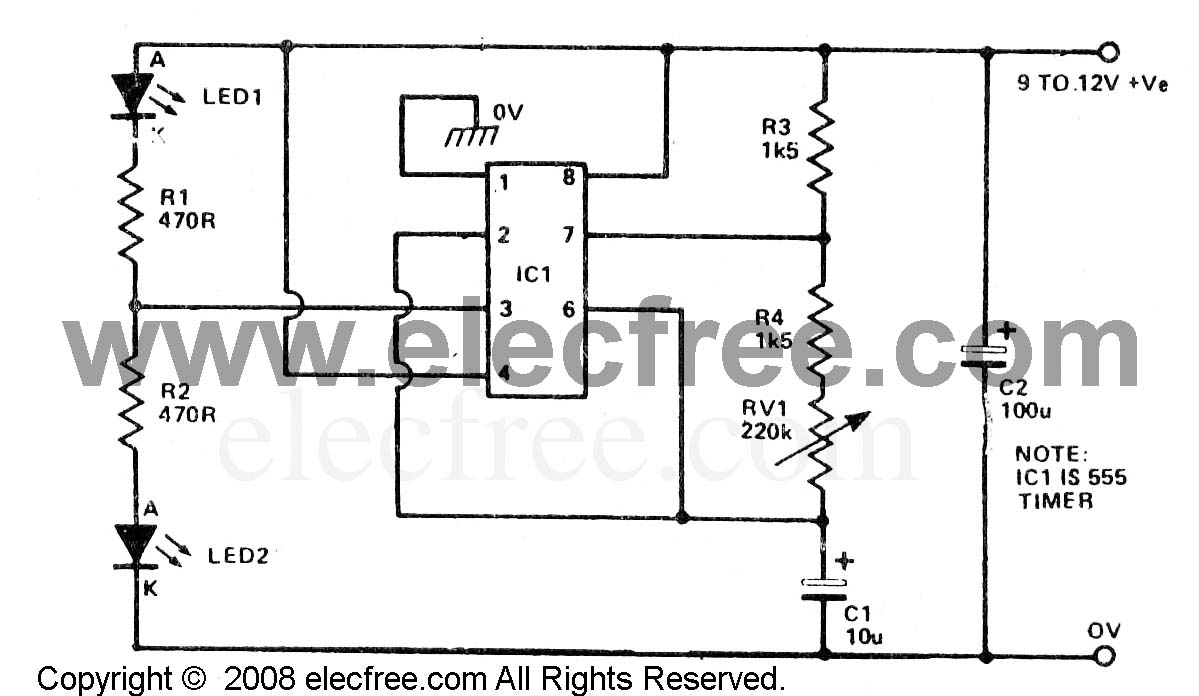
greg_graffin posted:Quick question for somebody just getting into building circuits. I'm trying to make a 555 circuit to flash a pair of LEDs, but I can't even get the LEDs to light up. I'd like to know if I built it correctly. Also, any breadboard layout tips? 1. Looks like pin 4 should be going to Vcc, not ground. 2. What's going on with the LED on the far left? Looks like it's getting shorted to ground. 3. Your resistor values are all different than the schematic. That might be intentional if you're playing around with different frequencies. 4. You are... Powering the circuit, right?
|
|
#
¿
Nov 19, 2009 07:35
|
|

|
Dassiell posted:Also I can't tell from here, make sure your LEDs are the right way, they are polarized. Anyway, I am looking for a basic cell jammer schematic, any idea where I can find one? Bottom's definitely in right, but that's true, can't tell for the top. Cell jammers are illegal in most places 
|
|
#
¿
Nov 21, 2009 00:31
|
|
|
nobody- posted:I'm interested in building a high voltage, low current power supply so I can make my own ozone generator like this guy did with a cold cathode driver: Frequency won't change the output voltage. The transformer and the input voltage are the limiters. Either get a different transformer or raise the DC voltage powering the 555. In both cases, make sure that you check the 555's datasheet. It has limits in both what kind of current it can drive, and what input voltage it can take. There are many different kinds of 555s with many different specs. macpod posted:I'm working on building a tiny lightweight gps tracker that charges and interfaces over usb. To power it I want to use lipo batteries. You're looking for a one-chip solution?
|
|
#
¿
Dec 10, 2009 05:33
|
|
|

|
| # ¿ May 5, 2024 11:51 |
|
|
No
|
|
#
¿
Dec 12, 2009 22:17
|
|