


|
Hillridge posted:I approve of this thread! Thanks for the info. I'm getting tired of buying new tips and irons every few months. I'm also interested in what other tools are needed for a good hobbyist setup. Heat gun and a big old pile of heatshrink tubing are definitely on my list of things to get. Should I look for anything in particular in a heat gun? Are temperature/CFM/BTUs/etc important or will whatever's in stock at the local industrial electronics store be fine? I'm also interested in getting a vacuum rework station. How cheaply can I find a good one, and what brands should I look for? Last question, when I started tinkering with things as a kid, my dad instilled a fear of flux in me, because ZOMG ACID. As a result, I've never used it, to this day. How bad is flux really? Will it eat my skin if I spill it on myself or just hurt a bit? What safety precautions should I take? For other people who don't have tools yet, here are some of the things I find indispensable: - Jeweler's screwdrivers . These are tiny little screwdrivers. Don't get the crap ones from Radio Shack, they suck and will fall apart or even be defective out of the box. I once got one where the tip hadn't been stamped or ground or whatever they do to form them, so it was just a rounded cone instead of a Phillips. - Needlenose pliers. Obvious, probably. - "Helping Hands." Those things with a weighted stand, a magnifying glass and two alligator clips on adjustable arms, for holding tiny stuff you're working on. They have a tendency to tip over if you even look at them funny, so fasten them to your workbench somehow. - A jar of soldering iron tinner. This is an incredible time and frustration saver compared to tinning by hand. Everyone should have one (that reminds me, I need more). Sometimes if stuff won't fir in the helping hands for whatever reason, I just tape things to the board or my workbench while I solder them. - 3-claw part retriever. A little round thingy with a plunger on one end and a springy metal claw on the other. You push the plunger and the claw opens up, let go and it springs back. Great for retrieving fiddly bits that you dropped into the case of whatever you're working on.
|
 #
¿
Jan 8, 2008 22:17
#
¿
Jan 8, 2008 22:17
|
|


|

|
| # ¿ May 1, 2024 09:18 |
|
|
Hillridge posted:A good thing to do to keep your iron tips fresh and shiny is to "tin" them before turning the iron off. Basically cover the whole tip with a big glob of solder and let it cool on there. When you need to use the iron again, just let it heat up and wipe off the solder on the sponge. quote:By heat gun I actually meant one of these guys: quote:
Well, I definitely need to upgrade something. Desoldering a single part can take me half an hour or more if it's stubborn and has a lot of leads. Thanks for the informative post! Mill Town fucked around with this message at 01:15 on Jan 10, 2008 |
|
#
¿
Jan 10, 2008 01:11
|
|


|
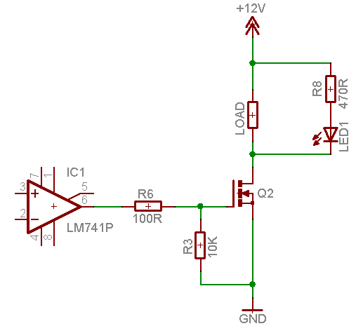
Vaporware posted:And here's the circuit from the chip manual I think your LED might be hooked up backwards. You have pin 7 shown as LED- and pin 16 as LED+ in your first photograph, but the schematic I quoted has it the other way around.
|
|
#
¿
Sep 25, 2008 18:22
|
|

|
Delivery McGee posted:If I do go the detonator route (with a few big batteries), I'm planning on wiring up a switch to pick between series and parallel on the batteries; is this possible? Absolutely. Here you go:  Someone else should probably check this to make sure I'm not shorting anything out by accident. It's late and I'm tired. Oh also, that's a single DPDT switch in there.
|
|
#
¿
Dec 27, 2008 09:32
|
|
|
mtwieg posted:Okay I set up a filer account and I uploaded the technical report of my SODAR project. Before I make the thread on it I wanted to make sure I've got the hosting set up right. So just let me know whether this link works or not (should go to a pdf of the report). Works fine.
|
|
#
¿
Dec 27, 2008 21:53
|
|
|
Delivery McGee posted:Like ante said, any decent-sized city should have some kind of hole in the wall, or at least an electrician's supply house. Depends where you are in Canada, though. Canada is loving huge. I can tell you where to find such things in Halifax, Montreal or Toronto. Are you anywhere near any of those places, BattleMaster?
|
|
#
¿
Dec 30, 2008 00:53
|
|
|
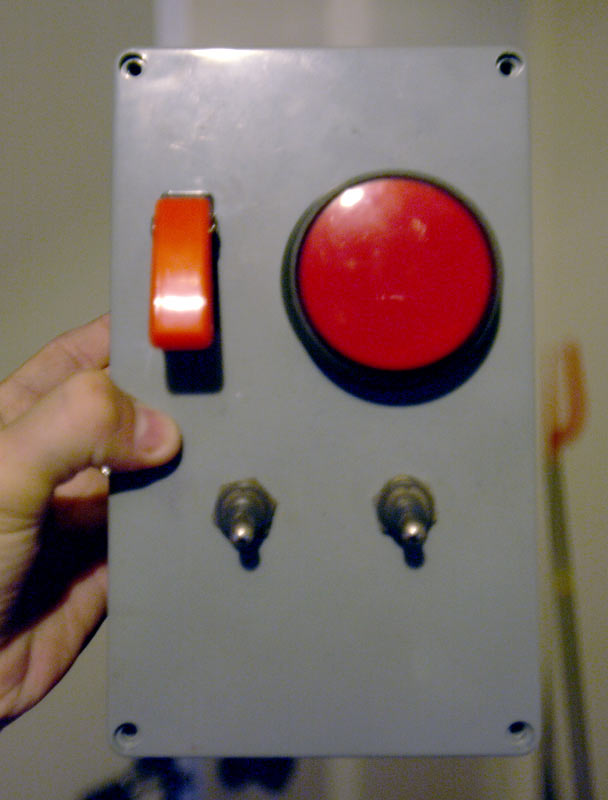
BattleMaster posted:Awesome, I thought it was going to be hopeless to find something like that because Delivery McGee said his was military surplus. All the "military surplus" stuff we have here is stolen, fake, or pre-Korean War. OK, what you want to do is head down to Active Surplus. I can't guarantee that they'll have the big red button, but they will have a nice assortment of similarly awesome things.
|
|
#
¿
Dec 30, 2008 08:48
|
|
|
Snaily posted:I'm looking at making a dimmable LED light fixture by making a variable duty cycle square wave with a 555, and I was going to use this circuit. Do you mean that the frequency changes as you adjust the pot (this is normal) or that the frequency changes on its own without adjusting the pot (this is not normal)?
|
|
#
¿
Jan 26, 2009 18:25
|
|
|
Snaily posted:Frequency changes as I adjust the pot. I was under the impression that this would not be the case (as stated below the diagram). Or in any case, I thought the frequency should be the same for 10% and 90% duty cycle if not in between. Normally with a 555, the frequency depends on both the resistors and capacitors, so changing any one changes the frequency. However, looking at that diagram again, it does look like they have designed it a bit differently, perhaps in a way that's supposed to avoid this. Maybe your simulation is wrong, I dunno.
|
|
#
¿
Jan 26, 2009 19:36
|
|
|
IfIWereARichMan posted:(crossposted from the quick question thread) Resistors are absolutely NOT the right way to limit current in an application like this. Even if they were affordable or practical, the excess power bot being consumed by the heating element would be dumped by the resistor, generating... wait for it... heat. You might as well just stick part of the heating element outside the gun. The resistive element is probably just controlled by a simple dimming-type circuit, with feedback from a thermistor to regulate the temperature. You could replace the controller with your own microcontroller, but that's kind of an involved project and probably would cost more than $20 overall. Edit: wait, I think I got this backwards. We want the controller to think it's 350 degrees when it's actually 200, or whatever, which means we need to lower the resistance. So you'd need to put a resistor in parallel with the thermistor. Start with a very high value resistor and work your way down until you get the temperature you want. If there isn't a thermistor, and it's a straight-up dimming circuit, you could probably remove all the electronic guts and just replace it with a light dimmer. Mill Town fucked around with this message at 22:53 on Jan 28, 2009 |
|
#
¿
Jan 28, 2009 22:49
|
|

|
IfIWereARichMan posted:I put a 600 watt rotary dimmer inline on the neutral lead from the power cord, allowing me to keep the control panel attached. And it worked without starting any fires! This was the major hurdle for this project, although unfortunately, the dimmer also slows down the fan, which has made it difficult to pin down the range of acceptable positions for the rotary knob. My advice would be to put the dimmer knob in the body of the heat gun, attached directly to the heating element. Then hook the power cord up to the element/dimmer combo in parallel with the fan. Get rid of the existing circuit board entirely. Edit: Although, since it's drawing 1500W max, you should get a bigger dimmer.
|
|
#
¿
Jan 29, 2009 06:02
|
|
|
ANIME AKBAR posted:Well you could build your own dimmer with a triac and some simple external circuitry. Can't say how expensive the triac would be though. The existing circuitry probably has a triac in it already so that's not a big deal.
|
|
#
¿
Feb 2, 2009 14:18
|
|
|
clredwolf posted:if you think about it, it's the same is 'voltage is across, current goes through'. Yeah, this. My brother works at an LED lighting shop and he's been calling me a lot recently with some "I've got these LEDs and I need to drop some extra voltage, where's it going?" type questions, and I've basically been repeating this to him. "Voltage is across things, current is through things."
|
|
#
¿
Feb 13, 2009 06:23
|
|
|
Plexiwatt posted:Quick question: I've got a circuit built on a breadboard that I want to make permanent--can I just blob some hot glue over the components and encase them? It's nothing too high-current. It seems like that should work, but 1) it's an expensive solution and you'll probably never get the breadboard back and 2) if something fails or comes loose it'll be a bitch to find and fix it. Just run out and buy a soldering iron and a perfboard. You can get ones with the same trace arrangement as the solderless breadboard so you can just transfer everything over to exactly the same spots. ozziegt posted:So I am messing around with microcontrollers and everything I have read said to buy BJT transistors. But the first post in this thread says MOSFETs are better. So just wondering why all the talk recommending BJTs...is it because BJTs cost about $.10 each while MOSFETs cost $2? Also, are they implemented the same way in a circuit? The other cool thing about MOSFETs is that they don't need a current-limiting resistor on their gate (the equivalent of a transistor's base). In a circuit with a lot of outputs, this can save you a lot of soldering time. The other uncool thing about them is that they're static sensitive so you have to be careful about handling them.
|
|
#
¿
Feb 15, 2009 01:47
|
|
|
Argh, some fucker in the shop lost the cap to the flux and then someone else left it near the drill press. Which someone else was using to drill aluminum. Guess what happens when you solder a circuit using conductive flux?   
|
|
#
¿
Feb 24, 2009 09:11
|
|
|
ANIME AKBAR posted:aaaaaaaaaah christ The best part was how when I took it off the bench and tested for shorts, I didn't find them. Then I'd put it back down (on a piece of paper to make sure I wasn't touching any scraps on the bench) and power it up, and it'd act fine for a few seconds until all the output transistors just turned on by themselves, and a few seconds later it would start smoking again. Or sometimes it would see a flash of light coming through the board and unplug it right away. It wasn't until I started thinking about why there were so many bits of crap in the flux that I figured out what was going on. In related questions, what's the best way to get flux off a board? 
|
|
#
¿
Feb 24, 2009 20:23
|
|
|
Cyril Sneer posted:Okay guys, a big one for ya. Wasn't sure if I should start this as another thread, but here goes. That looks like the LED sign that the guys at hacklab.to recently reverse-engineered. Informative blog post here: http://www.andrewkilpatrick.org/blog/?page_id=795 Also try their IRC channel at #hacklabto on Freenode if you have more questions. Edit: Did you get that at Active Surplus? Mill Town fucked around with this message at 01:11 on Mar 1, 2009 |
|
#
¿
Mar 1, 2009 01:08
|
|


|
Cyril Sneer posted:My god, thats EXACTLY what I'm trying to do. And yes, I did get it at Active Surplus. Looks like I'll be emptying their stock tomorrow You can also visit the hacklab and talk to the guys who got it working. http://hacklab.to
|
|
#
¿
Mar 1, 2009 03:49
|
|
")
|
I'm in need of a logic analyzer that can do up to 500kHz (fortunately I only need 2 channels, I'm analyzing a proprietary serial protocol). Can anyone recommend a PIC or AVR based solution? I've seen a few plans on the Internet but I'm not sure what's good. It needs to be able to store a lot of samples (at least a few seconds worth) and I don't know which design to pick. Thanks!
|
|
#
¿
Mar 17, 2009 03:41
|
|
|
Delta-Wye posted:Sparkfun sells [what sounds like] a really nice USB Logic Analyzer, which is overkill for what you're doing now but it might be worth investing in for the long run. I know I've been looking to invest in one since I first saw it. I've basically got a pile of AVRs and PICs at my disposal thanks to the local hackerspace, hence my desire to roll my own. This one does look pretty nice, though, and I'll consider it if I can't find anything else. Thanks!
|
|
#
¿
Mar 17, 2009 04:11
|
|
|
Delta-Wye posted:So I'm building a multichannel light dimmer, and I need 5V for the PIC from AC, but I don't have space in the box for any of the transformers I have handy. Is there a neat trick to get regulated 5v from AC other than your typical transformer->rectifier->filter->regulator circuits? Cut the jack off a 5V cellphone adapter that you don't need any more.
|
|
#
¿
Mar 20, 2009 05:42
|
|
|
Nerobro posted:An audiophile company could fund ALL of our stuff. ;-) Who wants to make the website. I'm handy with cable ends... It's funny, I was just thinking last night, "Man, I'm tired of being the guy who always tries to tell people about scams and flimflam and gets argued with. Maybe I should just throw my morals out the window and start selling I've got hundreds of bits of velcro left over from some old telco gear. Who's got the magnets?
|
|
#
¿
Mar 22, 2009 23:04
|
|
|
Sweevo posted:Going back a dozen pages or so: I've got an op-amp driving a MOSFET to switch a 5A load. Can I put an indicator LED in parallel with the load, or do I need to switch it separately? Nothing wrong with using the LED there, no.
|
|
#
¿
Mar 27, 2009 15:55
|
|
|
TwoShanks posted:I am currently building several robots which are attracted to light and have ultrasonic collision sensing. I'm now trying to think of a way to make the robots able to find and move toward each other in certain circumstances. I was going to use infrared emitters and detectors but the lights produce too much IR and overwhelm the LEDs. Put a few kHz or so square wave out the LEDs and a high-pass filter on the detector? e: high Mill Town fucked around with this message at 00:22 on Mar 29, 2009 |
|
#
¿
Mar 29, 2009 00:16
|
|
|
CptAJ posted:Quick couple of questions here. First of all, I don't really know much about electronics but I can't stop myself from breaking stuff open. That said, I was recently playing a mighty fine game of CIV4 and my computer crashed horribly. Seeing as the screen went to poo poo and I knew the videocard's fan was busted, I figured it was overheating. I decided to remove the fan and play mcguyver by putting a casefan pointing towards it. Thats when I noticed 3 bloated caps. Some of them have already started oxidizing or whatever. Yes, this is advisable. Worst thing that happens is you screw up the card and have to buy a new one, which you were planning to do anyway. Those caps are compatible, so no problem there. The basic guideline when replacing caps is: same capacitance, same or higher working voltage. The only downside is that you can't really test them unless your multimeter has a capacitance test function. Does it?
|
|
#
¿
Mar 29, 2009 00:25
|
|
|
Bush Ant posted:mine plays the mario theme song ATtiny13 + piezo buzzer
|
|
#
¿
Apr 3, 2009 23:06
|
|
|
Delta-Wye posted:Here is a circuit only a mother could love! what the christing rear end  You know, you could definitely fit a small switching supply in that large an amount of space. There are toroidal transformers that are smaller than that bank of resistors. I didn't really think about it when you first posted, because I have a hell of a time visualizing things. I'm really terrible at it. But now I can see how much space you have to work with.
|
|
#
¿
Apr 6, 2009 07:09
|
|


|
Cyril Sneer posted:I'm having a problem sourcing a common connector. If you scroll to "mating connectors" and click "more" you can find some that are in stock. eg. http://search.digikey.com/scripts/DkSearch/dksus.dll?Detail&name=A19093-ND Edit: wait, that's wrong. You have to order 1000 of those. Hm. I'll keep looking.
|
|
#
¿
Apr 13, 2009 08:32
|
|
|
Sabretooth posted:http://search.digikey.com/scripts/DkSearch/dksus.dll?Detail&name=A31129-ND Here we go, finally found one that's not non-stock. http://search.digikey.com/scripts/DkSearch/dksus.dll?Detail&name=A30816-ND Ugly color, though :P Edit x2: here's a white one: http://search.digikey.com/scripts/DkSearch/dksus.dll?Detail&name=A31004-ND Edit x3: Various other colors are also available. I'm partial to red: http://search.digikey.com/scripts/DkSearch/dksus.dll?Detail&name=A31122-ND Mill Town fucked around with this message at 08:40 on Apr 13, 2009 |
|
#
¿
Apr 13, 2009 08:36
|
|
|
ozziegt posted:I have an old set of Cambridge Soundworks DTT2500 Speakers. Recently some channels are cutting out...they just stop working, and if I fiddle with the knobs sometimes they cut back in only to cut back out again. Is there any basic thing I can look into and see if it will fix it? I've seen a couple internet posts which suggest it might be dirty potentiometers in the knobs...does that sound reasonable? Dirty pots is definitely reasonable. So is broken wires as jonmitz suggested. Open them up and spray some contact cleaner into the pots. If it doesn't get better, keep poking and flexing wires until you find ones that make the sound cut out, then replace them. Edit: most likely candidates are the wires that are outside the housing, the one that connects to your PC and/or the ones that go to the satellite speakers.
|
|
#
¿
Apr 14, 2009 23:08
|
|
|
Zaxxon posted:why the hell are crimping tools so drat expensive? Anyone have a clue? I think it's because they sell them to contracting firms, which is kind of like selling to the army.
|
|
#
¿
Apr 16, 2009 06:11
|
|
|
Scarboy posted:I've been designing a simple PCB that is pretty much a breakout for 8 CMOS4066 chips and I've run into a few little issues. Is there such a thing as a dual supply 4066? Got a datasheet link? But if so, what you're proposing should work. Actually, a schematic might be helpful here. Do you need or have a virtual ground? Quiescent current is how much current the chip draws when it's not switching. The switching current (at least in the 4066 datasheet I'm looking at) is calculated as part of the total supply current, and is dependent on the switching frequency. If you're not going to be switching very fast or very often, it won't matter. It's microamps per kilohertz. Are you already stuck with this 2x16 pin header design? You should be able to get a 2x16 header and ribbon cable although I'm having trouble finding one on digikey.
|
|
#
¿
Apr 26, 2009 00:03
|
|
|
Otacon posted:The LED I removed was a blue LED with no resistor (I checked under the heat shrink) which led me to believe it'd be a direct swap. I bought a 12v red one at Radioshack, and it wasn't bright at all, even after moving moving the molex pins to provide 12v. Then, I bought these - 3 of them - and moved the molex pins back to 5v. Each LED was blown. Your blue LED and your 12V Radio Shack LED had built-in resistors, which is why they did not burn out. Buy some more of those red LEDs, and put one in series with a resistor of 150 ohms or so on the 5V supply. Full details on wtf is going on are available at this link: http://www.kpsec.freeuk.com/components/led.htm
|
|
#
¿
May 3, 2009 07:54
|
|
|
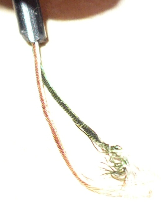
CGameProgrammer posted:Can someone tell me how to splice together speaker wire? I have headphones and attempted to shorten the wire for them but I can't figure out how to reconnect the two wire ends after cutting out a section in-between. When I strip the insulation, I get what appear to the naked eye to be one copper wire and one green-insulated wire, but macro mode with my camera reveals they're both woven metal wires with something else inside... this whole thing connects to my ipod via a simple 2.5mm jack so it can't be complicated. But no matter what I do, I can't get any sound to come out of my headphones. For future reference, fine-grit sandpaper can help you remove the epoxy that's coating the wires. You can also burn it off with a cigarette lighter. Edit: And that grey stuff is indeed fabric, for strength. Mill Town fucked around with this message at 10:41 on May 3, 2009 |
|
#
¿
May 3, 2009 10:34
|
|
|
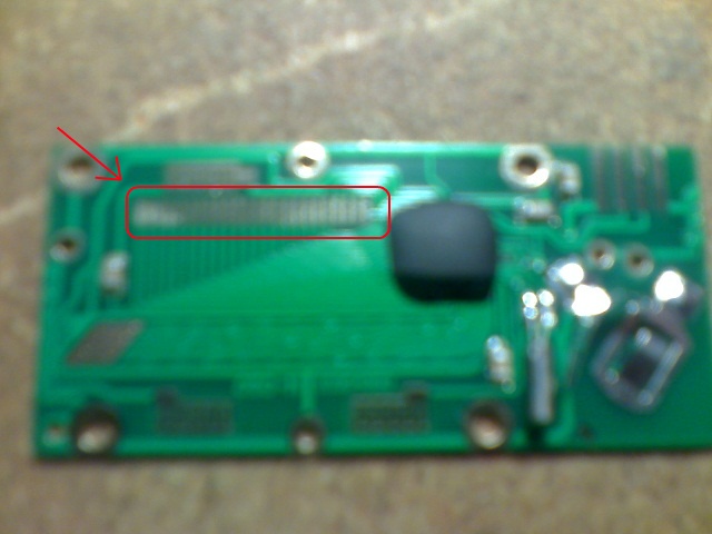
Delta-Wye posted:I would guess this is the LCD connection here: I've seen those before, the rubber strip actually has conductive bits in it. Try taking an ohmmeter to it and you should find alternating bands of conducting and nonconducting material. It will be next to impossible to rig up an extension that makes a good connection, though. Rather than extending the wires to the LCD, why not extend the wires to the Edit x2: That page you linked also explains how the data signal works. With some effort, you could probably write a program for an Arduino or other �C that reads the data and outputs it to an LCD or LED display. Mill Town fucked around with this message at 06:37 on May 21, 2009 |
|
#
¿
May 21, 2009 06:33
|
|
|
Tmavomodry posted:Does anyone have any source for cheap IR pass filter material? Exposed developed film negatives. Edit: apparently two layers give good results: http://www.davesastro.co.uk/equipment/irpass.html Mill Town fucked around with this message at 20:04 on Jun 11, 2009 |
|
#
¿
Jun 11, 2009 20:00
|
|
|
BattleMaster posted:I don't know how that function works, but you need to wait until the SPI module is finished before setting the I/O bit high again. It looks like all the function does is load the output register and tell the module to transmit, without waiting for completion. Yeah, looking at the datasheet, I think just waiting for SPIBUSY to clear is the best thing to do.
|
|
#
¿
Jun 19, 2009 23:47
|
|
|
SynMoo posted:Hopefully you guys can help me out! I'm trying to come up with a simple circuit and it's been awhile and I want to bounce my ideas off of you guys. Yeah, you can use a cheap 2N2222 for this. The Rat Shack should have them. Don't forget to use a resistor on the base. Somewhere around 1k should do the trick.
|
|
#
¿
Jun 29, 2009 16:17
|
|
|
SynMoo posted:Awesome, thanks! Yeah, the resistor for an LED on 3V will be pretty tiny. If you find your transistor doesn't fully conduct, lower the resistor value.
|
|
#
¿
Jun 29, 2009 19:14
|
|
|

|
| # ¿ May 1, 2024 09:18 |
|
|
ANIME AKBAR posted:I work at a company called alphamicron, whose proprietary thing is liquid crystal shutters for use in sunglasses/visors/windows/etc. You should talk to this guy, he's looking to do something like that on the cheap. Got any slightly damaged engineering samples around?
|
|
#
¿
Jul 7, 2009 04:05
|
|