|
HolHorsejob posted:I like Tricool MD1. Makes your chips smell like french fries or summer rain Skunkduster posted:To me, those are two very different smells. Does it depend on the material you are cutting? About 20 years ago, I was freighthopping along the Columbia River, from Portland heading east towards Idaho. Outside Hermiston, OR, my train entered Hinkle Yard. This is a big intermodal switching yard for Union Pacific. My train was heading into the heart of the yard to be broken up, so I bailed. I spent the afternoon watching yard operations and waiting for a likely-looking train heading east. Here's where I spent the night. It was between a Calpine power plant and a Simplot chicken mcnugget processing facility. It gets pretty cold in late September in eastern Oregon. That night, the chilly air condensed the moisture from the Calpine cooling towers. The wet clouds mixed with the exhaust from the chicken frying operation, producing a thick, oppressive fog of chicken mcnugget stench. It was horrible.
|
 #
?
Mar 12, 2024 23:14
#
?
Mar 12, 2024 23:14
|
|


|

|
| # ? Apr 28, 2024 10:29 |
|
|
ryanrs posted:About 20 years ago, I was freighthopping along the Columbia River, from Portland heading east towards Idaho.
|
|
#
?
Mar 14, 2024 00:33
|
|

|
wow, train hoboing in the 21st century, did you have a bindle? do you know the secret hobo signs
|
|
#
?
Mar 14, 2024 23:28
|
|

|
didn't have a bindle, but did hang out with north bank fred in dunsmuir
|
|
#
?
Mar 14, 2024 23:46
|
|
|
You were only half a mile down the road from NW Beef Express. Wait outside for someone to take a smoke break, slip in the door & you coulda spent the night cozy & snug inside a hanging beef carcass
|
|
#
?
Mar 15, 2024 02:03
|
|

|
Vim Fuego posted:You were only half a mile down the road from NW Beef Express. Wait outside for someone to take a smoke break, slip in the door & you coulda spent the night cozy & snug inside a hanging beef carcass Bubbles in the meat freezer: https://www.youtube.com/watch?v=kH73ygdzp48
|
|
#
?
Mar 15, 2024 03:43
|
|


|
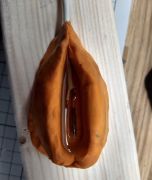
milled a very, very small lenin, just gotta trim and polish Ambrose Burnside fucked around with this message at 04:47 on Mar 16, 2024 |
|
#
?
Mar 15, 2024 05:11
|
|

|
That�s pretty fucken dope
|
|
#
?
Mar 15, 2024 07:19
|
|


|
Not to badmouth your work it looks pretty sweet, but like I know capitalism and monarchy are bad and all that but isn't Lenin also pretty bad too?
|
|
#
?
Mar 15, 2024 14:14
|
|


|
wesleywillis posted:Not to badmouth your work it looks pretty sweet, but like I know capitalism and monarchy are bad and all that but isn't Lenin also pretty bad too? quote:Please keep politics out of Hobbies, Crafts, & Houses. Many of us use our hobbies and houses as an escape. There's plenty of room for political stuff in D&D and CSPAM-let's save this forum for shitposting about our collapsing nightmare houses. This isn't really the space for debating or discussing how relatively bad or good Lenin/George III/Jeff Bezos are. For all we know Ambrose Burnside might be making a tiny bust of Lenin to piss on daily or use as a buttplug or somethin!!!!!
|
|
#
?
Mar 15, 2024 15:14
|
|

|
Kaiser Schnitzel posted:
|
|
#
?
Mar 15, 2024 16:44
|
|
|
CAMunist Lenin would appreciate the Finnish.
|
|
#
?
Mar 15, 2024 17:44
|
|
|
What's a good way to mill soft plastic? Or is there one? I tried to mill square holes (14.5x16mm) into a bunch of plastic electric boxes so I could use them as improv housings for ethernet keystone jacks. I don't mind them being proud of the walls as it's in an industrial setting with all the cabling run in open conduits near the roof and or stapled to walls. Anyway it just didn't want to work on this plastic, it just melted it and pushed the material around. Tried a 6 flute cutter and a 2 flute cutter at 1000rpm, two quire different cutters. In the end I chopped out square holes using woodworking chisels which was the right call. I am not sure some materials can be milled. Not sure what this was made of. Flexible plastic box.
|
|
#
?
Mar 15, 2024 20:12
|
|

|
Have you tried liquid nitrogen?
|
|
#
?
Mar 15, 2024 20:24
|
|

|
I know nothing about milling but that speed sounds way too high, too.
|
|
#
?
Mar 15, 2024 20:56
|
|

|
How much coolant are you applying? In any case, 1000 rpm seems pretty slow to me, for plastic. My experience with milling HDPE is that you have to make sure the tool is sharp, and that you're working at high enough speed and feed, especially if you're drilling.
|
|
#
?
Mar 15, 2024 21:06
|
|

|
Depends on the plastic https://www.curbellplastics.com/ser...ing-guidelines/ 980 is recommended for PET, for example, whereas many other plastics are suggested 920 to 1640 rpm, and PAI is 330rpm. e. per that page, and my experience, clamping is vital because the plastic wants to vibrate and if it vibrates it's just gonna get loads of friction and melt and not give you clean cuts/surfaces.
|
|
#
?
Mar 15, 2024 21:12
|
|
|
His Divine Shadow posted:What's a good way to mill soft plastic? You want the the sharpest one or two flute tool you've got, and you need to take an aggressive cut. Machining thermoplastic is all about reducing heat buildup. Sharper tools do more cutting and less rubbing. Fewer flutes give more clearance for the chips to get out without being compressed or dragged around. An aggressive cut will put more heat into the chip and less into the tool, and it'll keep the tool moving quicker so it spends less time heating up any single part of the stock. Look up something called an O-flute (oscar, not zero) tool. Get one of those, choose your speed according to the SFPM, and set your feed to achieve a high chip load of like .020-.030. depending on the plastic you could use water with a tiny bit of dish soap or WD-40 as a cutting fluid. Once you get it dialed in, machining plastic is a lot of fun. It goes so fast and sprays so many chips
|
|
#
?
Mar 15, 2024 21:17
|
|


|
Leperflesh posted:Depends on the plastic That chart is in ft/min, not rpm.
|
|
#
?
Mar 15, 2024 21:21
|
|
|
Dance Officer posted:That chart is in ft/min, not rpm. hahah welp here's one with RPMs (they're high) https://www.bu.edu/epic/lab-resources/ but these are harder plastics I believe I've done all my plastic "milling" with hand tools and I've found slow and low is the only way, but it's obviously different for milling
|
|
#
?
Mar 15, 2024 21:24
|
|
|
His Divine Shadow posted:What's a good way to mill soft plastic? Or is there one? I tried to mill square holes (14.5x16mm) into a bunch of plastic electric boxes so I could use them as improv housings for ethernet keystone jacks. I don't mind them being proud of the walls as it's in an industrial setting with all the cabling run in open conduits near the roof and or stapled to walls. Anyway it just didn't want to work on this plastic, it just melted it and pushed the material around. Tried a 6 flute cutter and a 2 flute cutter at 1000rpm, two quire different cutters. I've never had great luck milling plastics/composites but unless thats a huge fuckin endmill that sounds way too slow. You prob want a sharp 2 flute end mill at a higher than aluminum FPT. Check an online feeds/speeds calculator. Leperflesh posted:hahah welp These still seem slow. I'm guessing the .edu lab this is a part of has a mill with a spindle that is limited to 5k or 6k.
|
|
#
?
Mar 15, 2024 21:44
|
|

|
Sagebrush posted:Look up something called an O-flute (oscar, not zero) tool. Hey thanks for mentioning this, I'd never heard of these. I work for a plastic extrusion company and we often have to do fabrication. Been mainly using 2 flute endmills but these things look like they work better. Also yes, you need to be moving a lot faster than that. I think some of our programs are going 6k rpm with a 3/8 endmill. A Proper Uppercut fucked around with this message at 21:48 on Mar 15, 2024 |
|
#
?
Mar 15, 2024 21:45
|
|

|
Dance Officer posted:How much coolant are you applying? No coolant, didn't want a mess. This is an old manual mill that does like 2000rpm max. Based on other replies and esp. about vibrations I think the effort required to rig up the thing to be stable enough means I am better served doing it with hand tools as I ended up doing. I was just clamping the whole box lightly in the vise and the cover did vibrate. But that's about the level of effort I was willing to put into it. This plastic was real soft, I could bend the whole cover a lot, almost like rubber. His Divine Shadow fucked around with this message at 21:53 on Mar 15, 2024 |
|
#
?
Mar 15, 2024 21:49
|
|
|
CarForumPoster posted:These still seem slow. I'm guessing the .edu lab this is a part of has a mill with a spindle that is limited to 5k or 6k. I agree these look conservative. For HDPE I'd run the 1/2" endmill at 10k rpm and not think about it.
|
|
#
?
Mar 15, 2024 21:54
|
|
|
Seconding: O-flute (check the onsrud ones) endmill, high rpms, as heavy a cut your workholding can take, get the chips out of there. Never ever cut any metal with your plastic tools. Stay far far far away from polypropylene.
|
|
#
?
Mar 15, 2024 22:08
|
|

|
Yeah I would say another misstake I did was going slow and being careful. But with this material I doubt I would've made a better result. I think whatever this material is I won't try and machine it again. It's not like machining HDPE or Teflon which I have no problems working with on the lathe at least.
|
|
#
?
Mar 15, 2024 22:11
|
|
|
FYI rather than trying to look up an RPM for some material, you should be deriving it from SFPM, tool diameter, and chip load. 1. Look up the surface speed for your material. For HDPE vaguely recall a range from 500 to 1500 FPM, though for some reason I can't find a good clear reference online and my Machinery's Handbook is at school. Some materials are really forgiving of surface speed, some aren't. Worth experimenting to see what gives the best results. 2. Determine the spindle speed from surface speed and tool diameter. Say it's a quarter-inch tool. RPM = (sfm * 12) / (π * d). So that is (1500 or 500 * 12) /( 3.14 * 0.25) = between 7500 and 22,000 RPM. Very high for a mill, reasonable for a router. That's the reality when cutting soft materials with small tools, though. 3. Determine feed rate from desired chip load. For HDPE again I'd aim to not be below 0.010, and would push to 0.020 or even more if it was a light cut. Feed inches/min = RPM * number of flutes * chip load. So let's say it's a single O-flute, spinning at the low end 7500, 7500 * 1 * 0.010 = 75 ipm. Twice that, 150 ipm, if you have a two-flute tool. 4. Now you can determine the depth of cut from your machine power. Basically you can sink in as deep as your machine's motors and rigidity, and your tool strength, will allow. I'd start shallow, like .030, and increase stepwise up to the tool's diameter. Remember that you are feeding very fast. 5. If you find yourself in a place where even with coolant you are melting the plastic at these speeds (maybe your tool isn't as sharp as you thought?), and you can't feed any faster due to machine or tool limitations, then all you can really do is slow down the spindle to reduce the energy you're putting in. Keep the chip load constant by reducing the feed and speed simultaneously (or increase it by dropping spindle speed while maintaining feed). Since surface speed is only affected by spindle speed, this will reduce the SFPM below what is ideal, so the finish may change, or you may get weird looking chips that don't separate, and so on. But at least you shouldn't be melting the part anymore. 6. Realize that you want a bigger and more rigid mill, and a flood coolant system, and a spindle speeder, or maybe an air turbine... 
Sagebrush fucked around with this message at 23:39 on Mar 15, 2024 |
|
#
?
Mar 15, 2024 23:36
|
|
|
Sagebrush posted:6. Realize that you want a bigger and more rigid mill, and a flood coolant system, and a spindle speeder, or maybe an air turbine... Suddenly realize that you're now *boat money* into your hobby, but that's okay because at least you weren't dumb enough to buy a boat.
|
|
#
?
Mar 16, 2024 00:26
|
|

|
I used to cut out LDPE/ABS electrical enclosures with a 3018 GRBL and the above process is about correct. Your machine speed is as fast as the machine will physically move. Maybe 1000mm/m on a 3018 if you have it tuned right. Your spindle speed is 100%. Was that 8k RPM? 10k? 12k? Who knows? It's a cheap brushed DC Motor! 1/8" 1-flute upcut specifically designed for plastic, 40% stepover on the cuts. I got a 10-pack from amazon. Then put a similar piece of plastic in the machine, clamp it well, and adjust your depth of cut until it runs well. All my programs are on a thumb drive out in the shop, but I think I was doing .5mm per pass. Watch the thing cut. As soon as chips stop, slam the e-stop button, because you have about half a second until the plastic starts to melt and you break your cutter. If the plastic melts onto the bit, throw it away. For cutting holes and whatnot, I found that doing a peck-drill all the way through the material as the first step helped a lot. I suspect it gave the chips someplace to go when the cut started. Pockets were the worst, and I never really got slots to work all that well, so I just designed features that were at least .180" wide (.125 + 40%) if I had to go more than 1mm deep.
|
|
#
?
Mar 16, 2024 15:17
|
|

|
Sagebrush posted:FYI rather than trying to look up an RPM for some material, you should be deriving it from SFPM, tool diameter, and chip load. One thing to add, especially relevant for home machines taking lighter cuts or high speed machining approaches is to take into account radial chip thinning - because it's a circular cutter, the effective chip thickness/feed per tooth is much lower at small radial engagements than the linear chip load would suggest. It can lead to too low feed per tooth which leads to rubbing which leads to dull tools, poor finish, and vibration from unstable cuts.
|
|
#
?
Mar 16, 2024 15:35
|
|

|
When welding metal thats 1/2" thick or bigger, I know that you should be bevelling the edges to get better penetration, should you also be using bigger rods too? Like can you buy welding rods that are 1/4" thick or bigger for doing that kind of stuff? I'm not trying to weld anything that thick but I was thinking it seems like a waste to use 1/8" rods to weld really thick material. Although maybe 1/8" rods aren't too small for 1/2" but maybe for stuff thats 3/4" + in size.
|
|
#
?
Mar 18, 2024 17:28
|
|
|
Well they do go up to at least 3/4 but I think most situations end up with 1/8 rods and multiple passes. https://www.youtube.com/watch?v=QP3KnX4ywAM
|
|
#
?
Mar 18, 2024 18:03
|
|
|
Possibly naive question here: I bought a cheap die and handle set off amazon. Some of the dies are much smaller than the handle: And there are some dies the retaining screws don't even reach. Am I doing it wrong? Is there some inner adapter I don't have? Is it just cheap and bad and doesn't work?
|
|
#
?
Mar 18, 2024 18:26
|
|
|
Vim Fuego posted:just cheap and bad and doesn't work
|
|
#
?
Mar 18, 2024 18:39
|
|

|
Thanks, I'll return it for a good set
|
|
#
?
Mar 18, 2024 18:39
|
|
|
There are different sizes of dies and yeah they each need to go in the proper size of die holder. It's very common for backyard mechanics to make an "adapter" (ring with a couple of set screw holes in it) on a lathe. They're a pain in the rear end because then you have to unscrew two sets of things to change out the die. Better to just get a handle that fits the size of die you're using.
|
|
#
?
Mar 18, 2024 21:59
|
|
|
His Divine Shadow posted:Well they do go up to at least 3/4 but I think most situations end up with 1/8 rods and multiple passes. Yes, 1/8 is most common. I just made a double sided butt weld 1" plate to a 1 1/4" plate for a machining fixture. It was about 8 passes each side with a 33% bevel using 1/8 7018 rods. If I cared about 100% penetration, I would have bevelled closer to 50% and gouged out the root after doing a couple passes on one side.  I think the bigger rods are more for automated welding but almost all of that has been replaced with dual-shield or submerged arc for industrial production.
|
|
#
?
Mar 19, 2024 01:43
|
|

|
wesleywillis posted:When welding metal thats 1/2" thick or bigger, I know that you should be bevelling the edges to get better penetration, should you also be using bigger rods too? Like can you buy welding rods that are 1/4" thick or bigger for doing that kind of stuff?
|
|
#
?
Mar 19, 2024 03:02
|
|
|
Hadlock posted:So a fellow goon has picked up and been storing an engine for me 500 miles away (and almost a year ago) and is going to drop it off Saturday ryanrs posted:I bet it's faster to slap something together with 1/4" bar than mess around mitering square tube, finding longer bolts, etc. The flat bar is probably also lighter. wesleywillis posted:In addition to what ryanrs said I think I also see some angle in there as well. Angle is good poo poo for various applications like this. ryanrs posted:Pretty sure that angle is just two pieces of flat bar. Help me design an engine stand Block measures approx 13" wide, 20" tall, 36" long from rear mounting point to front engine mount. And then in the rear the oil pan drops down 5" and ~2" in the front so I've modeled a 13 x 25 x 36" box. With the carb and exhaust manifolds the absolute widest the engine is, is 22" On the left here you can see a sort of orange frog with red eyes peeking out from the bell housing. There are two 1/2" grade 5 bolts here holding on the bottom half of the bell housing, that won't be used when I switch to a different bell housing (and adapter)  Near the bottom of a sort of horseshoe-shaped engine mount, stamped steel supported by an inch of very rough looking rubber, and more sheet metal, is the front motor mount, also held on with 1/2" bolts. The front mount is only held to the engine with some weak-looking 1/4" bolts that run from the sheet metal, through the rubber, to the other sheet metal. The "Feet" sit at a 15 degree angle  This is kind of the design I've come up with. The base is 24 x 40", so it's 24 x 36" with an extra 4" extension on the rear, where the caster will mount to. My thought with this, is that the center of gravity when we had it on the engine hoist, was right at the flywheel, and thus it's heavier at the back end, and I want to support it there for when I remove the bell housing/transmission and swap it with a 5 spd jeep bellhousing/transmission. The two taller uprights connected by the horizontal thing is the front, and the two shorter bits that don't lead directly to the caster with the steeper angle are near the flywheel. I would probably double-up with angle iron the part between the rear supports and the caster    Measurements are not exact, but it's accurate within +/- 1.5" which is about as good as I can get without unbolting things. Which I'd like to do after I have it on a more stable stand. I found some nice 6" casters with the right weight rating, they have a mounting footprint of ~2.4 x 3.5" so I'm thinking about using 2.5" angle iron for the whole thing. It's represented as flat bar but I think you can visualize a tray made out of angle with the other bit sticking up. Ideally this is not just a display stand, but also start and run it a couple of times For example here is a flathead straight six on what appears to be an 18x24" platform made from 1.5" tubing. In later videos he has upgraded it with a battery tray and a spot to mount the radiator https://www.youtube.com/watch?v=oj-xkUBLLCQ
|
|
#
?
Mar 20, 2024 07:06
|
|


 . This all kind of happened all of a sudden and trying to figure out what to do with it
|

|
| # ? Apr 28, 2024 10:29 |
|
|
I want to replace my lovely ugly floppy wooden staircase railings at home with nice, slender yet sturdy custom fitting steel ones. I plan on using mostly plumbing parts, thick walled steel tube and mandrel bends and such and weld everything together. I'll need to tack everything up in place, then I can bring the things to the workshop for dirty jobs like full welding, grinding, surface finishing and the like. But I'll need to tack weld at home to be absolutely sure it will fit right. There's hardwood floor nearby that I'd rather not make burn marks in. The stairs themselves will be resurfaced as part of this project but I'd rather not set them on fire, and ideally not have to re-paint the stairwell walls when finished since that paint job is recent and looks good. I have the option of using MIG or TIG, but I'd rather MIG, welding-wise, but MIG makes spatter. I'm thinking about ways of protecting walls and floors from burns - does anyone have any good ideas for this? I have a fiberglass welding blanket and I can buy more if warranted, but I don't think a single layer of that material would prevent a molten blob of steel from making burn marks in the floor. Leather would be great but not cheap and useless to me when finished, I'd need several cows worth to feel somewhat safe. Damp cardboard? Damp cardboard with welding blanket on top? Some type of product I don't even know exists? Or am I dumb and should choose TIG for tacking instead and have less spatter and smoke to worry about and buy some good clamps so I can fix everything in place so both hands are free? The only proper machine work I have planned are turning some flanges for screw connections to walls, floors and ceilings (all reinforced concrete thankfully) but I figured there's bound to be some welding experience ITT.
|
|
#
?
Apr 18, 2024 18:57
|
|