

|
The german manufacturer individual computers is still making accelerator cards for the A1200, considering it's new hardware that's a lot less likely to fail the price is ok. Even if I don't like that dude's nickel- and diming of everything he does and it's pretty clear that he doesn't give a poo poo about anything except money, his work is solid and quite frankly, you couldn't make such an accelerator much cheaper if you tried. See it that way, you're going to buy such an accelerator once and if you don't turn into an electronics junk hoarder that pretty much will be it. There won't be a faster model Amiga you gonna need for all that new software next year and even if all the pipe dreams of ARM-based accelerator cards and new FPGA implementations of existing CPU designs come to fruition, let's face it, nobody is ever going to write software utilizing it and you'll always be stuck with software written 20 years ago and possibly maybe installing NetBSD which probably still will be dog slow. I'm not sure I'd rely on any A1200 accelerator board out there to be honest, besides the Phase 5 and ACA cards they're pretty much all terrible or have a bad cost/benefit ratio if you buy them nowadays. The Apollo cards are the absolutely worst though, everything that company released was crap. The memory timing on Apollo accelerator cards is very aggressive which already means you'll need some good RAM from a good manufacturer which can deal with it. Then the programmed MACHs were pretty much hand-picked by their tolerances because of the very tight timing and generally adventurous programming and there's no guarantee one MACH chip running on card A will run on card B as a result, showing how solid their design truly was. If you have an Apollo card, try the following two neat little tricks to make your computer crash: Fill up your RAM Disk until it's full or put an LHA in there and just let the computer decompress it on a loop. I'll 100% guarantee you it'll crash after a short time. Terrible cards, broken by design and I don't think I would even want to have one as a present. The A1200 in itself isn't great in the design department either, I mean the A4000 is terribly designed but the A1200 isn't exactly winning a design price either. Noisy boards, Commodore/Escom mixing different revision chips together with external fixes that don't need to be applied, resulting in instability especially when accelerators are used, (granted, that stuff is fixable to a degree) the ever-present power layout problems that lots of commodore's designs have, the hot mess the AGA chipset is in general, etc etc... If you really want to get an accelerator board for the A1200, I wouldn't go past 020/030 personally. They're guaranteed to stay inside an energy/thermal budget the computer can deliver and give you pretty much enough performance to run all those legacy applications comfortably (stuff like raytracing/true color picture editing/databases and advanced scientific math stuff would of course profit from a 040/060 more but let's face it, doing that on a Amiga nowadays is masochism). With both 040/060 (I'm not even talking about PPC because that poo poo is just a ridiculous, with failure and regret filled wank in combination with the Amiga) you'll run into problems where the board layout isn't good enough to supply the card properly and comfortably with power, potentially causing stability issues and a new power supply won't even help there. It's less of a problem with the 060, although it's still a problem. Also with CPU performance starting at 040 the chipset (especially in the graphics department) starts to become an anchor for the CPU and your only financially viable upgrade route in an A1200 from there on is those PCI boards which honestly, are just a terrible waste of time and money. Going that upgrade route you'll eventually end up with a weird, frankensteined system made from expensive components which will still work a lot worse than a PC from that time with a similar hardware payload and will hardly have any software taking advantage of/supporting it. Yes, there are also Zorro boards but at the end of the day, it's really not worth the effort. The original CPU the A1200 has isn't even that bad, good enough for all the games for that system and even if you want to do serious applications it has enough firepower for most of them. The only big limitation is the lack of FastRAM and there the problem is tracking down a RAM-Card that isn't just as expensive as an accelerator card. The lack of FPU isn't really a problem as not that many programs take advantage of an FPU in a meaningful way. In fact, if it bothers you that much you can solder an FPU in on the A1200 board. There's a very obvious space on the board where a big chip is missing, a 68881 or 68882 will fit in there just fine and work as soon as you solder one in. It'll run at about 14 Mhz, just like the CPU. Be aware that if you plug in an accelerator card that doesn't have an FPU, the FPU on the mainboard will be disabled irregardless, so you can't have an FPU with an FPU-less accelerator card that way. You can also add a clock directly onto the board if you can find the chip needed. That being said, all "pure" RAM-expansions for the A1200 I've ever seen came with a socket you could install an FPU in and a RTC so I'm not sure how useful soldering one in is. I heard people say the 020 is crap and you need at least an 030 to do anything interesting, but that's bullshit too. The 030 basically is just a slightly improved 020 with a bit of cache and an integrated MMU thrown in, another thing that's useful but really not utilized in any way by most programs. I'd say on a clock-by-clock basis, the 030 is 10% faster than a 020 at best. Where it really shines in an Amiga is in combination with 32-bit FastRAM thrown in and the speed gain there is highly depending on the design of the accelerator card and it's memory controller. The ACA cards, although with a lower clocked CPU than similar Blizzard cards and other old cards really shine there and are not rarely faster than those old cards with higher clocked CPUs simply because the ACA cards have access to technology and especially RAM that simply didn't exist in that form back then. I said it a thousand times before and I'll say it again now, a CPU is ever going to be as fast as it's RAM and the ACA cards show this nicely. I had one, don't have it anymore, basically just got it to pick it apart out of curiosity and again, while I really don't like the general attitude of Schoenfeld his work is solid. Also as I see it again and again with people owning Amiga accelerators - If you can't think of a very specific reason to have 128 MB of RAM, you don't need 128 MB of RAM. AmigaOS is a very primitive (by modern standards) operating system that doesn't even know things like caching. RAM that's always empty might as well not exist and will do nothing but draw power and produce heat (and old DRAM is very current-hungry). If you always have a part of your memory empty on an Amiga, you might as well remove that memory physically, it won't do you any good or improve performance in any way. The reason I stress this is because in the quest for more RAM they won't ever need, people attach RAM-sticks (especially on A1200-Accelerators) which don't really fit with help of rubber bands and the like and not rarely end up physically damaging the card. On bigger accelerators people really like to put in double sided RAMs which basically come with double the chip amount and are usually not buffered, which while fitting physically, will put a bigger load on the bus and actually put additional stress on components of the card, possibly causing stability issues and potentially shortening the lifespan of the card. I'm not sure if all the cards out there are designed for being fully loaded down with dual-sided memory sticks, the 128 MB you can reach that way in many cases was more of an theoretical maximum and I also don't think any of the accelerator designers intended the cards to work after 20+ years. I've seen shot bus-drivers on defective cards and also cards which apparently had damage to their memory-related circuity and could only recognize a part or none of the installed RAM anymore and I'm pretty sure there's a connection. On my 060 Accelerator card inside the Amiga 2000 I only have 32 MB of RAM installed, in two one-sided 16 MB sticks. This is plenty for most things I do, as most programs written for this computer were written with a tiny memory footprint in mind anyways. Go for the highest density RAM you can find and only put in as much as you need. The less chips, the better. With the ACA cards this doesn't matter as the SDRAM that it's used on them is soldered on already and always comes in 128 MB as going for a smaller capacity wouldn't make any sense and the SDRAM-ICs barely need any power anyways. I know I sort of went off a tangent here but maybe this will be handy information for people who plan on expanding. In conclusion, even if I don't like the dude the ACA cards will probably give you the best bang for the buck in an A1200, if you like your retro computing with a side of brand new hardware.
|
 #
?
Dec 10, 2014 06:49
#
?
Dec 10, 2014 06:49
|
|

|

|
| # ? May 3, 2024 18:04 |
|
|
I know you're exited about Amigas but there's really no need to crank out these giant wordwalls when smaller posts will still say the important stuff. Amiga accelerators are very expensive and you don't need much more than an 030 unless you're hardcore about these computers. 030 cards seem to be the most common and as "cheap" as lower spec cards. Apollos are very fast but unreliable, Blizzards are middle of the road and often offer SCSI, and ACA cards are brand new, and some of the fastest in their category. But even an A1200 with just a 4MB card is a fun time on it's own. A setup that's probably as much as most people will ever need would be something like: A1200 ACA1230, 28 or 56Mhz Commodore 1942 or Microvitec multiscan CRT, or Indivision AGA board for VGA/DVI output to modern LCDs Compact Flash card adapter acting as the hard disc (may or may not be bought on ebay preloaded with cracked games and a stolen WHDLoad key) 3.1 Roms and Workbench FBlit, FText, other speed patches, or a full distro like ClassicWB That's still north of �350 these days, but it's an enthusiast's setup, I'd be tempted for a better IDE interface and a cdrom drive but that way leads to madness. For just playing games on the TV the A600 with fastram and a CF card is much cheaper and more appropriate. At least we're not Atari people. Completely standard falcons are about �700 now, and that's a machine that needs a patch loaded just to support changeable fonts.
|
|
#
?
Dec 11, 2014 04:11
|
|
|
I dunno, I kinda like the wordwalls, but I get what you mean.
|
|
#
?
Dec 11, 2014 15:40
|
|


|
Shlomo Palestein posted:I dunno, I kinda like the wordwalls, but I get what you mean. Me too. When talking about ancient tech like this, having the added commentary and context is super interesting.
|
|
#
?
Dec 11, 2014 16:08
|
|

|
Oh don't worry people, there's nothing in the world that'll ever discourage me from writing word walls or talking too much. It's good if some people enjoy them, it's also good if some people don't read them. Won't exactly ruin my day. My usual process is that I sometimes just think about something I saw or did the other day and then I just sit down here with my browser and start writing. My reasoning is hope that things and especially contexts don't get completely forgotten as it has already happened a lot regarding this technology. An interesting little factoid is that Sch�nfeld actually bought the schematics and source code (of the programmable logic, usually AMD MACHs with the accelerators we're talking about here) of the Apollo cards from the former manufacturer and by his own words "let them disappear into a drawer so nobody will ever build those bad cards again, causing trouble with his hardware and making people put their Amigas away". While I really question his noble motives and I think it was more of a thing of nipping potential competition right in the bud and also keeping old cards from being repaired and potentially improved upon (which probably is more or less impossible seeing how little room for logic in this old MACHs is, comparably speaking) I have to say that probably most of the former programming and design of those cards would not be that easily translatable to modern technology he uses, especially re:RAM so they probably did not have a big part in designing the ACA cards and the ACA cards can't really be seen as relatives of them. MACHs aren't made anymore, and AMD didn't just tell anybody the programming algorithms so even the programmers for those chips are expensive and kind of hard to come by. Also they're not RoHS compliant which means they can't be used in commercial manufacturing anymore, manly because they contain lead and other problematic things for the environment. Oh, also AMD didn't keep these algorithms to themselves just to be dicks, there are good reasons for a manufacturer to do that, see: bad programming devices. A bad programmer can really ruin your day, even with EPROMs, and a big manufacturer will want to make sure that the devices used to program their chips do so to specification, else it can ruin their name if the chips often get noticed as being dodgy and unreliable in circuits, even if the chips themselves aren't at fault. Also we are talking litigation here too. A badly programmed chip who suddenly doesn't work as it should can cost human lives depending on where it's used. Many moons ago when I still was an early twenty-something and not in software, I worked in a company which produced medical devices, and later in one which built medical autoclaves, which was more mechanical work. Even small mistakes and oversights can set off chains that certainly cause great harm or even cost lives and then there's heads' a'rollin', the whole chain up to the dude who cooked the soup in the cafeteria and put slightly too much salt that day the mistake was made. Even if it won't kill you, even bad/cheap EPROM programmers can cause you a lot of headache and I'm saying that as many of you interested in old technology are probably at least interested in programming an EPROM now and then and probably at least looked at programmers on eBay. A really common problem with cheap EPROM programmers is that they have bad voltage levels. What this can lead to is that the programmer doesn't manage to program the EPROM properly and will fail somewhere halfway through which is irritating but not that terrible. Much more insidious is that these programmers could produce an EPROM which seems fine in the programmer but can only be read at a voltage level the target circuit for the EPROM won't have, causing parts or all of the programming to become "invisible" with the "proper" voltage applied. This is a thing that happens. I won't get into the technical specifics why it happens because it's a bit hard to explain in a few words, but it is certainly something to be aware of when buying an EPROM programming device. Like with most other schematics and source code from expansion cards, the ones of the DCE/Phase 5 cards are completely gone. There was a big nerd-slapfight between the manufacturer/head of the company owning the rights and the german amiga community causing the dude to eventually turn his back on the Amiga altogether. I think he even claimed to have destroyed everything relating to Amiga technology at his company at some point, probably also so people wouldn't try to contact him anymore. He died a few years ago. HorseLord posted:FBlit, FText, other speed patches, or a full distro like ClassicWB FastRAM is actually quite a big speed boost in itself for an Amiga, potentially able to even speed up a standard 7 Mhz 68k up to 30% under the right circumstances and when the App is written to take advantage of it (most of them are), mainly because the CPU can work detached from the chipset and doesn't have to wait for memory accesses to the ChipRAM. Remember, internal CPU cache is either non-existant or pretty rudimentary. The biggest problem is getting one for the A1200 at least as they are exceedingly rare and the prices are often collectors prices, not really aligned to what you get for the money. The reason there are no homebrew solutions for the A1200 regarding expansions is that the slots that fit on the trapdoor edge connector aren't made anymore (and in fact, might have never been a standard part, I am not sure). The ones on the ACA cards are made specifically for them. For the A600, getting kipper2ks 4 MB RAM expansion (google him, the prices are reasonable!) is as far as I'd ever go with that little SMD-Mutant. I wouldn't bother with a CDROM drive these days anymore with widely available flash memory solutions, in fact I don't even have an optical drive anymore in my day-to-day PC, and with the right programs you can actually mount .ISOs in AmigaOS if you really need to. If I'd want to experience what AmigaOS really is about and truly learn something I'd also stay clear from things like ClassicWB as they will give you a very strange view on what AmigaOS is and also teach you nothing. Just get some WB 3.1 install disks, and spend a few days building your system, applying patches from the ground up and really and honest-to-god actually reading the manuals and guides that come with programs and patches. It's a lot like modding a Bethesda game and just like modding a Bethesda game, be careful with mods that don't tell you exactly what they do and don't overdo it, as it can lead to a very unstable and strangely behaving system. If you put a little thought into it you can get quite a nice and snappy system you'll know the ins- and outs of. I'd even say don't do what everyone else does and install a file manager and at first, just do everything with one of the Shell-replacements like ViNCEd and some of the patches like unixdirs. People familiar with unixoid systems like linux can and will pretty quickly feel at home with AmigaOS here with the right settings. Police Automaton fucked around with this message at 18:36 on Dec 11, 2014 |
|
#
?
Dec 11, 2014 18:33
|
|
|
Kipper's 4MB clip on card is pretty cool. I've got a patched 1.3 rom somewhere with the A600's scsi.device in it waiting for one of those cards. I was going to use my A600 as just an A500 on steroids that way but I lost interest, especially considering there'd still be no ways to get 1.3 to recognize the PCMCIA slot, so I couldn't get it on my home network without using the serial port. Shame, I like that cute little computer. I honestly only lean towards a cdrom drive on a 1200 because I've always wanted a setup with a shitload of peripherals and accessories. Like a 1260 card, a SCSI tower, external modem, printer, scanner, sampler, MP3 Decoder... A real 90s rich kid setup but without any tower conversion bullshit. I'd become some sort of beige plastic digital hermit and communicate to the outside world only through email and IRC. I did the whole roll-your-own workbench thing but eventually I got tired of it. On a non RTG system I'd just roll out something like betterWB. Saves time installing the same set of poo poo everybody needs like LHA and whatever.
|
|
#
?
Dec 11, 2014 21:53
|
|
|
this is where I post this right?   
|
|
#
?
Dec 12, 2014 19:55
|
|

|
atomicthumbs posted:this is where I post this right? A PDP-11 processor board? Now that's an oldie. I don't know anything about them google couldn't tell you much easier but the CPU is interesting (the big, white thing) in that they had immense Problems getting the chip design working. You can funnily enough still find the PDP-11 in nuclear reactors of all places, a little factoid some enthusiast made me aware of a few years ago. If it's true I don't know but honestly, I would not be surprised, seeing the 68k series and 486s still are everywhere in industrial settings and the demand is actually so high that a company started producing fully 68020-compatible clones recently. I didn't have any direct exposure to them ever so I can't really say anything about them, I just know that there are in fact collectors but I guess that shouldn't be surprising, should it. You have the rest of that computer too? From the date codes on the chips and the CPU it seems to be from one of the late models, that series started off in the 70s. Don't know a lot about them. Interesting side note about that board in particular, can you see how the lower traces going to the side connector are tinned and don't have a solder mask? These traces are put through a lot of mechanical stress when plugging and unplugging and it's a very common point of failure on boards such as this and even similar ones in more "normal" computers. The tinning is often done in order to reinforce the traces and make them thicker, so they develop fissures less easily. Even a trace that could still measure OK with a common multimeter can be thinned in a way that at 7 - 20 mhz it suddenly has a resistance of 1kOhm or more, making everything stop working. A really difficult to find problem and if you have an expansion card that doesn't do anything for seemingly no reason, it can be a worthwhile mod to do to it to try if it works afterwards, especially if the traces on the card are as thin as here. There's also some bodge wiring but that might be something they already got in in the factory. With boards as old as this and computer aided design in it's infancy, you see mistakes in the design of the PCB a lot more often than you do now, even in (back then) expensive and high quality hardware. Instead of throwing away all the PCBs, companies just went and rewired the missing traces in, as this was just a lot cheaper than throwing the PCBs away and making new ones, and signal integrity wasn't all that critical at slow speeds. That together with the tinned traces at the bottom makes me believe that board could've been actually repaired at some point because it stopped working and might have some interrupted traces, but I don't know. It might as well have been something serial they did. Interesting hardware! You could probably put some antique unix on it and use it as a power-hungry terminal or something.
|
|
#
?
Dec 13, 2014 16:56
|
|
|
As I had advertised kipper2ks expansions - I advertised them because at first glance they looked fine on his homepage and the prices seemed quite fair for what you are going to get. I did order myself a 4 MB RAM expansion from him for my A600 as you really can't make it much cheaper yourself and it barely needed a week to get over the pond but I gotta say I am not impressed. The PCB itself is fine, the layout and all itself is fine too from a first glance but the soldering work was really bad. The card didn't work out of the box and blindly suspecting the bad soldering job, I resoldered everything. (It works now) The Socket that clips onto the CPU isn't on straight, there were leftovers from tin stuck to the board which could've went under sockets in transport and caused shorts, the CPU socket itself is damaged on the inside (no idea how that happened, looks quite ugly though) and also apparently was nipped with the hot soldering iron in one corner on accident, and yeah, generally not impressive and also, like I said, didn't work that way. (The SMD components' soldering looked really uneven and I suspect the problem was with the RAM contact itself) It's soon christmas and all and he was quite delayed and short with his email replies (I told him all I said here now too) so he might be a bit stressed, but I could imagine some people take this advice I post here on blindly and might not be able to solder themselves so I gotta say from my perspective to be a bit careful with this. I know lots of other people bought from him and had only good experiences but I can only talk from my experience here. It's probably still fine to buy from him but having a soldering iron to iron out the rough edges (so to say) might be recommended. E: Oh, also the entire thing came in a normal plastic bag, not an anti-static bag. Yeah.. no comment. Police Automaton fucked around with this message at 21:33 on Dec 15, 2014 |
|
#
?
Dec 15, 2014 21:26
|
|
|
Seen worse.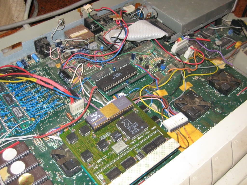
|
|
#
?
Dec 15, 2014 22:23
|
|
|
Someone really didn't have the right type of RAM there. Could imagine reflection issues on these lines, depending on speed. Usually systems below the 20-25 Mhz mark are really forgiving of such adventurous wiring though, as the signal speeds are so slow. Did that work reliably for a while?
|
|
#
?
Dec 15, 2014 22:34
|
|
|
So kids, marry christmas and all that. This thread is updated slower than I meant it to but for some reason this month went to one billion in the "things I've gotta do" activity scale and then I sorta ended up buying elite: dangerous on accident and yeah. Because I'm stuffed to the brim with food (christmas!) and moving is sorta painful I'm just gonna sit here and write about something. In fact, I'm going to touch a subject many people don't want to touch with a ten foot pole. (quite understandably!) - Power Supplies. Usually writings about this topic come with a wall of text with how dangerous mains voltage is etc.. I'm not going to give that disclaimer because I'm not going to advise you to do anything with mains voltage and if some post of some stranger on the internet who talks about power supplies inspires you to gently caress around with mains voltage and especially switching mode power supplies (which can become *very* unpredictable and dangerous when defective, especially old ones with just very basic security measures), you probably had your darwin award already incoming. You know, actually gently caress that I'm going to give you a disclaimer: Don't gently caress around with power supplies without knowing exactly what you are doing. People die that way. I personally know somebody who died that way who actually had somewhat of an idea what he was doing but didn't have the proper equipment to do it and was a big reckless dumb. Granted, this wasn't a normal computer power supply but they are just as deadly when handled wrongly. In that vein, if you absolutely positively have to gently caress around with a power supply, make at least sure there's somewhere nearby who can get help to you quickly if something happens. You don't want to lie dead in your hobby room for a few days. It stinks. Especially dangerous in power supplies are the big primary capacitors which can hold a charge way past 300V DC long after the power supply is switched off and disconnected from the mains, especially if there's something wrong with the power supply. These cap(s) can still be at a dangerous charge even a day later. Again, this stuff can and will kill you. Also, don't short the mains caps out with a screwdriver, they can explode or at least, get severely damaged. Power supplies are the heart of every computer and a very vital component that's often completely overlooked. It all starts and ends with the power supplies. A malfunctioning power supply can really ruin your day and cause massive damage, depending on how expensive your stuff is. Often a power supply that still might look ok to use is actually not and should be replaced promptly. For retro system aficionados power supplies are a big problem, because they usually suffer from aging effects a lot more than any other component in such an old system. Also, they might be external and have weird specifications, for which it might be difficult to find an adequate modern replacement. The 9V alternating current C64 power supplies offer, or a really strong and properly regulated +5V rail modern power supplies often don't have anymore, are two examples for such things that are rather unusual in modern ATX Supplies. The biggest problem in old power supplies are the filtering caps for the voltage rails. As opposed to the mains caps, the filtering caps see a lot of stress in their lifetime. Also, let's face it, the technology for caps was a lot worse back in the 80s and 90s and these things are 20-30 years old by now. Probably a lot older than the Designers ever thought of them to get. A very common failure mode in such old power supplies is the filtering caps shorting out, in turn shorting out that specific rail of the power supply. This usually isn't very dangerous per se as even very old power supplies usually have short circuit protection built in and the worst that usually happens is a trace giving away and burning up. A common symptom of this is very obvious: The power supply just doesn't seem to turn on. It might make a clicking noise. If you keep trying to turn it on, (I know that is the first reaction by many when something doesn't turn on, but try not doing this, it can actually make things a lot worse) eventually you'll hear a *plopp* and that'll be the end of that power supply for now. This can still actually cause massive damage to the power supply and even it's semiconductor components. A repair at this point is usually still possible if there isn't excessive burn damage inside the power supply. This really needs to be done by somebody who knows what he is doing though, as damage to some components might be less than obvious and the power supply might start to do strange and dangerous things in the meantime. If you absolutely and positively don't want to heed my advice (do heed my advice, your life and that of loved ones might depend on it!) and want to repair a power supply which already failed in a spectacular fashion, just replace as many components as possible in the direct circuit where the problem was, even ICs and yes, even ceramic bypass caps. At least that'll minimize the chance of problems later on somewhat. This is a very crude way to approach such problems and I wouldn't generally recommend it, but you see I'm just telling you this in case you are boneheaded so you don't google advice from some random Blog at least. Even when the caps aren't shorted out yet, they might, through aging, not work as well as filter caps as they once did. But what do filter caps even do? Without going too much into technical specifics, these caps have the main function of catching ripple current, which basically is "a residue" of the alternating current waveform from the input superimposed "on top" of the direct current the power supply has as output. It's just in the nature of how this stuff works and not something that can be completely eliminated, but is very undesired and should be as low as possible. Ripple can actively disturb the ICs of the system, causing anything from random crashes, video output disturbances and data corruption to severely shortening the lifespan of components, especially mainboard caps when the power supply caps aren't proper anymore. Excessive ripple can for example also cause this:  (This is a MACH chip on an accelerator card which went into latch-up, probably because of too much ripple on the +5V supply. The chip basically shorted out and heated up until it blew it's package. As the programming contents of this chip aren't known and it can't be replaced, the card is junk now) Another problem are the smaller caps dotted around the primary control circuit in the PSU, which for example are used as time base for a PWM-IC (e.g. UC3524AN, a classic you'll find very often in these old supplies). If these dry out because of age and change their properties, the power supply can again do very strange (and for the hardware connected to it often dangerous) things. How exactly all the small caps you might or might not have are used here and what the side effects could be is very design- and power supply dependent, so I can't really make generalized statements. On the mainboard on the old systems you find similar caps in voltage rail filtering applications that often still are fine, the simple reason they dry up in the power supply is that it's often much warmer there. You might gather from all this "Well gee whiz Police Automaton, I'll just replace all the caps like it's often advised for modern stuff that fails, like screens, and the problem will go away before it even started!" and then you wanna do something good for the power supply and will take the best caps your electronics supplier might have to offer, Panasonic, Nichicon, Chemicon - some neat-o Low-ESR series, ratet at 5000h@105C. Not only nice looking but reaaaaally reliable, that stuff you usually don't even get in high quality electronics by default, as big and mean as possible in order to filter that voltage even better. (insert Tim Allen Grunt here) Well that's a good idea in theory but in practice, it might be less so. You see, the switching mode power supply in front of you might be actually designed around specific values like ESR of the old capacitors, and new capacitors with vastly different values might actually do bizarre things to the control circuit, confusing it profoundly. You might end up with a circuit that oscillates wildly, (this is very dangerous for the hardware and difficult to measure without the proper equipment, you might notice by random components like resistors and ceramic caps suddenly catching fire and ICs breaking that usually never break) you might end up finding the voltage rails deliver voltages vastly out of spec, and other neat things like that, that might kill your hardware. Or, more generally, you might end up with a power supply that just doesn't work. While the obvious solution is to replace the old caps with new caps that have exactly the same values, in practice this isn't easy. First of all, you have to find out which values the old caps had exactly. You might get lucky and find datasheets on the internet, but more often than not for old stuff like this there often simply aren't any datasheets online. The company who made then might even have stopped existing before the internet became a thing. You can measure the capacitors you already have, but they might be defective/too aged and not give you the values they originally had. And even if you find out all the correct values, you just might not be able to find new capacitors that are that "bad". Not even kidding here. You still might go hunting for NOS (new old stock) parts but yeah... do you really want to replace your "old" caps with "new" caps that were lying around in some chinese warehouse the last 20 years? Without the proper precautions they will probably not even work. Granted, this is rare and my original A2000 supply here works just fine and dandy with the best, most modern low-ESR caps I could find. I do also have an A500 power supply which doesn't work with Low-ESR caps. Both power supplies are just one revision of many and it might be different for others for these specific computers. You see, it's not a straightforward thing, at least not as straightforward as some people might make you believe. I have written it down here because lately with the retro-wave, lots of blogs and somesuch have popped up with people which dispense advice without really looking at the topic at hand from all angles. Often because these people simply do not know better. Don't believe everything you read/see on the internet, not even what I just wrote, that easy. I'll also not take any responsibility if you get yourself killed with any of that info. It was just a general overview, I did not cover a lot of dangerous pitfalls power supplies have. You have been warned. Your best and only route as a hobbyist who wants to keep the old systems running without risking damage to parts might be to replace the power supply with something else entirely. Next post I'll cover what good power supply replacements are, and also what terrible power supply replacements are (hint: pretty much all ATX power supplies) Police Automaton fucked around with this message at 13:13 on Dec 25, 2014 |
|
#
?
Dec 25, 2014 11:17
|
|
|
So after the "Aaagh batteries leaking everywhere!" comments it gave me a kick to pull my girlfriend's A500+ out the loft and take a look at it, to see if it was suffering from this. Turns out it was:  Happy new year to me!  Looks like this combined with the two rubber-key 48k speccies I have which display garbage on boot mean that I'll be needing to: - learn to use a scope via the freebie 20Mhz old-school CRT analogue scope I got from $workplace - buying a USB digital scope (preferably which plays nicely with Linux) - getting a better soldering iron than the cheapo one I currently have (and previously used to melt a bunch of SCART connectors in an attempt to make a SCART->VGA cable using some instructions which needed only one resistor and some connectors) - learning to solder properly Been meaning to fix up some old hardware for a while anyhow, so this has given me a kick (but will more than likely be too much for me to attempt for a while without making it far, far worse). At least the speccies don't have batteries in them, the boards are a _lot_ simpler than the Amiga and the only custom chip they have is the ULA, so most chips are cheap and fairly easy to replace. Edit: The battery isn't in there now, but all the leaked gak still is until I can clean it up decently. Edit2: And yes I also realise now that putting it in the loft was a bad idea (and I had no idea about there being a battery in there at all until the posts in the retrocomputer gaming thread, so it's been caught earlier than it could have been!) legooolas fucked around with this message at 17:38 on Jan 4, 2015 |
|
#
?
Jan 4, 2015 17:35
|
|

|
Wow. I missed this thread when it originally got posted, this is good stuff. Going to sticky for a bit.
|
|
#
?
Jan 4, 2015 19:50
|
|

|
legooolas posted:
Thats not even that bad. You will probably want to replace the Trapdoor-connector for expansions though. You might painstakingly get that thing clean, but eventually you'll find out that that thing will just corrode away and fall apart regardless. Trust me on this. Replace the Gary socket, that LS244 and all the other passive and active components (U13!) that have green on them. Keep Gary though, you can clean the legs with a glass fiber pen (mentioned in earlier posts in this thread) until you see the copper. If they haven't broken off from that, the chip was salvageable to begin with. Then (carefully! Pay attention to not overheat the chip) reapply tin to the legs (you have to do this because the blank copper will oxidize in relatively short time and cause contact problems). Good as new! A logic analyzer wont really help you with this damage at least. Normally all you want to find out is if A is connected to B, meaning if a trace is corroded away or not. Even a cheap multimeter already does this good enough. A scope might help you in these cases were a trace is just damaged *enough* that the resistance is too high at "critical" signal speeds but yeesh.. I haven't seen it happen in something as ancient as an unexpanded Amiga. 20 Mhz (while better than nothing certainly) isn't really high-res enough here to begin with. Speccys and the like are interesting as they are, like you said, made almost entirely out of off-the-shelf components, compared to the custom stuff you find in the different Commodore products. They were cloned in the warshaw pact countries *a lot* because of that particular "feature", leading them to be produced in factories which didn't normally even do computer stuff and there being lots of different "kinds" of these faux-speccies. In the late 90s sometimes they swept over (with people leaving for the west) and you could see them here and there in germany on flea markets and such, nobody cared. I wish I would have bought a few, but they came with their language barrier. I didn't forget about "Power Supplies, Part 2" and that part will arrive soon.
|
|
#
?
Jan 4, 2015 21:57
|
|
 battery damage
|
Police Automaton posted:Replace parts, clean Gary I'm not proficient enough with a soldering iron to go leaping in to do this yet, so I shall practice on the somewhat simpler Speccies where they need it first. Will leaving it as it is for a while (without trying to use it!) cause it to continue getting worse in the meantime, even though the battery has been removed? Police Automaton posted:A scope might help you in these cases were a trace is just damaged *enough* that the resistance is too high at "critical" signal speeds but yeesh.. I haven't seen it happen in something as ancient as an unexpanded Amiga. 20 Mhz (while better than nothing certainly) isn't really high-res enough here to begin with. I was thinking of that more for debugging the unknown hardware problems on the speccy, as I find it easier to see what is going on and be able to see if the clock lines are wiggling in the expected fashion etc. The clock there is only 4MHz-ish for most of the components. I'm more of a software guy by day but hopefully I'll be able to become competent enough to help avoid some old hardware going in the bin  Police Automaton posted:I didn't forget about "Power Supplies, Part 2" and that part will arrive soon. Looking forward to it!
|
|
#
?
Jan 4, 2015 23:34
|
|
|
legooolas posted:I'm not proficient enough with a soldering iron to go leaping in to do this yet, so I shall practice on the somewhat simpler Speccies where they need it first. This is a very good attitude to have, I see often people approaching repairs that are a bit over their heads, usually resulting in causing damage they are mad about later and lots of frustration. I always recommend practicing soldering with junk PCBs. The small PCBs of defective harddrives for example are a great way to learn how to do SMD-Soldering. I have soldered quite a bit in my life and still, I have junk PCBs lying around I practice soldering with when I didn't solder in a while, before touching the important stuff. Even the entire process of fixing trace damage can be simulated by scratching traces and ripping off pads etc.. The upside is, if you can't get it fixed, it won't matter! Junk-PCBs with THT are a bit more difficult to find these days, but you can still spot them if you keep your eyes open. legooolas posted:Will leaving it as it is for a while (without trying to use it!) cause it to continue getting worse in the meantime, even though the battery has been removed? Yes. The corrosive stuff has formed a gunk with the protective solder mask of the PCB which you can see very nicely in the picture. Even after removal of the battery, the damage will keep spreading. When you google around, some blogs and forums might recommend you "neutralizing" that gunk with vinegar, the theory behind it being that vinegar is an acid while the battery "acid" is really a base. While that is technically true, this approach is rubbish and all you do in the end is pour organic acid onto your PCB. Nothing good ever came of that. What I recommend you is to remove the lower shielding and then to just wash your board in the shower. Yes, with the shower head on full blast, warm water and all. Don't be alarmed when some of the damaged paint/trace parts come off, if they didn't survive that, they had no function anymore and would've had to be removed anyways in the repair process. Then dry it off manually and let it dry throughly. You might want to remove the ICs first, (I gave some hints in earlier posts in this thread how to do this properly) but it's not entirely necessary. This will remove most of the stuff that's causing the trouble, but you should still do the repair soon-ish. These two-layered computers are basically always repairable, so don't worry too much. legooolas posted:I was thinking of that more for debugging the unknown hardware problems on the speccy, as I find it easier to see what is going on and be able to see if the clock lines are wiggling in the expected fashion etc. The clock there is only 4MHz-ish for most of the components. Keep the thread updated if you open up a speccy, I don't have one here but would be interested in what you do.
|
|
#
?
Jan 5, 2015 00:22
|
|
|
Police Automaton posted:Speccys and the like are interesting as they are, like you said, made almost entirely out of off-the-shelf components, compared to the custom stuff you find in the different Commodore products. Not just off the shelf, but broken off the shelf parts. The reason they offered a 16k and a 48k version was that 48k equals 16k of working ram chips, and 64k of half broken ones. Results varied.
|
|
#
?
Jan 5, 2015 13:46
|
|
|
Amiga 2000 goon checking in. SN 004519. Mine is still intact but I haven't peered inside for over 10 years now so I'm a little afraid to. For parts I have a 1000 and I might still have the 500 Mobo somewhere. I had the 1MB fatter agnes and a 68040 with a math chip, 8 megs RAM 4 of it 32 bit wide. I used to use it to write papers, play games, make animations and do some video toaster stuff. I still have the TBC but not the software to control it. I used to use the TBC as a color bumper when I did lightshows. I also used a terminal program and a 14.4 modem to dial up SFNet and my shell account at SFState. I miss the hell out of it though. I don't have too much to add except that 32bit wide RAM really amped up the performance, probably the best single improvement I made to it. I loved the RAM disk. Also thought it was cool if ever I started running out of system RAM, it would automatically use whatever spare memory was available in the Agnes chip, so upgrading from a 512 to a 1MB chip does more than just give you access to better soundcards. I'm going to make it my 2015 resolution to figure out what my Amiga needs.
|
|
#
?
Jan 6, 2015 23:22
|
|

|
legooolas posted:I was thinking of that more for debugging the unknown hardware problems on the speccy, as I find it easier to see what is going on and be able to see if the clock lines are wiggling in the expected fashion etc. The clock there is only 4MHz-ish for most of the components. I'm actually going into a little more detail regarding the oscilloscope business because this question comes up amongst hobbyists quite often. I thought maybe I kinda wait until you figure that out yourself (that's what I normally do, as such learning experiences are always better than just somebody telling you to not even bother) but other people often think the same way (that an oscilloscope is fine as long as it some value above the base clock of their "target" ) and might buy an ancient used one for way too much money they can't really use in the end. It's kinda strange what used oscilloscopes nowadays cost, a few years ago you basically got them for free and their resale value was limited. I guess more people picking up electronics as a hobby these days and all that, I do not think there are collectors. I'm not going to write a whole lot about it because it's a very technical topic that can't really be covered in a post on some forum (gotta get me a blog or something one of these days) and there are seriously good sources regarding oscilloscopes all over the internet, so I'm just talking about the speed here. For example, for a System that has a base clock of 4 - 7 Mhz, you realistically already want an oscilloscope that can do at least 50 - 100 Mhz. (and if you do a lot, even these will be not enough eventually) The reason for this is simple: harmonics. A digital signal is (ideally) square wave, so in a 7 Mhz signal in lets say an Amiga you have the fundamental wave at 7 Mhz, and harmonics at 21, 35, etc. Mhz. Practically this means the low bandwidth of your 20 Mhz Oscilloscope would work like a filter on the signal and that 7 Mhz square wave signal would actually look like a malformed sinus wave on the screen. You can tell there's a signal alright, but really not a lot more. You will not see glitches, jitter and all that interesting other stuff you would be interested in seeing and might actively be the root of problems you might have in your circuit. (and hoo boy, are these fun to track down) It's just too low res. And if you want to see a bump in the rising edge on that dataline caused by reflection that makes your 68k crash occasionally... just forget about it. If you really want to have any kind of quality to your readings and be able to see glitches etc., you need at least an oscilloscope that has about ten times the bandwidth of the fastest signal you are going to measure. There are no ifs and buts. A 20 Mhz oscilloscope is really at best be used to look at some lower frequency signals or the power supply, not a lot more. That being said, Oscilloscopes are IMHO mostly interesting if you are developing hardware and designing PCBs. When the hardware is already there they are in my opinion not all that useful to the hobbyist. Especially when you look at these old systems with an oscilloscope, all you do is wonder how they even work with all that noise. (Especially the C64 and quite funnily the very popular A1200, some board revisions are atrocious, the A2000 gets a honorable mention for some revisions having a serial problem with getting an NMI triggered sometimes because of noise, there's a workaround in the OS) A logic analyzer is much more interesting to see what the chips do and how they talk to each other. With a PC you can also record and analyze all that. I barely use my Oscilloscope anymore, not saying that it's useless but well.. like with every tool, it depends on what you wanna do. Police Automaton fucked around with this message at 01:01 on Jan 7, 2015 |
|
#
?
Jan 7, 2015 00:55
|
|
|
Police Automaton posted:Scope clock speeds, prices etc I did get this current 20MHz scope for free, so using it to see if it can provide any useful information to me isn't going to cost anything. Definitely useful to know that to get any useful really info out of a scope on jitter etc it would need to be a much higher resolution scope. I've only used them in previous jobs where I was making low-level software for boards (e.g. tools to flash boot images and one-time-programmable memory) which the company produced, and to debug customer boards which were having trouble working correctly, so my expectations of how useful a scope would be in getting visual feedback for debugging will be skewed by that. (And I don't know what sort of spec they were, but I expect "fancy") Police Automaton posted:Logic analyzers Logic analyzers are a whole world of cost higher than scopes though, yes? But being able to record the interactions on a PC is something that interests me, along with possibly using emulation/simulation to recreate failure effects on simple boards (just to help understanding what happens when, say, an address line is stuck). Police Automaton posted:Gotta get me a blog or something Definitely put this kind of info on a blog as well as here, it's exceptionally useful!
|
|
#
?
Jan 7, 2015 19:04
|
|
|
legooolas posted:Logic analyzers are a whole world of cost higher than scopes though, yes? I also just recently got myself an old 80ies scope. An old Tektronix 2245a 100MHz scope with a bunch of probes. It's surprisingly automated so it's easy to work with.
|
|
#
?
Jan 7, 2015 23:23
|
|
|
They sell extra things for that these days? I always do that with an multimeter. The times when you have chips dead permanently high or low on some pins you usually notice by these chips probably having shorted out internally and getting significantly hot(ter) than it is normal. You might even be able to catch a short in-circuit with your multimeter if you are lucky, but it's not a reliable method to search for errors. A very common place you see that in is various 74xx bus drivers when they were at the rear end-end of some steamy hotplugging action (Don't hotplug on old computers) or on cards that were put in the wrong way. But there usually such drivers end up getting connected to some 12V pin or something similar catastrophic and then you can notice by the hole in the chip. Two quite common things you see with repairs on such systems. Logic analyzers are great but yes, they are also expensive, although they have gotten significantly cheaper in the last few years the more they could rely on a PC doing the work. What you don't get on logic analyzers is the analog component, they'll just give you the zeros and ones. Well, usually, in a repair situation it's simple enough. What can you do anyways except replacing parts? In more advanced computers that implement some form of integrity checking on boot, you often already get error messages or at least some hint that something went kaboom. It's usually the more primitive 8 bit computers that will keep happily chugging on with half their ram shot or even entire chips missing and the like. It's because of their significantly lower level of integration, everything has a very specific function and some are just less important than others. A good example is the C64. (which is quite absent from this thread and I really need to talk more about) Old revision C64s have something called the Color-RAM. This is not an expression for some memory concept thingie, it's an actual chip. This normal, 4-bit RAM chip (1024 nibbles) just saves which of the 16 colors a symbol (line and row) is and tells the graphics chip which accesses it directly on every cycle. Remembering the color of screen positions, that's all that thing does. Hence, color RAM. Has nothing to do with the RAM of the system. You can physically remove that chip and the computer will still work normally, but every letter on the screen will end up being a different color and have the color change randomly in a rainbow-like effect because the lines are floating and picking up whatever noise is around. Doesn't bother the computer, it'll still function normally. Later Revision have the color RAM integrated into the PLA, which is a Commodore custom chip. See? Less and less chips doing more and more. Failure of something is usually catastrophic enough to make the entire thing stop working, which makes you ending up just going for the known suspects, often also the System gives you a hint what part of the boot process failed. Such repairs are not really all that interesting and I'd even go as far as to say that you usually don't need anything except a multimeter and a schematic when you are somewhat familiar with the system. Now, if you do want to do some reverse engineering, a logic analyzer becomes interesting as you can listen to many different data lines at once, which can become very difficult with even the most expensive scopes. You also already know the computer is working, so you don't need the extra detail a scope offers you regarding timing and voltage levels (if these are out of whack, you are already in trouble and the system isn't fit for some reverse engineering before repairs). You basically see everything that happens exactly the same way the chips in your system do. Quite sadly, many of the cheap logic analyzers (there are even some DIY projects) are not always suitable because they lack the amount of channels (the data is usually useless if you can't listen to every line on a bus, even with these old systems depending on what you listen to, you are quickly in a situation where you want to listen to 8 or 16 channels or more at once) their sampling rate is too slow (with USB streaming) or they just simply suck on the software end. Also you should be aware that you record everything that happens on a binary level, so you will end up with an absolute tremendous amount of data which is difficult to interpret if you don't know exactly what you are looking at. Some logic analyzers stream via USB directly to the PC, some have internal memory, but you'll always run into the situation where you'll get annoyed at how fast everything becomes full. Some logic analyzers do data compression on the fly, I'd look out for that. The cheap logic analyzers are usually more suitable for serial lines, where you only have two lines you want to listen to and the data comes... well in series. But if you want to snoop for example on the C64s 6510 CPU, everything is happening in parallel. I hope that tidbit of information is helpful. Please don't get the impression that a logic analyzer can replace a scope or vise versa, they are just different tools for different jobs. Having both of course is the best. E: Also ATX Part 2 still coming and this will really come as it's a topic very dear to me. Afterwards I'll go through some drawers and look at some old hardware.
|
|
#
?
Jan 8, 2015 00:47
|
|
|
If you are a fan of pinball/arcade restoration I'd recommend watching arcadeuk's videos. http://youtu.be/KyBHcIahIMo He goes into huge detail on how to fix old hardware.
|
|
#
?
Jan 9, 2015 18:41
|
|

|
theultimo posted:If you are a fan of pinball/arcade restoration I'd recommend watching arcadeuk's videos. I took a short look. When you are struggling with desoldering something that has been soldered in for 30 years, it's usually because of the impurities the soldering tin accumulated on the surface because of the elements, probably something these arcade machines have to deal with quite a bit, especially moisture. Instead of just turning up the soldering iron higher, struggling and potentially being left with a damaged PCB, it's advisable to "refresh" soldering joints with fresh soldering tin (with integrated flux) before desoldering. If even that doesn't help, you can use some Rose's Metal. Rose's Metal is an cheap, easily available eutectic alloy out of Bismuth, Lead and Tin with a low melting point of ~ 100 degrees celsius. (eutectic for our purpose basically means it has a very "narrow"and reliable melting point) It's a lot like the commonly known Material sold as "Chipquik", just that Chipquik (probably, I do not know)has the much more expensive Iridium instead of Bismuth and has an ever lower melting point through that. Rose's Metal is used for its properties in fuses and you can certainly solder with it in cases where you want something to desolder itself under specific temperatures and I have seen it used in security measures in devices working with much heat. I do not know if I need to specifically warn, but please do not use Wood's Metal when you see it somewhere and might think it's a good idea. It has an even lower melting point and similar properties, but contains the very toxic Cadmium (Bismuth isn't poisonous) and it's dust is also easily inflammable in air. First you apply lots of flux with a flux pen to the solder that gives you trouble, then you add a generous helping of Rose's Metal and the parts you struggled with fall out by themselves basically as the bismuth overwhelms and mixes with the roughly 50% Tin/50% Lead mixture that's usually used in old boards like this and stays in it's fluid state for very long. It's very gentle both for the desoldered component and the board and you can work with a low temperature. This all for THT-Components, but also works great for disoldering SMD stuff and is a lot better than hot air. Another thing those videos brought me to - if there are contacts to be crimped, crimp. The appropriate tools for crimping are pretty expensive but it is worth it and even with crimping tools as priced as low as 30 Euros, you do get acceptable results with practice. Even if you see it a lot in old hardware but especially with everything regarding power, never solder wires directly onto the contacts/PCB. Why is easy to explain: through capillary action the copper strands inside wires will "draw" the soldering Tin you use, leaving them inflexible and brittle right around the end of the cable, where you usually also have most of the mechanical stress. When you then subject them to mechanical stress (by plugging/unplugging) these now tinned copper strands can develop breaks and thin out the wire in places. If there's are a lot of Amperes flowing, in the worst case this can bring the cable to heat up in these spots and even burn. It doesn't matter if it's just five Volts. Even 10 ampere on 5 Vols are already 50 Watts of power. The blacking he experiences with some of the Molex contacts that transfer power doesn't happen through that, but the metals of the contacts in the plug and the contacts on the PCB connector reacting with each over over the years, developing a thin film which doesn't conduct very well and ups contact resistance. Increasing heat (the power that doesn't "make it over the gap" basically turns into heat at the contact) blackens the contacts further, upping contact resistance etc. until the connector catches fire basically. If the plastic parts of the connectors aren't brown yet, you just can clean the metal parts with a glass fiber pen until they are shiny and they will be good as new. If they are browned, I'd replace them because they will be brittle and not form a neat and tight connection anymore. A telltale sign of this is weirdly low voltages you can't explain. Which brings me to another thing I saw in some video of that link up there, (and where I stopped watching) for the love of god and all that is holy, please do not cut parts out of Molex KK connectors (which in systems around that age, are often used to deliver the different voltages and have to carry considerable amounts of Amps). Even if the part you cut seems to be reasonably small, the connector then isn't mechanically sound anymore and you don't want a connector delivering lots of amps that doesn't sit snug and tight because you'll run into the same effect I just mentioned up there. That's why these connectors close so tight and are so hard to pull. You want that. If you cut around on it you'll just end up with something that causes you trouble down the line as plastics aren't really long term stable to begin with and the connector will probably start to malform. These connectors aren't even that great to begin with and there's a reason you don't see them nowadays much anymore. Also, if you do lots of electronics and pride yourself into having a Youtube channel on fixing old hardware, please at least wear an anti-static wrist strap. It's the least you can do when handling stuff like this. Lead by example and all that. When you discharge into something you might get lucky enough that the discharge is caught by some passive components on the board, you might also be unlucky enough to break an important chip that's hard to get and replace. It's avoidable and the straps cost not lots. Granted, stuff like that happens rarely and I sometimes forget to put on my strap too like a person, but I do most of my work in a room where the floor is made of stone and I am almost always barefoot. Still, never make a habit out of that. This old stuff is way more touchy regarding these things to begin with. Ideally you also have an ESD mat to work on. I know, I talk myself often that you don't need an electronics lab to make repairs and what I say now sounds differently, but these things really are not expensive. I know videos are always more interesting to watch than reading a wall of text but I think sometimes in videos you always run the danger of not delivering important information for the purposes of making it more entertaining. I'd also never make videos personally because when I talk English I sound like Schwarzenegger. That's how you can read all my posts in your head from now on. Police Automaton fucked around with this message at 20:48 on Jan 9, 2015 |
|
#
?
Jan 9, 2015 20:46
|
|
|
Thank you for all this cool info about working with older electronics. It's really neat to read about. Police Automaton posted:I know videos are always more interesting to watch than reading a wall of text but I think sometimes in videos you always run the danger of not delivering important information for the purposes of making it more entertaining. I'd also never make videos personally because when I talk English I sound like Schwarzenegger. That's how you can read all my posts in your head from now on. \ 
|
|
#
?
Jan 10, 2015 00:27
|
|

|
CuddleChunks posted:"DON'T EXPOSE THE COPPER!"
|
|
#
?
Jan 10, 2015 07:00
|
|

|
Hi folks, I thought today I'm gonna deviate from my routine in this thread somewhat and make it more picture heavy, as I sort of did a little soldering today and set up a temporary working area (No soldering on old Hardware though). I'm gonna go ahead and tell you first that you'll not see an ESD-Mat in the following pictures, but just a sheet of paper. Now you might say "Hey, you first went into that guy for not having one and now you do the same, you are a big phony and Lowtax I want my $10 back" that's all right and true, but currently I'm sort of a soldering nomad in my own apartment as I'm setting up my little e-lab room anew and also do some other assorted renovations and currently this place is basically a big mess and quite honestly, I don't know where my mat went. Not all that important as I'm also getting a different workbench but hey, still. Not a good excuse but there it is. Also I'm sorry if the pictures aren't up to snuff, I once got this iPad I took them with as a present from a business partner and quite frankly, iPads are not great devices to take pictures with in my opinion, even though if the resolution is quite good. First a thing quite important. The Storage of THT-ICs. If you have old computers, you probably do collect some here and there because some ICs get increasingly more rare on the market and increasingly more difficult to replace. Old stuff bites it sometimes and then you have no replacement, which could be quite annoying. There are also some people who collect them, like stamps, just because. Whatever you do, you should store them properly. Many people use these little tubes you often get your parts in from the electronics part suppliers, but they are not a very appropriate ESD-Protection, as they will happily pass a charge through themselves and everything contained within. The only thing they don't do is build up a static charge by rubbing against something. They are ok to use by an electronics supplier who only needs some basic ESD-Protection and doesn't really care much when sometimes something needs to replaced, but they are not a good permanent storage. Styrofoam and Styrofoam wrapped in tinfoil (also very popular) is NOT a proper way to store such parts and will not protect from anything.  (That's some EPROMs, some custom Amiga-ICs and I think a handful of SIDs, also a socket which doesn't belong there, the small green PCB is a Guru-ROM I think, didn't check. You'll also notice some chips are labeled MOS while some others are labeled CSG. They're made by the same company, MOS Technology, a company bought and owned by Commodore. CSG stands for Commodore Semiconductor Group and that labeling was used later on on the ICs. You can also see here how old these chips are by reading the datecode. For example the big chip in the lower left, if you can read it, "5090". It means it was produced in the 50. Week, of the year 1990. You might spot some chips on there that are older than you!) The thing I use to store my chips are big mats of static-dissipative foam. (not to confuse with conductive foam, which is more expensive) They are carbon-impregnated (that's why they are black) and are conductive because of that, just with a very high electrical resistance. Black static dissipative foam is permanent and can be reused for a long time, contrary to the pink foam you might have seen some new hardware come packaged in, this foam is not appropriate to use as it has a shelf life and goes bad when exposed to air. The mats in itself don't provide shielding so I place them into big ESD-Bags, which sort of work like a Faraday cage. Packaged like that I put them into big containers (I have quite a few of them) which can be sealed and have a few of these small silica gel bags within, to trap some of the air moisture (which is not good for ICs). The last bit is probably not strictly necessary, but can't hurt. The silica bags only cost a few cents and you can "refresh" them by baking them in the oven at 80 degrees Celsius occasionally. You can get appropriately-sized ESD-bags and these foam mats for very little money from many electronic parts suppliers and it is certainly worth it. I also took a few pictures of my A500 out that has some bit of a background with me. I once got this computer from a junkyard (yes literally) in a time where you could get a nice A500 in Germany for about ten bucks. Nobody really cared about that thing, it was lying outside and was positioned in a way where it could rain into the case from the exposed side slot (which had it's plastic cover missing) which it certainly did a few times, as it's metal shield was completely rusted, so was the keyboard backplate in parts. Also something heavy was dropped on it at some point, which made the plastic case break in one place. The inside of the case was filled with cobwebs and insect carcasses. I did some on-again-off-again restoration work on it which on the board mostly consisted of taking out the completely rusted cinch-connectors, one capacitor which rotted away and replacing all sockets which were filled with something what I can only describe as black gunk. I also cleaned all the legs of the ICs and it looks quite good now I think. You can get pictures of A500s all over the internet, so mine are probably not that interesting but still, maybe I can say a few things.  Yes, the A500 was nicknamed Rock Lobster and so that you will absolutely get the reference, they also included the band name on the PCB. I can't even fathom what kinds of lawsuits that would cause nowadays, but it was a different time and computers were nerd poo poo nobody else except nerds cared about. I think most people know that song from that family guy joke. The B-52's were sort of an acquired taste for me. The more you listen to them the more you like them. It's weird. There were many revisions of the A500 board, 6A was the most common one I'd say.  Part of the serial interface. Serial was to us back then what USB is to you now. They are in a sense similar that the communication happens between devices serially (d'oh) but RS232 is not a bus, so the communication is point-to-point, between two devices. "Paula" the custom chip in the Amiga who handles sound also handles the serial port, which you can also connect only one device to. (remember, not a bus) It had sort of it's downfalls, mostly the slow transmission speed and the voltage swings, which made the entire thing sort of unreliable and difficult to implement on a hardware level, even though I'd go ahead and claim most of the unreliability happened by devices being cheap crap and not implementing the protocol properly. The both chips you see here, MC1488 and MC1489 (Motorola designs in this case second-sourced by Signetics and Texas Instruments) are the level shifters. Paula communicates serially on TTL-Level (0 - 5V) and these chips shift that to to the voltages needed by RS-232. One "drives" the line outgoing, one is the receiver. They then interface both with Paula. You'll find these chips in virtually any serial hardware imaginable of that time and they can still be bought new for cents, I doubt they are produced anymore though, more common nowadays in industrial applications is the MAX232 which does alone what both these chips do. These chips absolutely LOVE dying in weird ways which makes you end up in situations where you can establish a connection but weirdly not receive data anymore and such nonsense. They also act a bit as a buffer when you get the idea to do some steamy hotplugging action so that you at least don't destroy the more expensive custom IC behind them, although that's not their intended function of course. Lots of hardware designs were sensible enough to put them into sockets so that you can switch them easily when they do break. Commodore wasn't.  Here you can see the place in the back where the Capacitor just sort of corroded away. I removed it. You can also see a discoloration on the board besides it and I have no idea what that was about, it didn't come from the capacitor and the paint doesn't seem to be damaged. It actually looks like it was made that way. Also replaced the Cinch connector for composite. Also you can see I replaced the old double spring contact sockets for the ICs with gold-inlayed precision ones. I like those better as they don't tend to get loose over the years or have the chips shake loose with vibration or movement. They are not very good if you switch ICs often though and if you put chips in them that still have soldering tin on their legs, you'll positively destroy them. It's not a replacement I would do by default but more on a by-case basis. In this case I replaced them all because the original ones were pretty much rotting away. There are also terrible single spring contact sockets which are absolute crap and should always be replaced when you encounter them. With old hardware as this, bad contacts become your worst enemy. There's also no CPU and Kickstart-ROM on this board yet. I will not talk much about the custom ICs here at this point as I think the post will get too long then.  Here's a closeup of the area. The long black thing is a Hybrid, called the "VIdiot". It's basically a primitive DAC (digital to analog converter) which converts the digital RGB signal to analog RGB which then is sent to the video port behind it. Amigas RGB-video runs at 15 kHz horizontal scan rate (as opposed to the 31 kHz VGA is all about) which makes it sort of an Odyssey to find a good modern screen that works with the Amiga. The Composite output here is black&white only, that's all the VIdiot can do, although it's very crisp and nice for text only. The VIdiot is also used by the A2000 and a custom Commodore thing that's impossible to get nowadays, so don't break it. (It's very easy to break an edge off of it on accident) Also yes, Foxconn was already around back then.  Here you can see the main system oscillator and the expansion port. 28,3571 Mhz in this case, for a PAL-System. The entire timing for the System is derived from this and there were always people who tried to overclock the system by switching that oscillator for a faster one, only to find that suddenly, the refresh rate at the video port was higher, music played faster and even the disk drive motor ran quicker. It's not a good idea. The Side expansion port is basically the CPU bus. It was used on the A500 mainly for the A590. An external Harddrive expansion which came in it's own case and had a (by default) 20 MB harddrive, you just plugged it into the side. It also had optionally up to 2 MB of FastRAM. I have one, I wanted to take some pictures, but I'm afraid I can't reach the box where it is in right now. I told you my place is a mess. Also note the nice test points on the connector. You could easily solder some Pins in there and then whack your logic analyzer in there and listen to the CPU. Very "hack-friendly" one would say nowadays.  The main System ram up front at the botton. The A500 came with 512 kb of RAM by default. Beginning with Rev 6a, Commodore used higher density RAM and laid out the Board to be compatible to up to 1 MB, which also the newer Agnus could address. (The big quadratic chip, basically the heart of the Amiga) They never equipped the Board with 1 MB by default though, preferring to nickel-and-diming their customer base by selling 512 kb RAM expansions with clock. (The A500 didn't come with a hardware clock either, just like the Rasberry Pi. Unlike the Rasberry Pi though, there was no Internet to set the system clock with) There were many 3rd party RAM expansions, some more questionably build than others and it's probably the most common expansion you can find in existence. Here on this Board I added the additional 512 kb in, you can tell by the sockets I soldered in. Even had to get the ceramic caps myself, you can tell by my bypass caps (the yellow things) being soldered in more nicely than those by Commodore. Production values were never great with them. If you ever want to expand a system with RAM (no matter what kind) with old stuff like this, always be mindful that especially shabby DRAM-manufactures (just like OKI here) often had RAM that didn't quite live up to the rating that was printed on it. 80 ns RAM for example sometimes could barely do 90 ns before producing errors. So when in doubt, never mix and match RAM of different manufacturers like I did (I used Hitachi RAM with OKI ram, both not exactly stellar manufacturers back then). Even if the speed rating is the same, it might just not work. In my case here, it didn't matter. All the RAM was marked as 100 ns (which is already slow) and even 120 ns for Amiga chip ram would be fine too. To the right you can see the Trapdoor expansion port, where you'd plug the RAM-Board in.  The other side of the board, just to give you a general overview, there would still be a lot to learn but I think this was enough words about the A500. In the background you can see my hand desoldering pump. Never do what I did there and only noticed after taking the pictures and leave it with the spring pressed in, it'll break it eventually. Some retrogaming channel regulars might remember the 168-pin PGA Socket I switched on that one expansion card and took pictures of. Did that all with the ol' hand desoldering pump, no need for a desoldering station with enough practice!  Here's a rather rare accelerator for the A500. You'd plug it into the CPU socket and plug the original CPU on the accelerator. With a switch (somebody soldered wires and a switch directly to the pins up there, I didn't) you could then switch between the faster CPU (020 here) and the original CPU, depending on if you wanted to run software that wouldn't run with the faster CPU or not. The quadratic chip in the socket is the FPU, up to and including the Motorola 68030 that still was an external chip. Interesting about Motorolas FPUs was that they could run with an asynchronous frequency to the main CPU (driven by it's on oscillator for example, missing in this picture from it's socket) and also that there could be several FPUs for one CPU. I have never seen a design taking advantage of the latter, though. Neither the 68881 nor the 68882 were stellar performers, even for back then, they could be used for every CPU between 68000 - 68030 though. This Expansion comes with it's own 32-bit (4 bit x 8) FastRAM (4 MB in this case) which is important as else the CPU would have to wait for the slower System memory for accesses, basically destroying every speed advantage.  Another expansion, with a rather rare 16 Mhz-rated 68k CPU. This and the other CPU both run at roughly 14 Mhz though on these expansions, not 16 Mhz, like they could. Why? Because the Amiga as a Sytem runs at ~7 Mhz and when interfacing with the slower rest of the system, 16 Mhz would be a lot more difficult to pull off engineering-wise and basically would offer no speed benefit. Just doubling the base clock is much easier. This particular expansion doesn't come with any FastRAM and is therefore pretty useless in itself as the CPU has to wait for slower RAM access before being able to fetch instructions (no cache). A lot of these expansions which go directly into the CPU slot are so generic design-wise and non-Amiga specific that they would work with any 68k based System.  Now this is an interesting one. The large chip on the side is an NEC V30, which is compatible to Intel's 8086, running at 8 Mhz. This expansion goes into the trapdoor slot of the Amiga 500. What it would basically do is that it would turn the Amiga into an XT PC via software switch. There were similar expansions for the bigger Amigas which were basically PCs on an expansion card and would run pretty disconnected from the Amiga as their own contained Computer within the Computer. This one here is different as it would basically "take over" the Amiga (switch off AmigaOS) and use it's custom chipset and the Amigas CPU to emulate the PC Hardware. It could even do Soundblaster and Adlib emulation and everything up to and including VGA (even though VGA only in monochrome IIRC). It could also use a potentially connected Harddrive if you gave it it's own FAT-formatted partition, and PC disks with the Amiga floppy drive. It comes with 1 MB of RAM which also could be used by the Amiga as 512KB RAM expansion/512KB RAMDisk when it wasn't in use. I remember that it would speed up graphics operations very much when the Amiga had a faster CPU installed and also could use FastRAM as System RAM if the Amiga had any. I also remember it being very compatible with any program, OS and game I tested it with. Quite an interesting piece of kit from a dutch company if I recall that correctly. I remember the developer of it ran off to Brazil many years ago and opened up a diving school or something. I never took apart how it worked on a low level. Well so much for today, I hope this was interesting to some. Word walls about ATX power supplies incoming soon. Police Automaton fucked around with this message at 13:00 on Jan 13, 2015 |
|
#
?
Jan 13, 2015 07:24
|
|
|
Hi! The retro gaming thread sent me with a capacitor question. I got my mitts on a Sharp X68000 from Japan. I'm still waiting on a video converter to show up so I haven't powered it up yet. The notoriously faulty power supply has been rebuilt and the SRAM battery has been replaced so I figured it would be good to go. However, I was recently advised that I might need to re-cap the entire thing because it was built in 89 and those capacitors are probably living on borrowed time. There are certainly lots of places online that recommend a full re-cap no matter what like the warning at the top of this page. I spot-checked some components and all the capacitors look good but I'm not sure if a visual inspection will cut it with 20+ year old capacitors.  So I guess I'm looking for a second opinion. Should I go ahead and plan on a full re-cap or would that be over-kill at this point? If the answer is a full re-cap I'll probably have some follow-up questions about how to shop for the correct capacitors from places like Digikey. Thanks in advance. Edit: Regarding this quote from the OP: Police Automaton posted:In future posts I want to address what the best way of replacing capacitors is, the plethora of options regarding replacement types, and why THT capacitors usually don't need to replaced while SMT capacitors should almost always be replaced. I'm guessing THT means through-hole tech? All the caps in this machine are through-hole so maybe I don't need a full re-cap? Seems like every time I find I "yes" answer I find another "no" answer shortly thereafter. ")
wash bucket fucked around with this message at 16:56 on Jan 14, 2015 |
|
#
?
Jan 14, 2015 15:04
|
|

|
THT means through hole technology, yes. The proper answer is, it depends. You would have to measure capacity and ESR, with an old school ESR-Meter you could do that in-circuit and at least get a hint if a capacitor is failing or has failed, but I wouldn't recommend it. The proper way is to desolder a capacitor and then test it, at which point of course it would make more sense to insert a new capacitor instead of putting the old one back in, considering the low costs. Capacitors in these old systems have the job of stabilizing and filtering the main system Voltage, usually +5V. Some of them might have to deal with +12V for audio op-amps and similar purpose. There is no point of load regulation usually, like in a modern computer. Usually these capacitors aren't very stressed in their lifetime and in many cases, the systems still boot up when you remove the capacitors without replacing them. (I don't advise that though, as they catch much of the general nastiness of the power supply, and the systems also might also not work reliably in this fashion) Most capacitors of that time and age are still fine, so I'd say generally no, it is not necessary. The difference would be if there's a known weak spot in the design or capacitors commonly used in these systems that are known to fail, then I would of course replace. With the smaller THT-Caps that don't have a breaking point at the top I'd look around the legs if they have leaked there and not for bulges on the cap itself, as that is their general weak spot after all these years. You'll rarely see caps like that just bulging out of nowhere in a system that wasn't used for many years. They rather either dry up or leak through their seal at the legs. Leaked electrolytic caps can be different to spot with the naked eye under less-than-perfect lighting conditions, so a hint can be dull looking soldering joints around the caps in question and a smell of rotten fish when the system is warmed up. You should also visually inspect the system now and then. I am blindly guessing here that all your capacitors will still be fine though and will probably be for at least another ten years. I have an old FM/AM-Reciever/Amp combination here, from Technics. I use it as kind of a stereo/Headphone-Amp with my PC and old systems, so I use it every day. It's manufacturing date is 1979. All it's caps (even the small ones) are still fine and I actually measured them. I also have a few C64s here from the mid-80s where the same applies. I do inspect them now-and-then though, and yes it would be easier to just replace them, but it is interesting to see how long they last. If you still really wanna replace them, look out for capacitors rated at 5000h @ 105C from a known brand. I like to use panasonics, because I can get them cheap. There's no actual need for such robust capacitors in such old systems, but electrolytic caps are so cheap that there's no need to save those literally two cents and get lower quality parts either. With capacitors being a lot better than they were back then, you could probably get away with caps with a lower capacitance rating, but it shouldn't be necessary. Caps with the appropriate voltage ratings nowadays are much smaller than they were back then, so I would advise to look at the datasheets and get caps with the highest voltage rating that fit into the places where the old caps were. It'll look more "original" and they will also last longer. All this doesn't mean that all THT caps ever used in computers last forever either, though. Of course there's the capacitor plague from early this century I won't talk much about, as that's rather a case of industrial espionage gone wrong, not a failing of the technology of caps in itself, but caps from around that time on mainboards I wouldn't trust much longer than about 10 years, even with caps that weren't victims of the plague. The reason is the local voltage regulation for CPUs and heightened requirements on the power infrastructure on systems starting at about late Pentium/ early Pentium II. Caps in such circuits do see a a bit of stress and do age quite a bit as a result, if you have stability problems and odd behavior with such an not-quite-old-but-still-old system, it might be worth it to replace the THT-Caps with newer ones. You could also go overboard and use Tantalum caps, which is something some people might recommend you. Their only advantage is that they last basically forever and can not leak, as they are dry. Some people will say to never use tantalum caps as they will all explode 5 seconds after being soldered in and are unreliable, that is rubbish though. While it's true that early-gen tantalums did explode for seemingly no reason and tantalums generally can cause a lot of damage when they start burning, if you use them correctly, they will be fine. Correctly in this case means having a power supply that's up to snuff and doesn't puke out excessive ripple, and also have a generous voltage derating of 50-70%, like the manufacturers of tantalum caps recommend. (which means, using a 10-16V rated tantalum cap on a 5V rail) Rush-in current and all that other scary stuff that's sometimes mentioned in combination with tantalum caps you also don't really have a problem with in these old systems. But here's true what is always true with replacing one type of cap with another: You should know what you are doing and have a general idea how the cap is used in the circuit. Another possibility for THT-Cap types on such old boards are solid state polymer caps, the type of caps used in modern electronics and mid-90s serverboards when you needed higher capacities. They can't leak either and usually can be use as a direct drop-in replacement for electrolytic caps. They do have a shelf life though and as the technology isn't that old and widespread it's hard to say how their shelf life will add up in reality compared to the test conditions they get their hour rating in. With solid caps there's no advantage in derating, so scaling them as closely to the voltage they are used with as possible is absolutely fine. It might be difficult to get polymer caps with high capacity, and usually because of their vastly superior properties, you could in many cases probably put a capacitor in that only has 50-25% of the capacity of the original capacitor and it would work just as well. Again you need to know what you're doing here and solid state caps for a system that old are complete overkill, just as tantalum caps already are. Just covering them in case. Just like tantalums, they are also pretty expensive too. So I hope this covers most of the questions regarding THT-Caps or tl;dr: No. Much more important: What kind of power supply do you use?
|
|
#
?
Jan 14, 2015 18:55
|
|
|
Police Automaton posted:Most capacitors of that time and age are still fine, so I'd say generally no, it is not necessary. The difference would be if there's a known weak spot in the design or capacitors commonly used in these systems that are known to fail, then I would of course replace. Ah, you can't imagine my relief. Thank you very much for taking the time to walk through all of that. The only really notorious point of failure with the X68000 computers are the power supplies and mine was re-built by the previous owner within the last two years. I haven't visually inspected that part yet but according to the previous owner it has all new capacitors, diodes, and transistors. The outside of the power supply had a note written on it in marker with the date the work was done so someone was in there doing something at least. Police Automaton posted:So I hope this covers most of the questions regarding THT-Caps or tl;dr: No. Much more important: What kind of power supply do you use? I don't know much more about the power supplies beyond what's in this wiki. Here's a schematic for it in case you're able to gleam anything from that. Again, thank you very much for your reply.
|
|
#
?
Jan 14, 2015 19:32
|
|
|
McCracAttack posted:The only really notorious point of failure with the X68000 computers are the power supplies and mine was re-built by the previous owner within the last two years. I haven't visually inspected that part yet but according to the previous owner it has all new capacitors, diodes, and transistors. The outside of the power supply had a note written on it in marker with the date the work was done so someone was in there doing something at least. That's pretty much true for all old power supplies and isn't really a design failing of the power supplies in themselves, but more lies in the nature of the thing. I did cover old power supplies and why/where they fail most often in this earlier post, if you are interested. In short, it just lies in the nature how these things work. McCracAttack posted:I don't know much more about the power supplies beyond what's in this wiki. Here's a schematic for it in case you're able to gleam anything from that. Again, thank you very much for your reply. Did take a short look at the schematic, seems pretty bog standard and also has all the security features you should have in such an power supply, of course what I can't gather from a schematic is how the power supply is actually put together and that still could be terrible, but I have the feeling it'll probably be on the level. If you ever run into a situation where the power supply actually fails it would be no problem to replace it with an equivalent industrial power supply, as there is absolutely nothing unusual about it. Really like the power switch that's switching both phase and neutral, really nice attention to detail there you often don't see in things of that age. In old power supplies the switch actually is a very common point of failure and it's worth it replacing it sometimes. I would feel a little concerned why he felt the need to replace diodes and transistors, it might be that the power supply already failed at one point and then close attention has to be paid if the repair was done properly, looking at the schematic it might also be because the parts already looked a bit toasty because of the heat they had to endure. In the latter case, it's not strictly necessary to replace such parts, but it doesn't hurt either. If the computer ran with the repaired power supply for a while, then probably everything is OK. EDIT: Fixed the link to my own post, sorry I'm not good with computers Police Automaton fucked around with this message at 22:02 on Jan 14, 2015 |
|
#
?
Jan 14, 2015 21:44
|
|
|
Caps talk reminds me that I have a European model 2 Sega Mega Drive which no longer outputs sound. It's been a while since I last checked, but I'm wondering if this is something I can repair, and where I'd need to start looking. Cursory Google searches just directed me to audio quality optimization guides for the MD2 but no repair guides or anything like that. As far as I can tell the actual output connector is fine.
|
|
#
?
Jan 16, 2015 13:28
|
|


|
hmm I should really check my Mac IIci and Sony HB-F700 for battery leakage. Would the thread be interested in some pictures of the internals of these machines? spankmeister fucked around with this message at 14:18 on Jan 16, 2015 |
|
#
?
Jan 16, 2015 13:45
|
|


|
Smoke posted:Caps talk reminds me that I have a European model 2 Sega Mega Drive which no longer outputs sound. It's been a while since I last checked, but I'm wondering if this is something I can repair, and where I'd need to start looking. Cursory Google searches just directed me to audio quality optimization guides for the MD2 but no repair guides or anything like that. As far as I can tell the actual output connector is fine. Maybe you can sniff something out here. Check the service manuals at the bottom.
|
|
#
?
Jan 16, 2015 13:53
|
|
|
Smoke posted:Caps talk reminds me that I have a European model 2 Sega Mega Drive which no longer outputs sound. It's been a while since I last checked, but I'm wondering if this is something I can repair, and where I'd need to start looking. Cursory Google searches just directed me to audio quality optimization guides for the MD2 but no repair guides or anything like that. As far as I can tell the actual output connector is fine. Obligatory question: Did you try a different cable? First thing (after the cable) I'd suspect in a system without SMD caps is the connector itself, even if it seems fine. Especially stuff like this was usually owned and used by kids, which often means nonstop ripping out and cramming the connector into the plug (often blindly) leading to broken soldering joints directly at the connector (especially in the case of these lovely mini-DIN plugs which I assume the device has considering all the outputs going to the same place). Doesn't have to be really visible at first glance, If you can solder, resoldering the connector(s) at least does not hurt. Just put a little fresh tin on there. That's the first thing I'd do before I go more in depth. In this schematic I see two ways to get sound, first there's a pretty standard OpAmp circuit for the Left and Right channel (which are then lead to two pins on the A/V Connector) and then at the end of the circuit there's active mixing of the Audio (again via OpAmp) and that's also routed to a Mono Pin at the A/V Connector, so I'd find out first what the cable you have does. spankmeister posted:hmm I should really check my Mac IIci and Sony HB-F700 for battery leakage. You should really check out your Mac IIci as it has SMD caps and they probably have leaked by now and of course, at least I am always interested in high res pictures. Police Automaton fucked around with this message at 02:41 on Jan 17, 2015 |
|
#
?
Jan 17, 2015 02:14
|
|
|
Police Automaton posted:Obligatory question: Did you try a different cable? Cable's already been swapped out with a different one with the same results(first thing I tried, and it's a mini-DIN), and the way the sound died leads me to believe it's not the cable or connector (cut out after playing for a while at first, the interval shortened until the sound didn't work at all from power-on). I opened up the MD2 itself back when it happened and the connectors all looked good internally. Never gave it more than a glance at first. I haven't tried it for about a year or two and it's currently not at my place, and my trusty soldering iron is loaned out to someone as well, so I'm gonna look in to it when I have those around again.
|
|
#
?
Jan 17, 2015 12:59
|
|
|
Now this is why you practice before you repair things (this being a Neogeo MV-1). Though how you can gently caress up with a DIP package is beyond me. Notice how the RAM further away is at an odd angle. I'm not sure if he tried to remove the chips and gave up half way through or what he was doing. Also note the miss coloration, you don't actually see the ground plane with the naked eye but I took that picture with a flash. I wonder what sort of solder he was adding which flux actually dissolves the solder mask. This is another reason to always clean up after you with isopropyl alcohol.
|
|
#
?
Jan 19, 2015 12:43
|
|
|
My camera is being repaired right now so no pictures yet, but it turns out my sony HB-F700P MSX2 is constructed using two single sided boards. Old skool.
|
|
#
?
Jan 19, 2015 12:45
|
|
|

|
| # ? May 3, 2024 18:04 |
|
|
Smoke posted:Cable's already been swapped out with a different one with the same results(first thing I tried, and it's a mini-DIN), and the way the sound died leads me to believe it's not the cable or connector (cut out after playing for a while at first, the interval shortened until the sound didn't work at all from power-on). I opened up the MD2 itself back when it happened and the connectors all looked good internally. Never gave it more than a glance at first. You should find out if the cables take the sound in stereo or mono, as both is possible with this console and could help with locating the problem. If the manufacturer used sub-miniature THT-capacitors for audio decoupling it's possible that one of these dried out, which would speak for the sound failing on the Mono-pin and that your problem lies somewhere in the vicinity of the mono-output. When you take a look, try getting sound from the left and right channel pins. That the two channels fail exactly at the same time in the same fashion because of a dried out cap is rather unlikely. The LM324 op amps used here can be run with a single rail supply and that's exactly what is happening in this system (basically the cheapest way to do it possible) if you had problems with voltages here the entire system wouldn't work so that's out and I doubt one failed (although you might want to check their temperature of IC9, if that one had a complete failure this would make all three audio pins not work, although it is unlikely). The only other thing left is the custom IC where the sound basically comes from and it might have a cold soldering joint somewhere when it gets warm enough. It is an SMD package, so failing everything else you might take a shot at re-soldering that. Else there isn't really anything left. I'm still betting on a contact problem. Contacts become your worst enemies in these old things. spankmeister posted:My camera is being repaired right now so no pictures yet, but it turns out my sony HB-F700P MSX2 is constructed using two single sided boards. Old skool. Are they really single sided, or do they have a plane that consists entirely of ground on one side (which still makes them technically double sided)? This might have been done to keep the noise down. The thing with many double sided PCBs from that time is that it actually really wasn't good enough often although considerably cheaper. (still is) As busses got wider and you had a lot more tightly packed and faster signaling going on, you just couldn't get away with it anymore, you at least needed the dedicated voltage and ground plane to keep the noise down. That being said, lots of even very old boards have incredible problems with noise and often rely on their metal case/RF-Shielding to work as sort of additional grounding. Wow went off on a tangent there but anyways: If any of you ever have stability or boot problems with a system that comes in metal shielding or a metal case while tinkering around with the mainboard outside of it, try putting it back in (and also screwing it in with all the screws, as they make the ground connection) before trying anything else. It might already solve your problem. Sometimes such problems can be solved by putting adhesive copper tape onto the backside of the board, you can get that in any electronics store or places where guitars are sold. Be very careful to not short out anything, as especially on Boards with THT-Components it's very easy to poke holes into the adhesive part and make contact with the copper part. This should only be considered a temporary fix at best. It's also a serviceable way to make old PC-Soundcards less noisy, but the better way here is having custom metal plates made and screwing them to the sound-hardware in question if possible. This doesn't cost a lot but requires some planning and a PCB where you can screw stuff to. Also please don't get the impression from all that that multilayer boards are immune to noise, up to and including Pentium era systems I encountered Mainboards that were only truly stable inside the computer case. A very usual symptom is strange trouble with ISA/PCI-Cards here. Pinguliten posted:Now this is why you practice before you repair things (this being a Neogeo MV-1). Though how you can gently caress up with a DIP package is beyond me. Notice how the RAM further away is at an odd angle. I'm not sure if he tried to remove the chips and gave up half way through or what he was doing. Also note the miss coloration, you don't actually see the ground plane with the naked eye but I took that picture with a flash. I wonder what sort of solder he was adding which flux actually dissolves the solder mask. This is another reason to always clean up after you with isopropyl alcohol. This is what you get when you have an soldering Iron that's poorly temperature controlled or plain too weak. You need a lot longer for everything as the PCB (usually the grounding plane) carries the heat off, and eventually the heat from the soldering iron just burns the soldering mask away and also damages the glass-reinforced epoxy the boards are made of and yet you still didn't manage to remove the soldering tin as it didn't become fluid enough. People love to buy these cheap soldering/desoldering stations from china but they're usually not a good investment as there are no spare parts and they barely manage to keep the temperature you set them to. Your soldering iron should have at least 40W of power, a settable temperature range (a digital temperature display is very nice, but not strictly a must, the soldering station should have some feedback of when it has reached it's temperature though) up to and including 450 degrees celsius and should best be made by Weller (American) or Ersa (German). You can get very nice stations from these two manufacturers starting at ~100 Euros new (or sometimes even cheaper used, it's ok to buy those used) and they will basically work forever. There are also many kinds of fancy tips but I always return to the standard 2 mm "wedge"-tip. On top of that a plain old hand-operated desoldering pump (preferably made of metal) and some desoldering wick plus a flux pen and bob's your uncle. As long as the tool adequate, all it needs is practice, practice, practice. In my experience fancier tools here are usually only really of advantage when you do this stuff in series and daily, everything else can be replaced by experience. Most soldering flux (especially the one added in to cheap soldering tin) is actually lightly corrosive and should always be cleaned off directly after soldering, as it will also trap the air moisture from the surroundings with time which also isn't exactly great for the components. It doesn't cause this amount of damage though. It's always best to look for "no clean" soldering flux added, even if it costs a bit more. Usually the soldering tin in question specifies which kind of flux it contains, and then you can google if it's corrosive or not. F-SW-23 is for example Flux that's lightly corrosive and you encounter on the regular in cheap soldering tin. The Name is actually sort of a code, and quite honestly I could explain all that but it's easier to just read the Wikipedia entry on it in case you are interested. Flux can actually be quite harmful to your health, and it's best to not breathe it in directly or have prolonged skin contact to it. Always wash your hands and only solder in well-ventilated areas. When you solder for a living, you usually have a hood for the fumes, but if you solder now and then, I'd say this is not strictly necessary. (but then again, I'm not a Doctor) Jeez. Lots of words. I hope it's interesting to some anyways. Police Automaton fucked around with this message at 03:00 on Jan 20, 2015 |
|
#
?
Jan 20, 2015 02:42
|
|