


|
TerminalSaint posted:Quick question for those more knowledgeable than myself. I'm just getting started with this stuff, and made a dedicated push to talk button with a Teensy 3.1 I'm fiddling with. It works as intended, but I figure everything could use more LEDs. As a best-practices thing I would use two pins for that, unless you're short on pins. Use the button to tell your code what to do, and use the LED to show that your code is doing it.
|
 #
?
Oct 8, 2014 18:50
#
?
Oct 8, 2014 18:50
|
|


|

|
| # ? May 28, 2024 03:29 |
|
|
The button actually worked fine just routed from digital to ground. I scavenged some strips of surface mount LEDs out of an old keyboard and they work as intended wired up per the diagram, sans diode. Which is odd, because the keyboard was feeding them 4.5 volts. I'm surprised they manage to light up on 3.3.
|
|
#
?
Oct 8, 2014 19:17
|
|


|
TerminalSaint posted:The button actually worked fine just routed from digital to ground. I scavenged some strips of surface mount LEDs out of an old keyboard and they work as intended wired up per the diagram, sans diode. They've probably got a 1.6V forward voltage, so that's enough. When I made a circuit like this, I just had the button connected directly to a pin and the LED connected to another pin that was turned on in software.
|
|
#
?
Oct 10, 2014 16:31
|
|


|
I'm having trouble adding a data logging shield (RTC+SD) to my arduino (uno) sous-vide controller and I think it's a RAM issue. The stock onewire library pushes it over the top; just including the Wire and RTC libraries makes it poo poo itself when I power it on. The Wire library by default creates 4 32 bit buffers and I was able to get it working for a while by editing twi.h (part of the Wire library) and reducing this to 8, and this solves the problem for a little while but then it freezes after a few minutes of operation (generally leaving the relay powered on). Commenting out the Wire/RTC stuff solves the problem and it runs forever happily. Any suggestions on how I might get around this, maybe with a lighter weight/standalone RTC/Wire library reducing the memory footprints of SD/SPI/OneWire/PID? I mostly just want to get some reasonably accurate time:temperature data on how it stabilizes to the setpoint for PID tuning so it's not the end of the world or a permanent thing and millis() would probably suffice but it's still a big pain in the rear end and I want to win  . .
|
|
#
?
Oct 11, 2014 19:12
|
|


|
Heya Goons... Thanks to Poxin for pointing me here, I guess I wasn't aware we had an arduino thread. Anyway, I would like to show off my ArduiNIX. http://www.arduinix.com/  Back in 2007/2008 my buddy and I set to work making an arduino shield that would take care of power and multiplexing for a nixie clock. He did the code, and I did the hardware, website, etc.  Trouble is, he moved on to another job and I am not a coder. So, my codebase is a little flaky I think, but it gets the job done. I have a forum with a small community that has posters who provide some code and things. People have added to the original code, but I am not enough of a programmer to comment on it. I am the art/hardware guy. Anyway, I just wanted to say, hey, arduino goons, here's my arduino thing. Hope you like it. 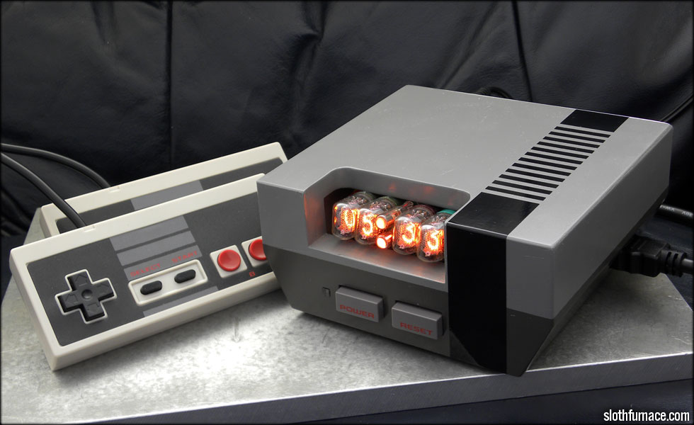
|
|
#
?
Oct 17, 2014 17:29
|
|

|
nonentity posted:Heya Goons... Aw, the shield's out of stock. Hopefully you get some more in soon, that looks like a fun thing to put together.
|
|
#
?
Oct 19, 2014 16:33
|
|


|
Mr. Despair posted:Aw, the shield's out of stock. Hopefully you get some more in soon, that looks like a fun thing to put together. I will, I planned on re ordering a batch of boards this week.
|
|
#
?
Oct 20, 2014 02:25
|
|
|
I'll preface this by saying I'm pretty new to the Arduino platform (and programming in general!) so what I'm attempting may be out of my league. I've been given bunch of weather sensors, including this wind direction/speed anemometer, that I'd like to attempt to interface with an Arduino to make a little weather station. Sparkfun make this weather shield which does pretty much everything I want and more, but according to the comments it's incompatible with my anemometer because it's pin-outs are wired differently to the sensors it is designed for. The wind direction in both my sensor and the compatible one are based on a 20k ohm variable resistor. Wind speed in both sensors is measured with a magnetic reed switch. Should it be possible for me to make an adapter/rewire the pin-outs to make my anemometer compatible with this weather shield? Alternatively, someone else has wired the same model anemometer as mine directly to an Arduino but has the data being output to an LCD. The sketch they posted has a couple of functions I'm not familiar with, but theoretically should it be possible to modify it to output the data over the serial monitor rather than onto the LCD?
|
|
#
?
Oct 20, 2014 02:49
|
|

|
Rozzbot posted:Alternatively, someone else has wired the same model anemometer as mine directly to an Arduino but has the data being output to an LCD. The sketch they posted has a couple of functions I'm not familiar with, but theoretically should it be possible to modify it to output the data over the serial monitor rather than onto the LCD? Yes, it shouldn't even be hard. Follow the data flow to the various lcd.print statements. They'll be very close to what you'll need to Serial.print. The biggest difference is that can't do the same kinds of cursor manipulation with the serial monitor.
|
|
#
?
Oct 20, 2014 03:17
|
|

|
Awesome, thanks! I'll have a crack at it and report back!
|
|
#
?
Oct 21, 2014 05:59
|
|
|
I am running into some problems communicating on the Serial bus; hopefully someone can give me some pointers... I've got an Arduino Pro Mini (3.3V 8MHz) connected to an ESP8266 chip; the ESP8266 responds to variety of AT commands. When I upload an empty sketch to the Arduino, I can open the Serial Monitor at 9600 baud, send the "AT" command and I recieve a nice "OK" string back. Now when I try to the same thing using this very simple sketch code:The strange thing is also when I disconnect the power to the ESP8266, suddenly the Serial Monitor is printing "AT" every second. But as soon as I plug the power back, the printing stops. I can also communicate through an USB-to-TTL adaptor without any issue so I know the chip is functioning fine. Any ideas what I am doing wrong?
|
|
#
?
Oct 22, 2014 19:45
|
|

|
Does the Pro Mini use the hardware serial port for the USB to serial interface? I have a feeling you're probably getting some conflict there if so. Try moving the ESP8266 to a couple free digital I/O pins and using the software serial library to talk exclusively to it: http://arduino.cc/en/Reference/softwareSerial You'll want to change the sketch to look something like:code:
|
|
#
?
Oct 22, 2014 19:55
|
|
|
Great stuff, thanks alot! I am now getting a valid response back; I had to send the "AT+RST" reset command first but afterwards I receive everything correctly. mod sassinator posted:Does the Pro Mini use the hardware serial port for the USB to serial interface? I have a feeling you're probably getting some conflict there if so. Try moving the ESP8266 to a couple free digital I/O pins and using the software serial library to talk exclusively to it: http://arduino.cc/en/Reference/softwareSerial You'll want to change the sketch to look something like:
|
|
#
?
Oct 23, 2014 06:11
|
|
|
How is babby made. Never really screwed around with Solar before. Ok for a solar powered Arduino in an average lighted room, not directly under a lamp what kind of specs do I need for 1) powering the arduino and 2) powering the arduino + tiny servo with very low load? I am thinking I need something with like 9v as panels drop in voltage when not in direct sunlight, and around what, 500ma? This 9v 350ma item seems to be the best bang for the buck I can find. Could I wire this up with two 5.5 1F capacitors to smooth out power draw from the servo(s)? It's abot $13 shipped. http://www.newegg.com/Product/Product.aspx?Item=9SIA40F1UY0345&cm_re=solar_panel-_-022-01CP-00020-_-Product
|
|
#
?
Nov 2, 2014 09:44
|
|


|
Hadlock posted:Ok for a solar powered Arduino in an average lighted room, not directly under a lamp
|
|
#
?
Nov 3, 2014 02:42
|
|
|
Hadlock posted:How is babby made. Never really screwed around with Solar before. You'll need a battery, it will not even boot with only a panel
|
|
#
?
Nov 3, 2014 03:15
|
|
|
But everything I've read says the arduino will pull 25-45ma, surely a 350ma panel can push 50ma? Or am I really dreaming? Servos pull at least 40ma each but I think, only when they're moving; it seems like a capacitor could help smooth that out based on a low servo usage scenario.
|
|
#
?
Nov 3, 2014 06:12
|
|
|
Hadlock posted:But everything I've read says the arduino will pull 25-45ma, surely a 350ma panel can push 50ma? Or am I really dreaming? The panel will only put out 350ma in full, bright sunlight. Even if your house is very well lit, you're not putting out nearly as much power as the sun.
|
|
#
?
Nov 3, 2014 13:48
|
|
|
How do I store a string of characters incoming from the serial port? I'm trying to find and store the $GPRMC string from a gps unit and am totally lost.
|
|
#
?
Nov 7, 2014 04:59
|
|

|
There are various methods, example. Almost any terminal program can connect to com ports and record serial data, any one of those should be fine. There are also numerous processing, python, and other language scripts which can do the same. Poke around and see what works best for you.
|
|
#
?
Nov 7, 2014 05:16
|
|
|
Parts Kit posted:How do I store a string of characters incoming from the serial port? I'm trying to find and store the $GPRMC string from a gps unit and am totally lost. Create a character array as a buffer, and make it as big as the largest string you expect to see. This needs to fit in memory so you have at most maybe 1000-1500 characters it can store (an Arduino Uno has 2k of memory, but you need to save some for program variables and libraries). Then create an index variable which is a number that will point to the next open spot in the buffer. Initially it should be 0 because spot 0 and beyond are open for new characters, but as you read characters from the serial port add them to the spot in the buffer that index points to and increase the index. If your index grows as large as the maximum size of the buffer you've overflowed the buffer and need to make a decision, like to keep the input or maybe wipe it out completely and start over. To start over and forget everything in the buffer, just set your index value to 0 again. For example in code: code:
|
|
#
?
Nov 7, 2014 08:38
|
|
|
mod sassinator posted:Create a character array as a buffer, and make it as big as the largest string you expect to see. This needs to fit in memory so you have at most maybe 1000-1500 characters it can store (an Arduino Uno has 2k of memory, but you need to save some for program variables and libraries). This was really helpful. For some reason I've never been able to wrap my stupid babby head totally around reading from Serial, and this just made it click. Thanks!
|
|
#
?
Nov 7, 2014 15:13
|
|


|
Thanks guys. I finally got TinyGPS to behave with this cheapie receiver so at the moment it's not needed, but I know I've got to learn this stuff. Very much appreciated. While on the subject that LCD backlight is dimming as the GPS chip's LED flashes -- am I right in thinking a capacitor on the +5 for the LCD backlight should fix that?
|
|
#
?
Nov 7, 2014 23:00
|
|
|
Another question -- do serial devices not like being powered on digital I/O pins as opposed to the +5 pin? My gps chip threw nothing but garbage data while powered on a I/O pin but swapping it back to +5 solved the problem immediately.
|
|
#
?
Nov 9, 2014 08:26
|
|
|
I/O pins have a lower current limit (40ma vs 200ma). Assuming you are using an Uno (or similar board) you also have to be careful about pins 0 and 1 since they are shared with the serial port, and pin 13 as it is shared with the led.
|
|
#
?
Nov 9, 2014 08:41
|
|
|
If you need to disable the device in software, look for a "chip select" or "enable" pin on the chip. If that's not available, and you still need to cut power, you might be able to get away with connecting the chip's ground to a digital I/O instead. Microprocessors can sink more current than they can source. You should be able to find both numbers on the Arduino chip's datasheet.
|
|
#
?
Nov 10, 2014 19:53
|
|
|
Captain Cool posted:If you need to disable the device in software, look for a "chip select" or "enable" pin on the chip. If that's not available, and you still need to cut power, you might be able to get away with connecting the chip's ground to a digital I/O instead. Microprocessors can sink more current than they can source. You should be able to find both numbers on the Arduino chip's datasheet. If you're going to do that, a better solution would be to use a MOSFET as a low-side switch 'cause you can size the FET to the size of your load. http://jeelabs.org/2012/11/11/low-side-switching/ is a pretty good write-up of what I'm talking about, along with some discussion on why it can cause problems.
|
|
#
?
Nov 11, 2014 08:45
|
|

|
Parts Kit posted:Thanks guys. I finally got TinyGPS to behave with this cheapie receiver so at the moment it's not needed, but I know I've got to learn this stuff. Very much appreciated. I've been trying to read the time from TinyGPS++ and pipe the value to my U8G driver on an SSD1306 display (supported). I can write out a "hello world" to the display no problem but the time value gets garbled (when it shows up at all) almost like it's wrapping around the screen/buffer. I'm getting good data from the GPS according to my serial debug. What is the right way to do this? This is what I have setup (full code in pastebin: http://pastebin.com/ZMfLZYsk ) code:Basically what I assume I need to do here is set a variable (string?) to equal the value of gps.time.value() and then feed that in to u8g.drawStr(X, Y, String); somewhere along the line I got the bright idea that I should be using const char* whatever the hell that means Oh god i have no idea what I'm doing  edit: CRAP apparently I have been using the wrong driver (SH1106 vs SSD1306), that may explain the garbled text but I think my methods are still very much in dire need of correction Hadlock fucked around with this message at 09:29 on Nov 11, 2014 |
|
#
?
Nov 11, 2014 09:20
|
|
|
const marks the variable as a constant, thus not really variable. char is a character byte. Neither seems appropriate for a time value, I'd guess it's an unsigned long. Other things: Lines 8 and 9, you shouldn't need to declare them static. Line 11, you don't need the UL after the value. Line 13, look up what data type it's expecting, I'm guessing an unsigned long. Line 40, else-if is mutually exclusive, only 1 will run per loop, which means you probably will only see the first if. Line 133 could be moved to the beginning with the other constants. Line 168 should be moved to line 130 to provide more accurate loop timing. Line 221, is there a function for ug8 which takes variables? If not then you'll need to declare a string to pass to ug8. String strTime = String(newTime); // you would put this right before line 221 You should probably throw some timing into your main loop to slow things down. Constantly writing can cause problems.
|
|
#
?
Nov 11, 2014 11:00
|
|
|
So here's something I've been working on for about a year... It's the ArduiNIX version 2. Changes include: - Taller components relocated to the side, so they can be laid down for a substantial total shield height reduction. You could even sling the two large capacitors underneath the board if you wanted a really thin unit. (there's room under it) - Rewired the power circuit around the timer chip for a more efficient design - Widened all traces, including the anode traces for better current handling - Rearranged the parts for better layout and ease of assembly. No more hunting for where resistors go. - Added more clearly marked test points - Added input/output header, so buttons, sensors, etc. can be more easily added. - Removed giant groundplane from the other side of the board opposite the coil to remove signal noise. - More clearly lableled a bunch of things, fixed the wrong labeling on A1 through A4. - Mosfet now has room for heat sink, unless you're folding it down for clearance. With the current parts loadout it's getting around 175 to 300 volt output. I kind of want to reduce that down to the 100 to 200 volt range. I'll fiddle with some of the power circuit capacitors to do that. Side note, do any of you hotshot arduino coders want to have a look at my codebase? I'd love to add some features, improve the crossfading, etc. but I am not a coder. I could pay in free ArduiNIX kits. Or good vibes. I'll be testing the V2 for a while before I put it up in the store for sale, but till then, I have V1 ArduiNIX kits in stock.
|
|
#
?
Nov 11, 2014 15:55
|
|
|
Hadlock I gave up on getting tinygps++ to work and just used tinygps. That said check their serial code initialization for the baud rate. The example code was for 4800 when my device is 9600 so that caused some weirdness for a bit. Ed: ah that's prob not the issue, really should read this thread on a real comp instead of mobile. Parts Kit fucked around with this message at 18:31 on Nov 11, 2014 |
|
#
?
Nov 11, 2014 18:29
|
|
|
Captain Cool posted:If you need to disable the device in software, look for a "chip select" or "enable" pin on the chip. If that's not available, and you still need to cut power, you might be able to get away with connecting the chip's ground to a digital I/O instead. Microprocessors can sink more current than they can source. You should be able to find both numbers on the Arduino chip's datasheet. Delta-Wye posted:If you're going to do that, a better solution would be to use a MOSFET as a low-side switch 'cause you can size the FET to the size of your load. http://jeelabs.org/2012/11/11/low-side-switching/ is a pretty good write-up of what I'm talking about, along with some discussion on why it can cause problems. This is the board in question: http://www.amazon.com/NEO6MV2-Module-Aircraft-Controller-Arduino/dp/B00H28RUSS/ref=sr_1_1?ie=UTF8&qid=1415730349&sr=8-1&keywords=ublox
|
|
#
?
Nov 11, 2014 19:26
|
|
|
nonentity posted:So here's something I've been working on for about a year... Very cool, that looks awesome!
|
|
#
?
Nov 11, 2014 19:26
|
|
|
nonentity posted:So here's something I've been working on for about a year... Very cool. I've had the original running nonstop for a long time now.
|
|
#
?
Nov 12, 2014 02:53
|
|


|
Ugh, sorry for the stupid question but is there any good way to get a 5v I2C oled display to work with a 5v trinket pro? Completely brain farted that it doesn't have a 3.3v+ line like the Uno. For that matter, what should I do with the clock and data pins? Do they need resistors or something since they are 5v logic?
|
|
#
?
Nov 12, 2014 03:06
|
|
|
Ah, that should have been 3.3v OLED. But good news! Turns out the SainSmart OLEDs tolerate 5v just fine. Granted this is only listed in their SOME of their OLED's specs pages but hey. So now I'm getting closer and closer to finishing my altoids tin gps locator. 
|
|
#
?
Nov 13, 2014 04:31
|
|
|
I was looking for a video on the best way to mount servos to wood (pine) and this popped up. Best played with the audio at medium volume. https://www.youtube.com/watch?v=bLnAJ-mSElE
|
|
#
?
Nov 16, 2014 06:41
|
|
|
Having some trouble with the OLED again. After removing the headers so I can put on wires in prep for its final enclosure (which is too small for headers) it is showing junk data when the arduino it is connected to is turned off and later powered back on. I had not been using the reset pin so I was thinking maybe that could help, but after grounding it it will not turn on again without resetting the arduino too. I can't find anything that explicitly says how to deal with this but it looks like it's possible the pin is supposed to be connected to +5 with some kind of pull up or down resistor? I am totally in the dark on this one, all searching gives me random stuff about the arduino itself or results where people connect the pin to something but never use it.
|
|
#
?
Nov 21, 2014 22:58
|
|
|
What's the chip on the board? The first datasheet I found (SSD1306/SSD1780) says reset should be kept high for normal operation. Using a resistor between RST and VDD would let you reset it without rewiring later.
|
|
#
?
Nov 21, 2014 23:22
|
|
|

|
| # ? May 28, 2024 03:29 |
|
|
Should be a SSD1306. So what I should do is put a resistor between +5v and reset for one end of a tactile switch and then on the other put it to ground?
|
|
#
?
Nov 21, 2014 23:36
|
|