


|
insta posted:Isn't that the bigger one from RMRC or RG?
|
 #
?
Jul 10, 2016 20:39
#
?
Jul 10, 2016 20:39
|
|


|

|
| # ? Jun 5, 2024 00:03 |
|
|
I'm trying to make a soil dampness detector that basically reads the current flowing through two probes driven into the soil. Its just a single NPN transistor with the base connected to one end of the probes and the other end connected to the power supply through a resistor. I have it working sort of, but there's only a volt difference between "infinite resistance" and "soggy soil" and I'd like bit more granularity than that. I'm not that familiar with using transistors as anything but switches, so I'm a little lost on how to tune this thing. Am I right to think that I should bias it a bit so the transistor is "just barely on" when there's no current coming through the probes? I assume the idea is to keep it in its linear region (if that's even the right term) right? I'll post a schematic a bit later if that would help. e: schematic cuz i'm bored at work  The potentiometer is to divide the voltage down to the point where the transistor isn't just "always on" or "always off," do I have the right idea there? E2: The above schematic is actually wrong, I checked it during my lunch break and what I have actually built is the following:  Not entirely sure how the top one became the bottom one moving from the breadboard to the protoboard 
Shame Boy fucked around with this message at 17:54 on Jul 11, 2016 |
|
#
?
Jul 11, 2016 15:11
|
|


|
I checked your second circuit and when I changed the resistance of R1 to 100k (ignoring the pot values) your circuit certainly seems to work, giving a swing from 0.5V at 1k to ~2.5V at 100k. In LTSpice at least you can simulate output voltage vs. resistance (or any other step value) by adding this as a spice parameter: ".step param X 1 200k 1k", that steps parameter X from 1 to 200k in 1k steps, set the value of your PROBE to {X} and use operating point simulation to get a plot of resistance vs. output voltage. This is a somewhat unconventional resistance meter circuit, and it's not going to be very linear in any case, there's no compensation for the variations in transistor gain for example (and transistor gain often changes depending on the current through the collector, not to mention temperature changes). You haven't said what you're doing with the output of this circuit (nor what kind of resistance range you need it to work over), but assuming you want it to be linear with the probe resistance with an adjustable range then a current source would be a good place to start. See figure 6a, right on this page: http://sound.westhost.com/ism.htm#p5 The transistor circuit drives a constant current, so the voltage will be linearly proportional to resistance (up to a point), setting the base-emitter resistor (R3 in the figure) to around 3x the largest resistor you want to measure seems to be a decent starting point for 3V supply.
|
|
#
?
Jul 11, 2016 19:19
|
|


|
longview posted:I checked your second circuit and when I changed the resistance of R1 to 100k (ignoring the pot values) your circuit certainly seems to work, giving a swing from 0.5V at 1k to ~2.5V at 100k. Oh sorry, the output goes to one of the analog in pins on an arduino, which converts it to a value between 0 and 1023. The problem is right now the delta the arduino is reading between "soggy" and "completely dry" is something like 50 - 100, which is within the margin of error that can be introduced by things like wiggling the probes in the soil slightly. Anyway the system doesn't have to be particularly accurate, as long as I can definitively tell when the plant needs or does not need water, and maybe 2 or 3 points in between (for "getting dry" warnings). I'll try the stuff you mentioned when I get home though, thanks!
|
|
#
?
Jul 11, 2016 20:35
|
|
|
No worries, make sure to add a decent sized capacitor (maybe 1�F ceramic) to ground on the ADC input to bypass the sampling noise it generates. To better illustrate I set up your circuit and a standard current source to get the transfer curve:  Resistance on X axis and output voltage in the Y axis, current source in green with 3.3k current set resistor. Putting the element in series with a transistor base gives a very non linear response (simulated with a BC847C, BC547C will perform basically the same), but the different curves are temperature steps from 0 to +50 degrees, since the element modulates the base current with no feedback it becomes directly dependent on the stability of the transistor gain. In any case I suggest measuring the sensor element at the various moisture levels to get an idea of where you need the sensitivity. That's not to start getting into the issues with passing DC through a pair of moist electrodes (will corrode like crazy), IIRC standard moisture sensor elements fail very quickly with DC and are very specific about requiring only AC current.
|
|
#
?
Jul 11, 2016 20:47
|
|
|
longview posted:No worries, make sure to add a decent sized capacitor (maybe 1�F ceramic) to ground on the ADC input to bypass the sampling noise it generates. Thanks, will do! quote:That's not to start getting into the issues with passing DC through a pair of moist electrodes (will corrode like crazy), IIRC standard moisture sensor elements fail very quickly with DC and are very specific about requiring only AC current. Yeah I had heard similar things so to compensate at least somewhat my design has both electrodes made of the same metal (so they hopefully won't galvanically corrode with each other) and only turns on the current when it's going to take a reading, which should take less than one second for it to stabilize, and which I'm planning on only doing at most every 5 minutes. Also the electrodes are cheap thick copper wire that I have two huge spools of so if they corrode to the point of uselessness it won't be terribly hard to get more. The only thing I'm worried about is the copper leaching into the soil and poisoning the plant.
|
|
#
?
Jul 11, 2016 22:30
|
|
|
Parallel Paraplegic posted:I'm trying to make a soil dampness detector that basically reads the current flowing through two probes driven into the soil. Its just a single NPN transistor with the base connected to one end of the probes and the other end connected to the power supply through a resistor. I have it working sort of, but there's only a volt difference between "infinite resistance" and "soggy soil" and I'd like bit more granularity than that. I'm not that familiar with using transistors as anything but switches, so I'm a little lost on how to tune this thing. Am I right to think that I should bias it a bit so the transistor is "just barely on" when there's no current coming through the probes? I assume the idea is to keep it in its linear region (if that's even the right term) right? If you want to maximize gain reference the datasheet plots for Hfe. On a quick look I see some transistors are basically flat versus drain current while others increase. For example:  That tells you that gain increases with collector current so providing an initial bias to the base may be beneficial with respect to current gain. However when you have miliamps of current already flowing the signal provided by your soil moisture will be comparatively smaller. I don't think that's a win for you. Second, your schematic doesn't show a bias...unless I'm misreading it it appears you added R between your source and the probe. Biasing it on would mean providing a path from your source directly to the base. I'm not seeing the value of additional R in the probe. The soil has plenty of R already. Ok finally to answer your question more directly its all R4. That's your gain. The soil conducts some current into the base which gets amplified and drawn through R4. How much voltage that creates is set by R4. I'd rip out R6 and move the potentiometer to R4 (use only 2 pins as a rheostat). R1 can be like 1k. This example basically does that. The 100 ohm is presumably just for short circuit protection and the potentiometer in series with the transistor provides a single point to set the gain. 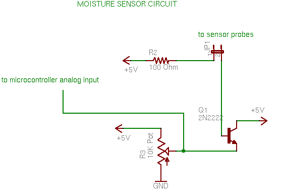 As others have said, building a circuit on Hfe alone is problematic. If you want to consider an opamp google "transimpedance amplifier" which is a simple current-to-voltage topology that's easy to implement (you just need a low input bias current opamp, say pA's, which isn't that hard to find). asdf32 fucked around with this message at 01:46 on Jul 12, 2016 |
|
#
?
Jul 12, 2016 01:42
|
|

|
asdf32 posted:If you want to maximize gain reference the datasheet plots for Hfe. On a quick look I see some transistors are basically flat versus drain current while others increase. For example: I'm pretty sure that's actually the schematic I started with for reference actually, and then it somehow... morphed into the one I have now  quote:As others have said, building a circuit on Hfe alone is problematic. If you want to consider an opamp google "transimpedance amplifier" which is a simple current-to-voltage topology that's easy to implement (you just need a low input bias current opamp, say pA's, which isn't that hard to find). Yeah trying this next, thanks!
|
|
#
?
Jul 12, 2016 02:18
|
|
|
Okay so I let the plant get as dry as I'm comfortable with it getting (they're newly sprouted seedlings and are very sensitive to moisture level right now) and measured a resistance of ~12.5K across the probes, then I poured in water a little at a time and observed a reasonably linear decrease until it bottomed out at about 3K for very water logged, then slowly drifted back up to 3.5K as the excess drained out of the bottom. So I figure my detector should be optimized for the range of ~2.5K to ~15K, just to give it some room to drift due to corrosion or me bumping the probes, etc. I tried one of the op-amp circuits last night but couldn't quite get the feedback right so it would just slam up to one of the rails very quickly past a certain resistance. I think I built it wrong though since it was on a little breadboard and I was tired Thanks again for all the help though
|
|
#
?
Jul 12, 2016 18:18
|
|
|
Try something like this crappy paint.net diagram I made if you have a dual-rail power supply Select R to be as close as possible to the probe's minimum resistance but a bit over, and put a trimpot in series with the probe to calibrate it edit: Vout = -(-5)(R/Rprobe) so it will be low but non-zero when dry and about 5V when wet So with your numbers, for R=3Kohm, Vout=1.2V when dry and Vout=5V when wet BattleMaster fucked around with this message at 20:55 on Jul 12, 2016 |
|
#
?
Jul 12, 2016 20:11
|
|

|
I don't know if anyone saw how many times I edited that last post but when I was working it out on paper I swapped the values of both resistors in the math and it screwed me up very badly! It's correct now though, but non-linear. edit: If you want to make it linear, swap the resistors Fixed version is  and Vout = 5 * (Rprobe/R) so it will be max when dry and min while wet if you select R = max dry resistance BattleMaster fucked around with this message at 21:13 on Jul 12, 2016 |
|
#
?
Jul 12, 2016 20:56
|
|
|
For a bit of fun I sketched up a current source approach with bipolar drive to reduce corrosion: Q1/Q2 and Q3/Q4 form two ~300�A current sources, driving M1 and M2 with a complementary 50% duty cycle square wave (i.e. when one is off, turn on the other one) gives a net zero current through the sensor element (R3). This is basically a H-bridge, but since the top-side is current sources there's no real problem with shoot-through since the current is limited. Output can be sampled on either side of R3, but to avoid having to synchronize the excitation signal with ADC sampling, a half-wave recitifer will buffer the peak voltage. I used two to provide equal loading on both sides of the sensor to reduce the DC component, but only one needs to be sampled. Simulated resistance response at the diode outputs with the values above: 
|
|
#
?
Jul 12, 2016 22:31
|
|
|
longview posted:For a bit of fun I sketched up a current source approach with bipolar drive to reduce corrosion: Wow, that's nice. I didn't even consider corrosion from DC current when I thought about the original problem. Pop that onto a microcontroller with some wifi, add a cute package, some software, and IoT it for money! Make your plants send an angry twitter to you when they need a drink. Sell each sensor for like $30.
|
|
#
?
Jul 13, 2016 02:07
|
|

|
Ok what the hell here is a trans-impedance amp with an AC coupled probe that avoids DC current and runs from a single supply (the AC coupling gives negative voltage for 'free') The driver could be any square wave, including an arduino output. As shown ~5K is half scale. The output corresponds to the ratio of R1/Rprobe (not linear with regards to resistance which may or may not be a downside). 
|
|
#
?
Jul 13, 2016 02:50
|
|
|
longview posted:For a bit of fun I sketched up a current source approach with bipolar drive to reduce corrosion: I like this one because it has the highest part count and therefore must be the best so i'm throwing it together now for funsies  asdf32 posted:Ok what the hell here is a trans-impedance amp with an AC coupled probe that avoids DC current and runs from a single supply (the AC coupling gives negative voltage for 'free') Actually I'll probably try this one too since I still have the ol' op-amp drawer pulled out. I do love it when the thread comes together to over-engineer a problem though 
|
|
#
?
Jul 13, 2016 02:57
|
|
|
For the circuit I drew the Opamp input common mode range needs to include the negative rail. Not all opamps can do that (not even all "rail-to-rail" input opamps can really handle that).
|
|
#
?
Jul 13, 2016 03:17
|
|
|
longview posted:For a bit of fun I sketched up a current source approach with bipolar drive to reduce corrosion: So I put this one together on a breadboard and (after figuring out one of my transistors was blown) it works quite well. The linearity of the real circuit seems to actually only go up to about 8K at which point the voltage seems to asymptotically approach something like 3.4V at open circuit but that's more than enough for what I need it for. Thanks again!
|
|
#
?
Jul 13, 2016 05:42
|
|
|
asdf32 posted:For the circuit I drew the Opamp input common mode range needs to include the negative rail. Not all opamps can do that (not even all "rail-to-rail" input opamps can really handle that). That being said the LM358 could probably work for that circuit, but would probably need more than 5V supply for the best performance. I'm a pretty big hobbyist and outside of a few hi-fi audio and very high frequency opamps all I have laying around in any quantity is NE5532, TL072, TS912 (a pretty decent cheap CMOS opamp for up to 15V supply, rail-rail in/out), and LM8261 which was a recent acquisition for cases where I only need one opamp in my design. Parallel Paraplegic posted:So I put this one together on a breadboard and (after figuring out one of my transistors was blown) it works quite well. The linearity of the real circuit seems to actually only go up to about 8K at which point the voltage seems to asymptotically approach something like 3.4V at open circuit but that's more than enough for what I need it for. Thanks again! The output of the diodes is actually pretty high impedance so any loading on the output will affect the linearity, ideally you'd want a fairly high input impedance opamp to buffer the signal. If you need to change the measurement range just change R1 and R5, larger value gives lower current which means less sensitivity, to really ensure there's no DC you'd also need to match those resistor fairly closely and ensure you have exactly 50% drive on the FETs. My suggestion would be to use a PWM output and drive one side through an inverter (it'll still be a few tens of ns off, but that shouldn't matter). -- The nice thing about the opamp circuit is that it has a resistance response that is well suited for analog meters (most analog resistance meters had a highly non-linear scale with much higher resolution at the lower end of the range, this is easy to forget with modern DMMs). Potential downfall is capacitance to ground at the minus node of the opamp, that's a recipe for oscillation in general (especially if it's an unknown amount that can vary a lot). I can't remember the exact circuit but I designed a circuit like that (minus the AC coupling) for use in a simple test instrument at work that expanded the basic circuit a little and used the opamp as an integrator. In that case there was around 1�F to ground at both the excitation and measurement side of the DUT so it was pretty significant. Since it was driving a panel meter it didn't matter that the output was inverted, since I could just drive the meter differentially relative to a fixed voltage, it even managed around 0.1% accuracy at mid-scale without any calibration when new (I did select the gain set resistor, and use a high quality voltage reference instead of VCC for the reference voltage though).
|
|
#
?
Jul 13, 2016 20:25
|
|
|
longview posted:The output of the diodes is actually pretty high impedance so any loading on the output will affect the linearity, ideally you'd want a fairly high input impedance opamp to buffer the signal. When I was checking it for linearity it was only hooked up to my oscilloscope which afaik should have very high impedance, right? quote:If you need to change the measurement range just change R1 and R5, larger value gives lower current which means less sensitivity, to really ensure there's no DC you'd also need to match those resistor fairly closely and ensure you have exactly 50% drive on the FETs. Already way ahead of you, built it with an inverter in the first place so I can just drive it with one pin / oscillator / whatever. Just for testing and since I am impatient, I'm just writing a high to a pin on the arduino for 5ms then a low for 5ms. I didn't even consider the PWM output until now but that's a much better idea
|
|
#
?
Jul 13, 2016 20:35
|
|
|
Parallel Paraplegic posted:When I was checking it for linearity it was only hooked up to my oscilloscope which afaik should have very high impedance, right? Yeah scopes are usually 10M with the 10x probes or 1M without, in that case it's probably related to the current sources behaving slightly different than the simulation (or the 5V supply is slightly lower than 5V). In fact, it'd probably be a good idea to put around 100k-1M in parallel with the caps to provide a defined discharge path for the capacitors, as is they'll take forever to discharge unless the ADC input loads them down to ground. Good thing about the default Arduino PWM is it's really slow (or at least it used to be), so it should work pretty well for this circuit.
|
|
#
?
Jul 13, 2016 20:52
|
|
|
LM358 used to be my go-to generic op-amp but for low voltage single supply operation I've fallen in love with Microchip's op amps like the MCP6022. edit: the circuit I posted earlier could still be doable with a single-supply rail-to-rail op-amp if the -5V connections were ground and the ground connection on the positive input was 2.5 volts instead, but the output range would be 2.5 volts to 5 volts instead. I don't know about AVRs but with PICs you can set the lower voltage reference to 2.5 volts and then it wouldn't matter. BattleMaster fucked around with this message at 22:34 on Jul 13, 2016 |
|
#
?
Jul 13, 2016 22:22
|
|
|
longview posted:This is why recommending an opamp circuit can be difficult; there's so many different types to consider and most cheap ones that hobbyists are likely to have laying around can't do rail-rail (which you almost always want for those "hey I need some analog in my USB powered Arduino project" questions). Yeah rail-to-rail inputs arn't all that common but are useful. I was annoyed my company library didn't have something to suit a simple 555 circuit a few months back and settled on the LM7301 as my future general purpose choice. Wide supply range (1.8-32V), wide input range (outside both rails), good output swing, SOT-23 package and high availability. We got bit a while back by the OPA140 which has headline supply range down to 4.5V (+/- 2.25) but an input common mode range that can't get within 3.5V of the positive rail which isn't even mid-scale with 4.5V input. That was a bit surprising and had to be re-worked out of a bunch of boards (otherwise it's actually a good all-around amp though). Capacitance on the feedback node can be canceled with a bandwidth limiting integrator cap from out to - which I should have shown.
|
|
#
?
Jul 14, 2016 01:14
|
|
|
I drew up my very first wiring diagram. I THINK it shows what I have wired up. Let me explain. I want to run an elecret mic through two circuits, toggled by an SPDT switch. The first circuit is just the electret running through the trim pot and straight to a mono 1/8 jack. This is a dirty fuzz signal when used on my trumpet. The second circuit will be a gain attenuated signal to hopefully get a clean sound and runs out to the same mono 1/8 jack. What I know is that I need to wire a resistor in series on one side, and parallel on the other, with a ratio of 2:1. The electronics guy at work suggested I start out with 10k and 22k. What I don't know is how to properly wire up the resistor in parallel. I get series. Series is depicted in the schematic below. I don't know where to add the other resistor that would be parallel on the 2nd circuit.  R1 in the image is the trim pot, and R2 would be where the gain attenuation would happen.
|
|
#
?
Jul 14, 2016 03:22
|
|
|
Brekelefuw posted:I drew up my very first wiring diagram. I THINK it shows what I have wired up. Let me explain. This isn't an answer to your question at all but the way your trimpot is hooked up in that diagram it won't actually do any trimming, you have to hook up that arrow bit on the top to one side since that's the wiper (the part that actually slides along and adjusts the resistance). Otherwise it just behaves as a plain old resistor. You can hook it up to either side, the only difference being which way you'd turn the thing to make the volume go up or down.
|
|
#
?
Jul 14, 2016 06:11
|
|
|
Ah OK. Makes sense. In real life the trim pot is hooked up correctly. I have already assembled the first half of the circuit and tested it, which is how I found out it was a dirty fuzz sound.
|
|
#
?
Jul 14, 2016 11:34
|
|
|
Update on the plant water detector: the circuit works well when tested with a 10K pot, but when tested with the actual plant it seems to give impossible readings, as if the plant has negative resistance. Measuring the soil probes shows a small but present voltage across them that I presume is some kind of electrochemical reaction even though the probes are the same metal, and I'm guessing this voltage is enough to gently caress everything up. I went ahead and ordered some graphite rods from amazon that should hopefully work better (and be less toxic to the plant - turns out copper is actually pretty terrible for roots)
|
|
#
?
Jul 18, 2016 17:23
|
|
|
Parallel Paraplegic posted:Update on the plant water detector: the circuit works well when tested with a 10K pot, but when tested with the actual plant it seems to give impossible readings, as if the plant has negative resistance. Measuring the soil probes shows a small but present voltage across them that I presume is some kind of electrochemical reaction even though the probes are the same metal, and I'm guessing this voltage is enough to gently caress everything up. LOL. Yeah, there's going to be some odd electrochemistry going on in an actual plant. The copper will kill everything (that's why they use it in boat bottom paint, and copper nails will kill a tree). You know that there are plant moisture sensors commercially available, right?
|
|
#
?
Jul 18, 2016 18:06
|
|


|
sharkytm posted:You know that there are plant moisture sensors commercially available, right? Yeah well I can also just go and buy the vegetables already grown too but that takes all the fun out of it
|
|
#
?
Jul 18, 2016 21:16
|
|
|
So I've been poking around taobao for adjustable power supplies, and came across this:  It looked a lot more skookum than most of the other cheap power supplies I've seen (costs around $45 usd assembled, including the aluminum case), and after some digging, it appears to be a hobby/enthusiast project. I just wanted to share because I've been noticing a bunch of these "humblefacture" sort of projects where it's just some guy putting something he designed on the market, made possible by affordable prototyping/short run manufacturing. The emphasis is often on the price:performance ratio rather than cheapest price, so a lot of the other projects (open source high frequency soldering irons, standalone CNC controller) really appeal to me, and are a step up from usual cheap Chinese crap.   (This is priced at ~$60) rawrr fucked around with this message at 03:59 on Jul 19, 2016 |
|
#
?
Jul 19, 2016 03:57
|
|

|
rawrr posted:So I've been poking around taobao for adjustable power supplies, and came across this: This is pretty cool, you should post more of it since my Chinese level is barely elementary and I don't know what to search for.
|
|
#
?
Jul 20, 2016 06:14
|
|
|
meatpotato posted:This is pretty cool, you should post more of it since my Chinese level is barely elementary and I don't know what to search for. The power supply on top is just an industrial constant voltage / constant current module I bought off ebay for like $30, in a box with a transformer. It works reasonably well but is pretty janky and I wouldn't trust it for anything but short tests. I'll link the module when I get home. Anyway I was doing some more research and apparently the "best" way to measure soil moisture is using time-domain reflectometry, I wonder if I could build that myself 
|
|
#
?
Jul 21, 2016 16:08
|
|
|
It's not "industrial"; it's designed for hobbyist use. The module itself is about $20 from the designer (https://item.taobao.com/item.htm?id=533100084987&_u=l2bv29q3b9ba), and you can buy it off eBay/Aliexpress through resellers. The enclosure is designed and sold by someone else that just designs enclosures - here's one he made for the raspberry pi out of CNC aluminum for around $13: and a ridiculously overbuilt battery charging fixture  Can you tell me more about the jankyness? I haven't bought it yet because it doesn't seem like the UI/control scheme is particularly well thought out (compared to having separate knobs to adjust voltage and current). meatpotato posted:This is pretty cool, you should post more of it since my Chinese level is barely elementary and I don't know what to search for. In general just search for <keyword> and some permutation of 套件 (kit), "DIY", or �白菜�. You still have to wade through a bunch of cheap crap though, the nicer stuff is the exception rather than the norm. e: actually �白菜� ("cabbage") might refer only to the soldering iron stuff that takes Hakko handle/tips. rawrr fucked around with this message at 18:45 on Jul 21, 2016 |
|
#
?
Jul 21, 2016 17:16
|
|
|
Well it was sold to me as an industrial panel power supply unit so that's where I got that idea. As for jankyness, yeah the UI is pretty bad, and while it works fine for low power levels the minute you try pulling more than a few watts through it (not like 100, more like 10-20) its voltage dips a bit and then it suddenly reboots. This was just running it through a power resistor within its rated range for voltage and current. It seems to work okay with less than one amp and less than like 10-20V as far as I can tell; I still use it for testing out LED's and stuff sometimes when my bench power supply would be inconvenient for one reason or another.
|
|
#
?
Jul 21, 2016 18:04
|
|
|
Parallel Paraplegic posted:Well it was sold to me as an industrial panel power supply unit so that's where I got that idea. How are you supplying power to it? If voltage is dipping the just sounds like a problem with the power supply as opposed to the module, since it seems like it's essentially just some sort of step down converter. I was able to dig up a few english reviews (the rest are in Russian) and they seem to like it: https://www.youtube.com/watch?v=Jp8lBjgYOp0 https://www.youtube.com/watch?v=W5gjrq_9t_s And I like that the designer collects them in his own youtube playlist and comments in the reviews "glen liu 3 weeks ago Hi friend I like your video and you add a case on the DP50V2A. in face this device name is DP50V2A. I guss you want to ask why, because i am the designer of this power supply module .. your case is very good and there are heat dissipation holes. it is very smart. � Anyway it's weird that I'm shilling for it without really even wanting to buy one yet, but I just really dig the fact that it seems more like an enthusiast project that clearly has some thought and passion behind it, rather than the run of the mill Chinese crap that's built down to a price.
|
|
#
?
Jul 21, 2016 18:17
|
|
|
Gotta ask: what does cabbage have to do with electronics?
|
|
#
?
Jul 21, 2016 18:45
|
|
|
I THINK it's just a play on the word "Hakko" which means white light, and cabbage transliterates to "white veggies", indicating that it's a cheaper/ghetto version of the real thing. I was reading up on it and the upgraded version of "cabbage" is "beef" - "because beef is obviously more delicious than cabbage". This is the handle for "beef": 
|
|
#
?
Jul 21, 2016 18:59
|
|
|
Parallel Paraplegic posted:Anyway I was doing some more research and apparently the "best" way to measure soil moisture is using time-domain reflectometry, I wonder if I could build that myself Definitely let us know how well that goes! I have some cheapo sensors on the way from china now as well. There are some decent commercial ones available for around 40 bucks but that's definitely not as fun and also more expensive than a lifetime supply of herbs that I'd watering with this setup  E: typos mobby_6kl fucked around with this message at 14:50 on Jul 22, 2016 |
|
#
?
Jul 22, 2016 13:47
|
|

|
mobby_6kl posted:Definitely let us know how well that goes! Well I looked into it and I don't think I'd be able to make anything useful. Some grad student seems to have done a thesis on using an FPGA to make a cheap TDR sensor for this application, but studying it a bit more it seems much more appropriate for measuring soil levels along large areas (like under a whole field or down a borehole) since it's basically RADAR going over a waveguide. If I wanted to do it over a short distance like my tiny potted plant I'd need sampling equipment operating up in the gigahertz range just to be able to differentiate the transmit and receive due to the round trip time being so short. Anyway my soil measurement project has turned into a full-on autogarden project that I've sketched up designs for. Part of it is switching on and off the growing light, and I remember this thread warning me off of building something that switches AC voltages while being unattended because if something goes wrong the insurance adjuster would have a field day with my hand-assembled not-UL-listed thing. I remembered I had a dinky old remote control switch I got at walgreens for like $5 so I pulled apart the remote and studied it a bit the other day. Looks like it's an incredibly simple design, just a 433MHz crystal being turned off and on by an IC. Hooked up the logic analyzer and got the signals the IC sends (which are encoded pretty weird, more on that in a second). Then I noticed on amazon that you can buy cheapo 433MHz modules, so I got one of those and fed in the captured signal and it worked great. Here's a capture of the "packet" it sends, anyone know what kind of encoding this is? At first I thought it was Manchester but that doesn't make sense. As far as I can tell each "bit" is a constant width, and there's two symbols - a "long" for a 1 and a "short" for a 0. Under that assumption I was able to write code that output correct packets from an arduino, but I'm still curious as to what the name of this kind of code is - some kind of pulse width modulation maybe?  I decoded this packet as "11001100010110001000100000"
|
|
#
?
Jul 22, 2016 14:44
|
|
|
Wait I'm dumb it's not "some kind of" pulse width modulation it literally is pulse width modulation
|
|
#
?
Jul 22, 2016 14:48
|
|
|

|
| # ? Jun 5, 2024 00:03 |
|
|
Parallel Paraplegic posted:
I've seen self-clocked 1-wire protocols like this, but it wasn't given a name that implied it was standardized. The weird thing is, the one I saw (adafruit's neopixels) was heavily time sensitive, so it wasn't PWM per se; it was strict duration after the rising edge. If I'm remembering it right, anyway. In any case, it would match your decoding.
|
|
#
?
Jul 22, 2016 14:53
|
|


