|
I like to use http://www.makercase.com and a laser cutter. If you don't have access to a laser cutter I highly recommend joining a makerspace that does.
|
 #
?
Jan 20, 2018 17:15
#
?
Jan 20, 2018 17:15
|
|


|

|
| # ? May 30, 2024 09:31 |
|
|
Sagebrush posted:Yes. That code will read all the addresses from 0 to 32767, print out the contents in ASCII and hex, and then lock up at the end, as the comment indicates: So what's the best way to go about getting it to set that to false? I mean, the for/while is supposed to be while less than 32768? Is that proper addressing for a 256k Parallel EPROM?
|
|
#
?
Jan 20, 2018 17:41
|
|


|
CommieGIR posted:So what's the best way to go about getting it to set that to false? I mean, the for/while is supposed to be while less than 32768? If I'm understanding correctly, you could make a couple additions like the following: void setup() { ... bool done = false; } void loop() { ... while (!done) { for (addr = 0; addr < 32768; addr += 16) { ... } } done = true; } The loop will still run forever, but it'll stop executing the for loop once it gets through it once and your done flag is set.
|
|
#
?
Jan 20, 2018 18:00
|
|


|
Sir Bobert Fishbone posted:If I'm understanding correctly, you could make a couple additions like the following: Awesome, yeah I'm aware that by design the loop itself never ends, I just needed a way to 'terminate' the main portion of the loop so I get a single read through. That should work, thanks! Just FYI: Arduino wants the Boolean declares prior to void setup() apparently, as it threw an out of scope error until I placed it above setup. CommieGIR fucked around with this message at 18:20 on Jan 20, 2018 |
|
#
?
Jan 20, 2018 18:08
|
|
|
Couldn't you just run it in the setup block and leave the loop empty?
|
|
#
?
Jan 20, 2018 18:21
|
|


|
Collateral Damage posted:Couldn't you just run it in the setup block and leave the loop empty? You generally want to avoid that, and there's certain constraints that will not get set or read inside the setup() block that need to be set in order to cycle through all the blocks. I mean, you can totally do that, but it might break some types of loops/arguments. CommieGIR fucked around with this message at 18:34 on Jan 20, 2018 |
|
#
?
Jan 20, 2018 18:23
|
|
|
CommieGIR posted:Awesome, yeah I'm aware that by design the loop itself never ends, I just needed a way to 'terminate' the main portion of the loop so I get a single read through. Dur, I'm not smart. Good catch.
|
|
#
?
Jan 20, 2018 18:41
|
|
|
Sir Bobert Fishbone posted:Dur, I'm not smart. Good catch. So, new interesting issue, it never stopped running, so to debug I added a print for the addr variable. So, once it hits 32768, it goes -32768 and counts BACKWARDS to zero again, then starts again. code:EDIT: I may know why, it might be an 8 bit versus 16 bit issue. Testing a theory. \/\/\/\/ Yup, that's the issue. CommieGIR fucked around with this message at 19:32 on Jan 20, 2018 |
|
#
?
Jan 20, 2018 19:22
|
|
|
That's because addr is a signed int. The highest-order bit is used to indicate positive or negative sign, so once that bit flips to 1, it renders as -32768, and add operations move it back toward zero. You could declare it as an unsigned int and then it would go from 32767 to 0.
|
|
#
?
Jan 20, 2018 19:24
|
|


|
Data Graham posted:That's because addr is a signed int. The highest-order bit is used to indicate positive or negative sign, so once that bit flips to 1, it renders as -32768, and add operations move it back toward zero. Oh, crap. But then it would still never trigger the done because it would need to exceed the addr < to exit the loop. EDIT Nope, it worked! Do I need to set the total addr 16 higher to catch the final 32768 address block? Also nope, confirmed that just results in addr 0 being read again. Woohoo! Confirmed the image is a Z80 compatible image, which is the CPU that reads these ROMs.! CommieGIR fucked around with this message at 20:21 on Jan 20, 2018 |
|
#
?
Jan 20, 2018 19:28
|
|
|
I added support for 64k with simple uncommenting, I'd like to add a Serial menu to handle this later, but for now its tested and works perfectly!code:
|
|
#
?
Jan 20, 2018 22:28
|
|
|
you can try using preprocessor directives in the future, instead of manually commenting bits outcode:There are a lot of other ways of doing this with various pros and cons -- I like the preprocessor method but there are good reasons to try other strategies.
|
|
#
?
Jan 20, 2018 22:35
|
|


|
Sagebrush posted:you can try using preprocessor directives in the future, instead of manually commenting bits out That's what I was looking for, thank you so much! Yeah, I'm not a fan of manually commenting the code, but I have limited C/C++ experience. EDIT: I made a couple changes: code:CommieGIR fucked around with this message at 23:24 on Jan 20, 2018 |
|
#
?
Jan 20, 2018 22:37
|
|
|
Splode posted:Nice work! Take a photo, I'm always interested in how people approach one-off enclosures (as it's the part where all my projects turn to poo poo) I made a project for work that tests six batteries at a time. It tests how long it takes to go from a full charge to 6.7VDC. Step 0: Standby/Charge Step 1: Drain the battery to 6.7VDC and display the voltage on the LCD Step 2: Charge the battery for 4 hours and display a countdown timer. Step 3: Drain the battery to 6.7VDC and display a countup timer and voltage. Step 4: If drain time > 4 hours, display "Pass"(Time) and recharge the battery. Step 5: If drain time < 4 hours, display "Fail"(Time) and recharge the battery. I used a fire extinguisher enclosure for the case. It is made out of some kind of hard rear end steel that was a pain to cut and drill. I had a friend with a laser cutter make a template for the screw holes, button holes, and LCD cutouts. Two of the batteries have shorted out causing the relay and some of the traces on the breadboard to fry, so the upper right red 12VDC distribution block is getting replaced by a fuse block when we get a slow day at work. As a bonus, all the machining on the case has to be done in my basement since we don't have the tools at work, so I get to "work from home" when working on the enclosure. 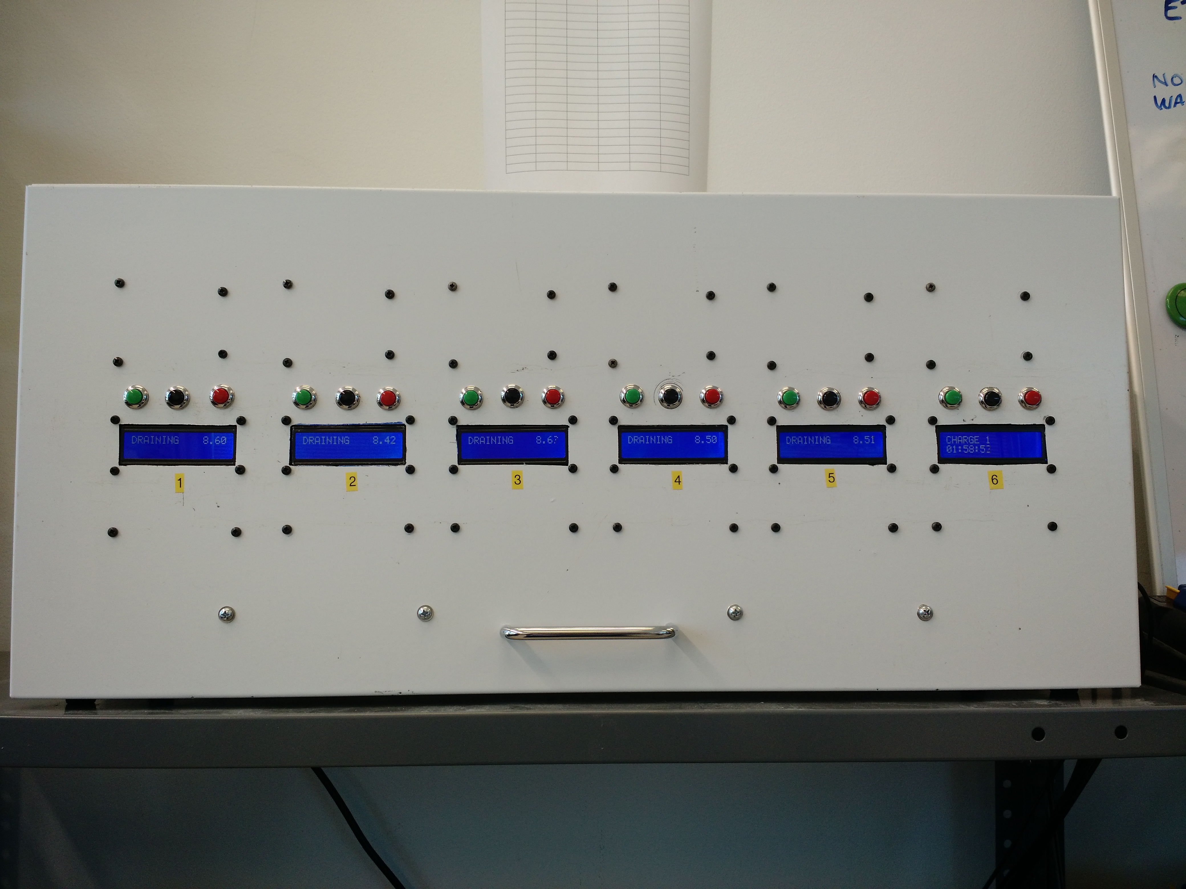 
|
|
#
?
Jan 21, 2018 13:31
|
|


|
That is a lot of Arduinos! May I recommend you replace the breadboards with veroboard or some other more permanent solution? Looks great though.
|
|
#
?
Jan 21, 2018 21:00
|
|

|
Splode posted:That is a lot of Arduinos! May I recommend you replace the breadboards with veroboard or some other more permanent solution? Looks great though. Those are adafruit permaprotos, regular perfboard laid out like a standard breadboard. They�re great and pretty much all I ever use.
|
|
#
?
Jan 21, 2018 22:00
|
|


|
Sockser posted:Those are adafruit permaprotos, regular perfboard laid out like a standard breadboard. They’re great and pretty much all I ever use. Ahh fair enough, I've never seen them before
|
|
#
?
Jan 21, 2018 22:04
|
|
|
e: nevermind
|
|
#
?
Jan 21, 2018 22:23
|
|


|
Splode posted:Ahh fair enough, I've never seen them before That was my fault for calling them breadboards in my post. Sockser is right that they are Adafruit permaproto boards and they are indeed great.
|
|
#
?
Jan 21, 2018 22:36
|
|
|
I am pondering buying some RC-style servos for general robot building. I have built stuff using steppers, BLDC and DC-brushed motors, but have not ever used RC-type servos before (either for a robot or for RC toys). One thing that I am sure of is that I want the ones that have multiple mounting points for metal brackets all over them, not the plain RC kind. I also want some continuous-rotation servos that are the same way. The Robogeek ones would cost around $35 each, for one example. They have both a 180 and a 360 model. $35 or so is about as much as I'd care to spend. https://www.robotgeek.com/rg-180-servo I have read of the fancy Dynamixel servos, but think they'd cost too much. I'd be okay with just plain PWM servos, as opposed to smart servos or the serial/pass-through ones. Are there any others like this? Made specifically for robot use? I also may buy some of the tiny cheapo blue ones, just because they only cost a couple bucks each from China-land. They are only like $10 for 5. ....... I buy lots of electronics supplies on aliexpress, but can't find many good choices for bigger RC servos on there. There is places that sell quarter-scale servos, but all of them only want to ship them some way that has no tracking. Or a way that has tracking, but costs a lot... They won't send them e-packet or USPS first class. The only way that you can get tracking is to send them a more-expensive method like Fedex-IE or DHL, that costs $25+ just to ship one servo.
|
|
#
?
Jan 22, 2018 13:52
|
|
|
Hobbyking.com has a small selection of robotics servos, and a large selection of general servos. You can always replace the servo arms with a multi-hole plate you mentioned. Here's a slightly better servo than the robotgeek one you linked: https://hobbyking.com/en_us/turnigytm-tgy-s901d-ds-mg-robot-servo-13kg-0-14sec-58g.html
|
|
#
?
Jan 22, 2018 18:32
|
|
|
I don't know how many times I have to learn the same lesson, but its almost always a bad ground causing pretty much every problem.
|
|
#
?
Jan 23, 2018 15:29
|
|

|
porksmash posted:Hobbyking.com has a small selection of robotics servos, and a large selection of general servos. You can always replace the servo arms with a multi-hole plate you mentioned. Here's a slightly better servo than the robotgeek one you linked: https://hobbyking.com/en_us/turnigytm-tgy-s901d-ds-mg-robot-servo-13kg-0-14sec-58g.html Normal servos just have the screw brackets at both ends, because that works fine for holding them down in normal RC-vehicle use. With robots often the servo bearings end up being the joint for the load, so the double-C-brackets work a lot better. Maybe there is something I don't know about here however... MOST of the "robotic" servos that Hobby King seems to show have the normal-RC-style mounting? The Robostar one appears to have some small mounting holes, but they don't show any brackets for it? https://hobbyking.com/en_us/robostar-srs-3216htg-280-digital-metal-gear-high-voltage-robot-servo-32-4kg-0-16sec-73g.html And the Turnigy one has no apparent mounting method at all? How do you attach the servo body to (anything)? https://hobbyking.com/en_us/turnigytm-tgy-s902-robotic-bb-ds-mg-servo-13kg-0-14sec-58g.html
|
|
#
?
Jan 23, 2018 16:17
|
|
|
The smooth body ones are usually press-fit into a servo shaped hole and glued (or just straight up glued onto a flat area) into place on R/C models. The amount of load they bear is much lower than the situation you described. Sorry those didn't work out.
|
|
#
?
Jan 23, 2018 18:05
|
|
|
Data Graham posted:That's because addr is a signed int. The highest-order bit is used to indicate positive or negative sign, so once that bit flips to 1, it renders as -32768, and add operations move it back toward zero. Uhhhh...not quite. We live in a twos complement world (for integers), not sign-magnitude. And if it were an unsigned 16 bit int, it would go from 65535 to 0.
|
|
#
?
Jan 26, 2018 12:12
|
|

|
feedmegin posted:Uhhhh...not quite. We live in a twos complement world (for integers), not sign-magnitude. And if it were an unsigned 16 bit int, it would go from 65535 to 0. Well, setting them to unsigned int fixed the issue at least.
|
|
#
?
Jan 26, 2018 17:37
|
|
|
feedmegin posted:Uhhhh...not quite. We live in a twos complement world (for integers), not sign-magnitude. And if it were an unsigned 16 bit int, it would go from 65535 to 0. Huh. Good to know that distinction, thanks. Interesting exercise to see how they differ.
|
|
#
?
Jan 26, 2018 18:23
|
|
|
Has anyone else worked with the USB mouse emulator library? A few months ago, I wrote some code for my M0 Pro to do some basic mouse commands on my laptop (running Windows 10), and it worked perfectly. Yesterday, I tried plugging the same M0 pro into the same laptop and running the same code, but the laptop isn't recognizing mouse commands from the board. I tried plugging the board into my Surface Pro 3 (also running Windows 10), and that worked. What gives?
|
|
#
?
Jan 28, 2018 22:20
|
|
|
I haven't used an M0 specifically but that sounds like your laptop is loading the wrong drivers or something. Look in device manager or run a USB probe tool and see what's happening when you plug it in and it enumerates?
|
|
#
?
Jan 28, 2018 23:45
|
|
|
Sagebrush posted:I haven't used an M0 specifically but that sounds like your laptop is loading the wrong drivers or something. Look in device manager or run a USB probe tool and see what's happening when you plug it in and it enumerates? On the Surface Pro 3, it appears as "HID-compliant mouse" under "Mice". On my laptop and desktop, it appears under "Ports" as "Arduino M0 PRO Native Port". Any idea how to fix that?
|
|
#
?
Jan 29, 2018 05:16
|
|
|
I couldn't get either the mouse or keyboard libraries to work when I used platform io to compile, but they worked fine with the Arduino IDE. I skimread somewhere that there was some issue fixed in 1.6.6 of the arduino IDE that fixed something related to this?
|
|
#
?
Jan 29, 2018 12:08
|
|
|
I just uninstalled the Arduino software and drivers from my laptop, and now it recognizes the board as a mouse. I could've sworn I had previously tested the mouse functions on my desktop - something must have happened with either a newer version of the Arduino software of a recent Windows update.
|
|
#
?
Jan 31, 2018 03:07
|
|
|
Does anyone know of an arduino or teensy or similar carrier board that has some isolated IO?
|
|
#
?
Feb 8, 2018 19:22
|
|


|
taqueso posted:Does anyone know of an arduino or teensy or similar carrier board that has some isolated IO? Not off the top of my head, (I checked and the ruggeduino isn't isolated), but you'll probably have more luck finding an external module or shield.
|
|
#
?
Feb 9, 2018 11:36
|
|
|
Isolated like optoisolated? If so, https://www.sparkfun.com/products/9118 If not, what do you mean?
|
|
#
?
Feb 9, 2018 14:14
|
|

|
Opto or digital isolators, these are slow signals so opto will work fine. I was hoping for a carrier with say 6in/6out channels and screw terminals. I think I am going to go ahead and roll my own board for this since I couldn't find what I was looking for and the customer likes the idea of having their logo on the board and seems willing to pay for some extra NRE. Thanks for looking, I appreciate it.
|
|
#
?
Feb 9, 2018 23:31
|
|
|
Has someone seen something like a ESP8266 with a battery backed RTC? Is that a thing? I saw a $50 Arduino IOT type device but I was hoping for something smaller / cheaper.
|
|
#
?
Mar 21, 2018 19:07
|
|

|
I used the esp8266 to pull time from time servers rather than use an RTC, but that might not be viable for whatever you're doing. I haven't seen any boards with both an esp8266 and rtc though. you'll probably need to design your own or live with seperate modules.
|
|
#
?
Mar 22, 2018 14:52
|
|
|
It'll be a separate module, but they're not that hard to find, even in 3.3V.
|
|
#
?
Mar 23, 2018 11:16
|
|

|

|
| # ? May 30, 2024 09:31 |
|
|
ultrabay2000 posted:Has someone seen something like a ESP8266 with a battery backed RTC? Is that a thing?
|
|
#
?
Mar 23, 2018 11:44
|
|