


|
Mr. Glass posted:this isn't really what you asked for, but if you're willing to ditch the cut tape entirely i recently got some of these for organizing my smt stuff: https://www.amazon.com/gp/product/B0787166LX/ Yeah I already have a few of those, though I've only used them for organizing loose stuff since I get the feeling the second I start taking SMD caps out of the strips I'm going to get them all mixed up
|
 #
?
Mar 5, 2018 03:24
#
?
Mar 5, 2018 03:24
|
|


|

|
| # ? Jun 4, 2024 10:54 |
|
|
Anyone here worked with Carbon Nanotube Gas Sensors? The NASA stuff: https://www.nasa.gov/ames-partnerships/technology/chemical-nanosensor Thanks.
|
|
#
?
Mar 7, 2018 00:07
|
|

|
My cat somehow peed on some electronic components  Most of them were still in their Mouser zip-loc bags but a few were loose, any recommendations on cleaning them? I assume just isopropyl + dry thoroughly?
|
|
#
?
Mar 12, 2018 17:27
|
|
|
ate all the Oreos posted:My cat somehow peed on some electronic components Flux remover, 99% iso, deionized water x2, then dry?
|
|
#
?
Mar 12, 2018 20:35
|
|


|
How long has it been? If the cat pee didn't dry up, a wash with tap water (and dish soap if you want) should get the nasty off and won't hurt anything*. A rinse with deionized or distilled water will make sure you don't leave mineral deposits. If it's all dried up and old, it might be corroded and will at least be gross. Depending on what ICs they were I would just chuck them rather than deal with it. *Some things like speakers have bits that you don't want to get wet. And some things like switches have cavities that can be a bitch to get the water out of. Alcohol/flux remover won't hurt, but I don't think you need them.
|
|
#
?
Mar 12, 2018 20:47
|
|


|
taqueso posted:How long has it been? If the cat pee didn't dry up, a wash with tap water (and dish soap if you want) should get the nasty off and won't hurt anything*. A rinse with deionized or distilled water will make sure you don't leave mineral deposits. If it's all dried up and old, it might be corroded and will at least be gross. Depending on what ICs they were I would just chuck them rather than deal with it. He did it sometime last night or this morning, so I don't think anything's corroded yet. It was a very recent order that I hadn't sorted yet so I don't want to just throw it away  I'm pretty sure these things are all water-safe so I guess I'll just give that a try, thanks.
|
|
#
?
Mar 12, 2018 21:18
|
|
|
Two unrelated questions from separate projects: Q1. What microcontroller board or accessory would be the easiest to make a bluetooth keyboard? The ESP32 has bluetooth, but using it to act as a keyboard seems to be fairly shaky (lots of "git pull the latest to survive"). I want to make a little 3-key device that can send Media Prev/Next/PlayPause to my phone in the car. Q2. What hardware+library combo makes it easiest to make an interface with screen plus a few buttons? I've done it from scratch before, but a friend of mine is making a project and doesn't have as much software experience, so I'd like to be able to suggest a cheap LCD that would allow him to wire up a few buttons and code in terms of "when button is pressed go to this menu and do this thing" instead of "in the event loop check the button voltage and update state variables accordingly". The platform is something Arduino-flavored.
|
|
#
?
Mar 15, 2018 02:50
|
|

|
Stabby McDamage posted:Two unrelated questions from separate projects: A1: Adafruit's Bluefruit LE Micro might be your easiest option. It's an Atmega32u4 with BLE, and, IIRC, it's Arduino IDE supported out of the box. A2: That's almost certainly the Arduino LCD KeyPad shield, which I think is made by several companies. I haven't tried that particular board, but it's popular enough that there should be an out-of-the-box library for it.
|
|
#
?
Mar 15, 2018 04:14
|
|
|
Stabby McDamage posted:Two unrelated questions from separate projects: My aquarium has a built-in fluorescent lighting solution like like this one that does not turn on, no flickering or anything at all. I tried taking each of the tubes out but it made no difference. 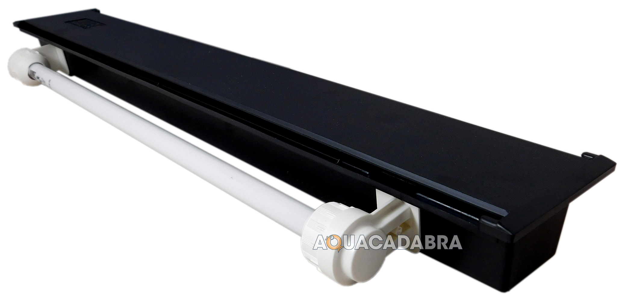 This is a pretty expensive bastard to replace so I'd like to try to diagnose this further, is there anything I can do with just a multimeter? The ballast is probably sealed inside the black box part but I might be able to get to it with some effort.
|
|
#
?
Mar 15, 2018 11:37
|
|

|
Be warned, the lcd with buttons module that's most common uses a single analogue pin and some resistor silliness for all the buttons. This is a nightmare to debounce and not idiot proof. It might actually be simpler to just buy a screen module seperately to some buttons. As for menus and poo poo, I don't think there is anything like that for micros library wise. U8glib is the best library I've ever used for lcds but it's not high level enough to do menus for you.
|
|
#
?
Mar 15, 2018 11:53
|
|

|
poeticoddity posted:A1: Adafruit's Bluefruit LE Micro might be your easiest option. It's an Atmega32u4 with BLE, and, IIRC, it's Arduino IDE supported out of the box. On the BLE thing: Looks good, but I'm stupidly disappointed that it just seems to be an Adafruit thing and not a made-in-china-by-the-bucketload thing. It does look like an easy bet...I'm just spoiled on $4 parts. On the KeyPad shield, that looks perfect, ordering a bunch now. mobby_6kl posted:I know this is the DIY forum but I feel like this will be a ton of effort for what you can already get for a few bucks from ebay that will look and probably work better. I actually have one of that exact thing, but the issues are (a) it goes to sleep and requires a keypress+wait to come back online and reconnect and (b) the form factor doesn't have good tactile feedback to use without looking. If I make one that's powered by the car power, it will power+connect on car start (just like the vehicle bluetooth audio) and run as long as the car is on without a sleep state. Saying that now, I wonder if I could just hack apart one of those buttons to craft it to more ergonomic buttons and junction it to car power, but it would still go to sleep on long drives. mobby_6kl posted:My aquarium has a built-in fluorescent lighting solution like like this one that does not turn on, no flickering or anything at all. I tried taking each of the tubes out but it made no difference. I'm not a fish expert, but could you just replace it with LED strip? That's what I did with an old LCD monitor with a flourescent backlight -- high density LED strip brought it back to life. Not sure if fish need special wavelengths or something. Splode posted:Be warned, the lcd with buttons module that's most common uses a single analogue pin and some resistor silliness for all the buttons. This is a nightmare to debounce and not idiot proof. It might actually be simpler to just buy a screen module seperately to some buttons. Thanks for the heads up. I'll probably just check the button status with 10 iterations of averaging just to solve it the lazy way.
|
|
#
?
Mar 16, 2018 04:45
|
|
|
Stabby McDamage posted:On the BLE thing: Looks good, but I'm stupidly disappointed that it just seems to be an Adafruit thing and not a made-in-china-by-the-bucketload thing. It does look like an easy bet...I'm just spoiled on $4 parts. Stabby McDamage posted:I actually have one of that exact thing, but the issues are (a) it goes to sleep and requires a keypress+wait to come back online and reconnect and (b) the form factor doesn't have good tactile feedback to use without looking. If I make one that's powered by the car power, it will power+connect on car start (just like the vehicle bluetooth audio) and run as long as the car is on without a sleep state. Saying that now, I wonder if I could just hack apart one of those buttons to craft it to more ergonomic buttons and junction it to car power, but it would still go to sleep on long drives. Stabby McDamage posted:I'm not a fish expert, but could you just replace it with LED strip? That's what I did with an old LCD monitor with a flourescent backlight -- high density LED strip brought it back to life. Not sure if fish need special wavelengths or something.
|
|
#
?
Mar 16, 2018 14:49
|
|
|
mobby_6kl posted:I don't have any plants and fish don't care, it's just to make them look all pretty. I have a bunch of LED strips but they're not really powerful enough, the tank now has two 50W tubes so a 18W strip isn't going to come close. They make more dense lights specifically for this purpose so that's the backup solution. I switched to LED over my tanks years ago and I will never ever go back to fluorescents. Buy once, last forever! From your description of the problem I'd blame the ballast. That's almost always the second thing to kick it on a fluorescent aquarium fixture, the first being the bulbs. If you plug it in and turn it on and listen carefully, can you hear anything from the sealed area?
|
|
#
?
Mar 18, 2018 17:48
|
|

|
I've been playing with royer oscillators lately because I have a bunch of tiny low-power CCFL transformers and it's fun to make high voltage regulated power supplies. I found this app note that's full of neat designs for very stable high voltage regulators and am using that as a jumping-off point: http://cds.linear.com/docs/en/application-note/AN118fb.pdf I already had one of my designs made by allpcb and it works great, but I noticed something I kinda overlooked: The capacitors that form the tank circuit with the transformer need to be able to withstand high currents. Right now I'm just using dinky ceramics which do get worryingly warm when it's left running for more than a minute or two, so before I do version 2 of this power supply I'd like to figure out the right components to use. To try to get some idea of what I need, I built the circuit in LTSpice and the simulations are telling me the capacitors experience peaks upwards of 2A and an RMS of 250mA, which is currently split across two caps. From what I understand, the thing I'm looking for is the ripple current rating right? Octopart is pretty unhelpful (barely anything even has ripple current specified, and the only things that do are all polarized tantalums), is there just some rule of thumb I should follow like "capacitors of type X can withstand a lot of current?" Would picking a low-ESR capacitor be a good place to start, since I presume the ESR is what's actually causing the current to turn into heat?
|
|
#
?
Mar 20, 2018 21:42
|
|
|
Film caps are usually characterized for RMS voltage over frequency, which is basically the same thing. You'll notice the first design in the app note specifies Wima MKS caps, which are metallized polyester. I've never been able to find good specifications for ceramic cap current derating, the specified dissipation factor is usually low enough that you don't end up with a lot of power for most applications though.
|
|
#
?
Mar 20, 2018 22:19
|
|


|
longview posted:Film caps are usually characterized for RMS voltage over frequency, which is basically the same thing. Thanks! longview posted:I've never been able to find good specifications for ceramic cap current derating, the specified dissipation factor is usually low enough that you don't end up with a lot of power for most applications though. The closest I found was Murata saying something like "just buy a few and run them at the current you want and see if they increase in temperature less than 20C over ambient" which is super helpful thanks guys 
|
|
#
?
Mar 20, 2018 23:48
|
|
|
ate all the Oreos posted:The closest I found was Murata saying something like "just buy a few and run them at the current you want and see if they increase in temperature less than 20C over ambient" which is super helpful thanks guys If that's the level of detail we're operating on then I can say from practical testing that running 10A peak at 150kHz in a 100nF 1206 cap will make it hot enough to melt solder after about 30 seconds.
|
|
#
?
Mar 20, 2018 23:59
|
|
|
I just scrolled all the way down to the bottom of that app note for the first time  Thanks for the insight into your depressing life Jim  longview posted:If that's the level of detail we're operating on then I can say from practical testing that running 10A peak at 150kHz in a 100nF 1206 cap will make it hot enough to melt solder after about 30 seconds. Yeah generally I rate parts on a scale of "normal" -> "warm" -> "uncomfortably hot" -> "made a sizzling sound when I touched it" -> "instant burn" -> "desoldered itself" -> "on fire" -> "vaporized" so that fits perfect
|
|
#
?
Mar 21, 2018 00:43
|
|
|
ate all the Oreos posted:Thanks for the insight into your depressing life Jim He said he had a great time!
|
|
#
?
Mar 21, 2018 00:49
|
|
|
I kind of want to pick up a benchtop power supply for random junk, any good ones?
|
|
#
?
Mar 27, 2018 21:02
|
|


|
shovelbum posted:I kind of want to pick up a benchtop power supply for random junk, any good ones? If you're just going to be screwing around with stuff and don't need it to be super reliable or perfect I'd say just go on ebay and look for lightly used ones, I got a pretty nice one that normally retails for like $150 for something like $70 because some kid at the nearby college bought it to use for all of two classes before deciding to switch majors and I happened to be on ebay at the right time 
|
|
#
?
Mar 27, 2018 21:26
|
|
|
Hi Megathread. A dumb question about something I know just enough to get myself in trouble about and am getting more confused by googling: Recently picked up an old Zenith tube radio that powers on but does not actually send anything to the speaker, and frankly, I don't want to try and fix a 70 year old tube radio that a)needs 70 year old tubes and b) has innards that look like someone spilled a radio shack in them, so I'm planning to put some 12v DC bluetooth guts in it and use it as a very cool speaker. But this gets me into doing two things that I need information on: 1) It has a totally awesome pinky-tip sized glow tube to show that it's on and (really poorly) illuminate the dial. I really want to keep this, but the voltage at the tube is 50v AC, so somewhere between the 110v in and the glow tube (in a mess of tubes, transformers, radio bits, etc), 60 volts are being eaten. I can't step down 60 volts AC with resistors without burning my house down, correct? I want to keep as little of the radio chassis live as I can, so I'd love to find a way to power this off the household current, but that will require some kind of stepdown transformer, right? Or, can I run 6v DC to it? I have no idea how tubes react to DC, but I'm going to imagine poorly. Which leads me to my next question 2) I'd LOVE to use its existing on/volume pot as the on switch for the new electronics, and just disconnect everything after that, run the power from there to a DC adapter, and run the bluetooth and amp boards off of that (so wall->on/volume pot->glow tube(?)->12v DC adapter->new high-tech boards), but do old volume pots like that give a consistent 110v out off one of the pins once it clicks on, or is the entire voltage affected? The pot itself is the next thing in line after the plug, so the main power for the radio goes through it before splitting off into many places. I can't find a way (yet) to see if any of its 5 pins are sending full voltage or not because I'm having a hard time completing a circuit with what I can get to safely with my multimeter probes to get a reading. I figured I would ask before I do anything destructive/heroic. Are there any ersatz-pots out there are are just on/off? Am I going to cook my 12v DC stuff if I just crank the volume pot all the way up every time I turn it on to get full voltage to the DC adapter? Edit: In case anyone is interested, its this radio: https://www.radiomuseum.org/r/zenith_g724_ch7g02.html Edit to edit, realized I phrased the start of 2) poorly. stealie72 fucked around with this message at 16:23 on Mar 30, 2018 |
|
#
?
Mar 30, 2018 16:10
|
|
|
stealie72 posted:Hi Megathread. A dumb question about something I know just enough to get myself in trouble about and am getting more confused by googling: This is probably a neon indicator lamp, which actually usually are just hooked directly to mains with a (relatively high-value) series resistor. They require only a teeny tiny bit of current, so you can use a resistor large enough that even dropping 60V across it won't even make it get warm. If you're not comfortable working with mains voltage though I'd probably just replace it with an LED powered off the low-voltage, since otherwise you'd need to step the DC voltage back up to like 90V just to turn the neon indicator on. stealie72 posted:Which leads me to my next question I haven't ever seen a radio that controlled the volume by adjusting the entire input voltage using a pot like that before, if you're right about how it works that's... kinda scary? Like I'm not even sure how you'd get that to work without it loving up the receiver a bunch and going out of tune... Anyway you probably don't want to use it inline with the DC adapter though, because the DC adapter will automatically increase current in response to sagging voltage to keep the power running through it constant. More current = more heat = more melty bits, possibly. You sure you can't just remove the knob from the pot and put it on a modern pot (with integrated switch, if that's what you're going for)?
|
|
#
?
Mar 30, 2018 18:38
|
|
|
Oh I misread you, you're asking if the whole voltage is affected. No, generally the clicky bit that's actually doing the switching is a totally separate thing from the potentiometer / volume control, and they're just built into the same component, so you should be able to find which wires go to which part and work from there.
|
|
#
?
Mar 30, 2018 18:46
|
|
|
ate all the Oreos posted:This is probably a neon indicator lamp, which actually usually are just hooked directly to mains with a (relatively high-value) series resistor. They require only a teeny tiny bit of current, so you can use a resistor large enough that even dropping 60V across it won't even make it get warm. I just found this bit on Wiki: "In 1930s radio sets, neon lamps were used as tuning indicators, called "tuneons" and would give a brighter glow as the station was tuned in correctly" and I'm wondering if mine is somehow hooked up this way and since the radio bits aren't working, it's just showing a consistent 50v draw. ate all the Oreos posted:Oh I misread you, you're asking if the whole voltage is affected. No, generally the clicky bit that's actually doing the switching is a totally separate thing from the potentiometer / volume control, and they're just built into the same component, so you should be able to find which wires go to which part and work from there.
|
|
#
?
Mar 30, 2018 19:18
|
|
|
stealie72 posted:Looking up pictures, that's exactly what it is, and it draws little enough at 50v that it's just grounded to the chassis. Any idea what resistor I would need to knock 60v off for something like that? I've been trying to look up calculators online and they've not been helpful for a mostly layman. Are you probing around while it's powered up? If you're actually measuring it dropping 50V or whatever then there's probably already a resistor in series with it somewhere, and if that's the case I'd just use that one (or at least check it to see what value it is). Neon indicators are a bit tricky because they exhibit something called negative resistance - when the voltage across them reaches about 90V, they strike (start glowing) and conduct as much current as it takes to drop the voltage across them down to ~50-60V (which it sounds like is what you're measuring). So the resistor in series isn't actually determining the voltage - the neon does that because it will always try to conduct as much current as required to keep the voltage right at ~50-60V - it's just limiting the current so that the neon doesn't try to conduct "infinity" current. So what you're trying to calculate isn't "What resistor value will give 60V" but "what resistor value will, when the ~60V [left over after the neon subtracts its ~60V] is applied across it, result in the correct current?" If I remember correctly neons generally operate on a little less than 1mA. 100K to 220K would be good places to start, though if you can deal with the neon being a little dim I'd go for the higher-value since overdriving the thing will cause it to slowly blacken over time, but underdriving it will mean it'll last essentially forever. stealie72 posted:I just found this bit on Wiki: "In 1930s radio sets, neon lamps were used as tuning indicators, called "tuneons" and would give a brighter glow as the station was tuned in correctly" and I'm wondering if mine is somehow hooked up this way and since the radio bits aren't working, it's just showing a consistent 50v draw. If it's hooked up like that I think it would just not light at all. Generally when they're used to show tuning it's obvious that that's what they're used for - the case would have some silkscreen saying "tuning indicator" or something like that. e: I just went ahead and tried a 100K resistor with a neon from my parts bin and it seems to be glowing nicely without being overdriven, so I'd say go ahead and use that with it. Shame Boy fucked around with this message at 19:58 on Mar 30, 2018 |
|
#
?
Mar 30, 2018 19:50
|
|
|
Got it. Thank you for the lesson and for the quickie experiment for me!!
|
|
#
?
Mar 30, 2018 20:48
|
|
|
Hey guys, making a simple chime/alarm for my home Home Assistant installation using a nodeMCU and a small amp and speaker. I've done several nodemcu sensor projects already but this is my first time working with audio at all. Everything works great, except for that when it's sitting idle there's a low volume static/popping that comes from the speaker. It happens even with the data pin disconnected (I'm not using a DAC since I'm just playing PWM tones). I'm using these cheapo amplifiers. I'm assuming this is a power filtering issue? My knowledge here is extremely limited but I'm hoping this is solvable by placing an appropriately sized capacitor somewhere but I'm not sure exactly sure where/how. Can anyone help me out?  e: at least one amazon reviewer says they're just noisy pieces of poo poo, in which case, can anyone recommend an equivalent one that sucks less? ee: oh jeez, even just hooking this thing up to a 5v supply with the only the speaker connected and nothing else I get AM radio though it. To clarify I am not looking for hi fidelity audio, all I want is to play basic chime / alarm sounds at a volume louder than a Piezo buzzer and be silent otherwise. Are there some super loud Piezos out there because that would be the simplest solution for me. CheddarGoblin fucked around with this message at 01:18 on Apr 1, 2018 |
|
#
?
Mar 31, 2018 23:40
|
|
|
n.. posted:...Everything works great, except for that when it's sitting idle there's a low volume static/popping that comes from the speaker.,,, What you can try is to connect a 10K pot across the amp's input & ground, adjust the pot to it to its max resistance and then try turning the pot resistance down to see if it doesn't help. The lower the pot resistance, the lower the amp's output will be--but the idea is that it reduces the amp's own noise more than the signal noise. Also try some RF/conductive & grounded shielding for the whole thing.... Note: Do not ground the speaker wires at all... Speaker wires are normally a floating voltage; a speaker's ground connection is not the same ground as everything else. You never attach a speaker wire 'ground' to the common electrical 'ground' unless the technical info for that amp/IC says you can do that. Each speaker's two wires is their own little circuit for just the two of them. You do not connect them to anything else, or even each other (no common ground) unless you know that the amp/circuit allows that. edmund745 fucked around with this message at 12:50 on Apr 1, 2018 |
|
#
?
Apr 1, 2018 12:43
|
|
|
n.. posted:Hey guys, making a simple chime/alarm for my home Home Assistant installation using a nodeMCU and a small amp and speaker. I've done several nodemcu sensor projects already but this is my first time working with audio at all.
|
|
#
?
Apr 1, 2018 20:53
|
|

|
n.. posted:Hey guys, making a simple chime/alarm for my home Home Assistant installation using a nodeMCU and a small amp and speaker. I've done several nodemcu sensor projects already but this is my first time working with audio at all. Does that board have two pins for ground? It�s hard to tell from the amazon pic but based on your hookup that�s what it looks like. If one of the pins is an audio ground you can try disconnecting it. Try dropping a cap across your + and - power on the bread board to smooth out any noise from the power supply. This should help the hiss when there is no signal present. Unfortunately there will probably always be some kind of low level hiss, even in some of the big professional PA systems with balanced outputs I get a bit of hiss if you get close to the speaker, all you can do is minimize it by having good gain structure; you want the output level from the micro controller to be as high as possible without clipping/distortion so that when it hits the amp, you�re using as little of the gain on the amp as possible to get the volume you need. This will minimize the noise floor being amplified. Also consider how far away you will be from the speaker when it is installed in the final position; if it is going to be ceiling mounted you might never have a listening position closer than 3�, and the hiss might not be as noticeable at that distance as it is sitting on the table in front of you. If you�re still getting AM radio interference, you should try enclosing the amp and wiring (which is acting as an antenna) in a metal box and connect the enclosure to one of those ground pins on the amp or the - power rail. Lastly, if none of the above help, you could build a low-pass filter that sits on the lines between the amp and speaker. Most of the hiss is going to be at 8k hz and above, and your chime sounds most likely fall in the lower frequencies between 500 and 4k hz so you won�t lose much. This can be done with a passive RC circuit; 1K ohm resistor between the amp�s + and the speaker�s +, and a 0.02 uF cap from the speaker�s + to the speaker�s-. edit- here's a diagram for the lowpass filter: 
ickna fucked around with this message at 21:38 on Apr 1, 2018 |
|
#
?
Apr 1, 2018 21:18
|
|

|
Thanks for the responses everyone. Yes the little amp board does in fact have two ground inputs, one being for power and one for the audio. I disconnect the audio one and it didn't make a difference. Also I realized the AM radio I was hearing was because I was holding it while it was powered up - if I give it power and don't touch it (or hook up the nodemcu) the hiss is really quiet and low enough to not be an issue (you really have to have your ear right up to it). It's really just the popping noises it makes when the nodemcu is running that's the most annoying, I'll try the cap across the power + and - and see if it helps.Parts Kit posted:Out of curiosity, have you tried powering the amp off of the 3v3 pin instead of VIN? The amp is advertised for 5-12v, would that be safe? I have read that the 3.3 output is a lot less noisy. ickna posted:Also consider how far away you will be from the speaker when it is installed in the final position; if it is going to be ceiling mounted you might never have a listening position closer than 3�, and the hiss might not be as noticeable at that distance as it is sitting on the table in front of you. There will probably be 2-3 of them around the house at power outlet level. I'm going to make some plug-in 3d printed enclosures for them like I did for my multisensors: 
CheddarGoblin fucked around with this message at 22:04 on Apr 1, 2018 |
|
#
?
Apr 1, 2018 21:55
|
|
|
Separate postin' my own NodeMCU project from last night: I built this little guy to show me the sensor values for temp and humidity inside my apartment and out on the porch. The sensors are SI7021 breakouts on their own NodeMCU boards dumping data into OpenHAB with MQTT. They're flashed with the Sonoff-Tasmota firmware because I have a bunch of those modules and I love having the web interface to configure and troubleshoot them without having to reflash the firmware. I had to write my own firmware for the display, which was a great learning experience. My favorite feature is the PWM control of the backlight over MQTT, because I can tie it in to all my other OpenHAB scripts. It's nice to have the display dim accordingly when I switch scenes or turn off when I go to bed. Now that it's working, I need to solder up a small board for the PWM transistor and trim pot, then design an enclosure for it to be 3D printed.
|
|
#
?
Apr 1, 2018 21:58
|
|
|
n.. posted:The amp is advertised for 5-12v, would that be safe? I have read that the 3.3 output is a lot less noisy. And speaking of these sorts of circuits, I've run into something that has a non-adjustable but too hot analog audio output for recording. Am I right in assuming that if I want to make a rudimentary volume control I would just use a pot between the signal out pin and ground pin of that connector, with the desired output on the wiper? I'm assuming that would give me a little voltage divider circuit that I could use to dial in something more reasonable. Maybe add in a fixed resistor on the connection to ground so it can't short too?
|
|
#
?
Apr 2, 2018 12:06
|
|
|
That'd work. There's no real reason to add the ground resistor. The amp will see the full potentiometer resistance even when the wiper is at 0, and it can be nice to have a volume control that goes all the way to 0. It's also more common to put the volume control potentiometer on the input, as then you're not putting the full power of the amplifier though the potentiometer. If it's a low power amplifier, or would require invasive modifications you may not wish to bother. Lastly, look for a logarithmic/audio taper pot. They're better for audio because ears have a roughly exponential response.
|
|
#
?
Apr 2, 2018 16:52
|
|

|
Thank you. Fortunately this is a line level output so the pot shouldn�t have to dissipate much.
|
|
#
?
Apr 2, 2018 18:34
|
|
|
Looks like I came in at a good time for pot discussion.  I've got a switch/volume pot out of a set of active speakers I need to replace, but I'm not familiar with pot markings. It's marked B503, and my quick internet research suggests that indicates it's a linear 50K, correct? TerminalSaint fucked around with this message at 09:10 on Apr 3, 2018 |
|
#
?
Apr 3, 2018 04:42
|
|


|
TerminalSaint posted:Looks like I came in at a good time for pot discussion. Yup. I'm guessing since it is a linear pot it is probably for setting the gain for whatever IC or transistor in the circuit that is actually doing the work, instead of a log pot which would be used for attenuating the output directly.
|
|
#
?
Apr 3, 2018 07:06
|
|
|
Cool, thanks. Now for the real fun of tracking one down.
|
|
#
?
Apr 3, 2018 09:26
|
|
|

|
| # ? Jun 4, 2024 10:54 |
|
|
Does anyone have any interest in the tube set from this radio? https://www.radiomuseum.org/r/zenith_g724_ch7g02.html No idea if any of them work, but if any of you have a tube collection, just PM me your address and they're yours. I will feel bad if I just toss them.
|
|
#
?
Apr 4, 2018 19:35
|
|