|
Is the relay closing long/well enough for you to see the lights? Like what happens in this circuit if you just wire the relay coil right up to 9V or whatever. Troubleshoot it systematically from the trouble spot back to the source, imo. You know the LEDs are good so manually close the relay and see if they are getting enough juice, if it's good when you do that you will need to look at the driver circuit.
|
 #
?
Oct 19, 2018 21:44
#
?
Oct 19, 2018 21:44
|
|


|

|
| # ? May 28, 2024 02:46 |
|
|
Sagebrush posted:I'm starting to see a lot of these three-color e-ink displays showing up on the usual parts sites: I have one sitting around. I never really bothered to use it when I realized that it has a refresh time of like 30 seconds. I think they only make sense for a standalone device that very rarely updates.
|
|
#
?
Oct 19, 2018 22:48
|
|


|
Spazzle posted:I have one sitting around. I never really bothered to use it when I realized that it has a refresh time of like 30 seconds. I think they only make sense for a standalone device that very rarely updates. I mean the huge benefit is they use zero power when they're not updating, so yeah they're great for something like a clock that only changes once a minute or something like that. I had a flash drive a long time ago that had a strip of e-ink display stuff built in that would update to show a bar graph of how full the drive was when you unmounted it, so without even plugging it in you could tell if it had space on it or not, it was pretty clever.
|
|
#
?
Oct 19, 2018 23:02
|
|


|
Radio du Cambodge posted:I'm working on what I thought would be a simple project and keep running into stumbling blocks. Basically I'm trying to make a circuit that lights up a bunch of LEDs when triggered by an audio input, specifically a synthesized kickdrum. Like an LED strobe but light tied to an audio pulse instead of a steady beat. Let's start with the LED board! The bright green parts have copper under them. The dull green is where the copper's been etched away. So if you follow the bright green parts, all the LEDs are wired in parallel. Following it back down to around the wires, one side goes across the resistor, then into where the wires attach on the left (assuming the wire bends around and comes into that solder blob from the back side). The other side of the LEDs goes down under that middle of the knoby thing and into that solder blob. Is the solder blob where the wire on the right attaches? (What's the knob do? Do you turn it to make the light brighter/dimmer or is it an on/off switch?) The resistor has "2R0" written on it, which means it should be a 2.0 ohm resistor. Supposing the LEDs have a forward voltage drop of about 2.5V (typical for a white LED), applying 9V would do: 9V in, 2.5V drop over LED, the rest drops over the resistor. So V(across resistor) = 6.5V V(across resistor) = I(through resistor) * R(of resistor): 6.5V = I * 2ohms => I=3.25A=magic smoke So that's not what's actually happening. What does the back of it look like and where do the wires actually attach? On to the control parts:  This is what you have? When it's idle, the drum signal is holding steady with some offset relative to everything else. When you hit it, it oscillates some around that steady state value. The signal is weak and can't source very much current. The wire goes into C1, which passes only the high-frequency parts of it. The DC part is blocked, so the other side will be at 0V when the drum isn't sounding and oscillate above/below 0V when it is. The signal is still weak. Then it goes into RV1. This is the first thing that seems wrong to me. As you turn the pot knob, the resistance between the audio signal and ground goes down. It's lowering the amplitude of the audio signal by drawing current out of the pickup. This would typically be connected like this:  where the pickup is driving into a constant load and the amplifier input is on a resistor divider. Then the oscillating signal goes into the amplifier. The amplifier does this: Output = Input * 20 + (half VCC) The output can also source/sink more current before it distorts. For 0V input, it outputs a 4.5V output. For a -100mV input, it outputs 2.5V. For a 100mV input, it outputs 6.5V So now we have an oscillating signal with bigger amplitude that can drive current and is centered around 4.5V C2 doesn't do anything particularly interesting (changes the frequency response some) C3 is similar to C0 and blocks the DC part of the signal. So the output heading to the relay is oscillating around 0V instead. Overall Example: A signal from the drum oscillating between -80mV and 120mV would be output as a signal oscillating between -2V and 2V. It'll be oscillating at audio frequencies (10-20kHZ) The relay isn't going to be particularly happy with that. You're effectively trying to open and close the relay hundreds-to-thousands of time per second. Also, a relay isn't a good choice for that switch in general since you'll only get about ~100000 cycles out of cheap one. What do you want the output to look like? On for as long as the amplitude from the drum is above a threshold? Foxfire_ fucked around with this message at 06:43 on Oct 20, 2018 |
|
#
?
Oct 20, 2018 05:48
|
|


|
peepsalot posted:Is each array rated at 9V? You can't wire them all in series and expect to power them from the same voltage. There is a typical voltage drop of roughly 3.5V across white LEDs (your arrays appear to be 24 LED all in parallel, but putting the arrays in series multiplies that voltage drop), When you tested the LEDs "wired straight up to a 9V supply ", was this already with them wired in series, and was it the same 9V 1A supply? Thanks for the tips! No, the LED worklights I took them out of are each powered by 2 or 3 little 1.5V batteries. I'm not sure how I did it before but I just tested my set-up just hooking up all the LED arrays to my 9V supply and it is the same dimness (the LED board closest to the power supply is brightest, each board dimmer than the last). So hooking the LED arrays in parallel would help?My power supply is probably still too weak. I think the relay I'm using has a current draw of 42mA if I'm reading the spec sheet correctly. You're right, I wrote that incorrectly. It should be 2 ohms as the poster below pointed out (I measured more like 6 ohms with a multimeter and tested the circuit with 10ohms previously so I got mixed up) and on the LED side. shovelbum posted:Is the relay closing long/well enough for you to see the lights? Like what happens in this circuit if you just wire the relay coil right up to 9V or whatever. Yeah good call, I wanted to see if I was missing anything really obvious before step-by-step troubleshooting because I was afraid I'd need to de-solder a bunch of work but this is the best way to proceed. Foxfire_ posted:Following it back down to around the wires, one side goes across the resistor, then into where the wires attach on the left (assuming the wire bends around and comes into that solder blob from the back side). The other side of the LEDs goes down under that middle of the knoby thing and into that solder blob. Is the solder blob where the wire on the right attaches? (What's the knob do? Do you turn it to make the light brighter/dimmer or is it an on/off switch?)  quote:The resistor has "2R0" written on it, which means it should be a 2.0 ohm resistor. quote:On to the control parts: Thanks for this detailed analysis, exactly the stuff that I have difficulty with. Yep that's the circuit I have. I was basically cobbling together bits of audio circuits I've built in the past. quote:Overall Example:  As you say, the relays are cheap and in future versions I'll put it in a socket instead of directly soldered to the board so I can switch it out if it gets exhausted. EDIT: Another option I'll play around with is seeing if I can send a trigger/gate output from my sampler directly instead of a kickdrum, to avoid the rapid open-close clacking of the relay caused by audio frequency AC. Between that and re-soldering all my LED boards in parallel maybe it'll be good enough for this show, then I can look into a more advanced circuit for the future! Wait, would doing the LED arrays in parallel, in other words attaching the 9V supply to the small resistors on each board before they go through the LEDs, reduce the overall resistance [1/r = 1/(r+r+r+r)] and fry my stuff? Should I add a 10ohm resistor at the end like I accidentally did in my original schematic? Or am I misunderstanding something. 
Radio du Cambodge fucked around with this message at 17:24 on Oct 20, 2018 |
|
#
?
Oct 20, 2018 15:54
|
|

|
Don't put 9v across your LEDs that were designed for 3v power, it will destroy them. Either power them from 3v, add another current limiting resistor sized for 9v input, or put 3 modules in series so each one gets about a 3v drop (this is a bad solution, they will be uneven brightness or possibly damaged depending on variation in the LEDs) For fixing the control, one easy way would be to run the post amplifier signal into a comparator, run that into a oneshot, and then use that to switch power to the LEDs with a mosfet
|
|
#
?
Oct 21, 2018 00:04
|
|
|
Foxfire_ posted:Don't put 9v across your LEDs that were designed for 3v power, it will destroy them. Series leds is good. They have the same current going though them, and thus are as even as they can be. Parallel leds alone can cause uneven brightness and current sharing. If each parallel led segment has a resistor though, the resistor will dominate over the thermal effects and mismatching of the bare led and pretty much takes care of that problem. Radio du Cambodge posted:Wait, would doing the LED arrays in parallel, in other words attaching the 9V supply to the small resistors on each board before they go through the LEDs, reduce the overall resistance [1/r = 1/(r+r+r+r)] and fry my stuff? Should I add a 10ohm resistor at the end like I accidentally did in my original schematic? Or am I misunderstanding something. Paralleling those led sets will reduce the overall resistance, the individual ones will still be at whatever resistance they are at, you're just stressing the power supply more. If you're upping the voltage you'll need another resistor. While you can do it the way you've drawn, with one after all of the segments in parallel, I'd recommend one per led segment. This will share the power. 10ohms at 666ma is about 4 watts of power dissipated. You could get a single large enough resistor, or you could place individual smaller resistors on the individual segments. Please note that you're still going to be talking about 4 watts either way, it's just slightly easier to deal with distributed. It's also easier to figure out what value you need. With a single resistor, the value you need will change depending on how many segments you use, and it's not exactly trivial to figure out. Placing it on the individual segments it'll be easy to figure out. If you series 2 (or more) of your led segments and increase their effective forward voltage you'll cut down how much power your dissipating as heat.
|
|
#
?
Oct 21, 2018 01:15
|
|

|
You could probably rectify and filter the trigger signal and then run it through a comparator to get the pulse you want.
|
|
#
?
Oct 21, 2018 04:30
|
|


|
Thanks for all your guys' help, really appreciated! Since I'm under a bit of time pressure I decided to just go a really redundant and wasteful route: I bought a couple more relays and some battery connectors and put each LED array (4 total) on a separate battery. To avoid any possible complications from using 9V, I dropped the voltage in the LED circuits to 5V (I checked and the LED boards are meant to run on 4.5V) with some voltage regulators. Audio amp still on the 9V power supply. For the trigger, I just created a little synthetic trigger pulse as an audio file and had it play simultaneously with my kick drum out of a separate audio jack into my original amplification circuit (although I did change the potentiometer wiring as per your recommendation foxfire). It seems to be a bit gentler than the kick drum trigger, not as much clacking, so hopefully my relays will not give up the ghost while I'm playing. Yall are probably going to laugh at my schematic but it works, check the video below :P  https://www.youtube.com/watch?v=AS01o2ftwzE When I have some more time I'll look into cleaning up the trigger pulse because I can tell it's inefficient. Try some comparator circuits.
|
|
#
?
Oct 22, 2018 02:14
|
|
|
Radio du Cambodge posted:When I have some more time I'll look into cleaning up the trigger pulse because I can tell it's inefficient. Try some comparator circuits. Am I confused, or is this the perfect signal for a 555 in one-shot mode? A crazy series of pulses show up, the 555 latches on the first one for time X, then can't be re-triggered for time Y.
|
|
#
?
Oct 24, 2018 00:14
|
|


|
For a drum that would probably work okay. It depends on what you want to have happen on sustained notes (that a drum can't really play). If you plugged it into a guitar and played a chord, what should happen: - One flash of light at the start of the chord, then off: Use a nonretriggerable oneshot (like a 555) - LED on at 100% as until the volume drops below some level: Use a retriggerable oneshot - LED intensity proportional to volume: Use an envelope follower circuit to filter the amplifier output, eliminate the relay/mosfet, and drive the LEDs with a big beefy buffer amp
|
|
#
?
Oct 24, 2018 04:21
|
|
|
Would it be outrageous to try and build a trackball from scratch? All the information I can find is from people gutting mice and slapping big balls on them. I don't have to control every electron. If there are off-the-shelf parts that do the heavy lifting, that's fine. I'm not worried about practicality. I'm just interested in the project as a learning experience, and a way to frustrate myself but not sexually.
|
|
#
?
Oct 24, 2018 23:02
|
|

|
Veni Vidi Ameche! posted:Would it be outrageous to try and build a trackball from scratch? All the information I can find is from people gutting mice and slapping big balls on them. I don't have to control every electron. If there are off-the-shelf parts that do the heavy lifting, that's fine. I'm not worried about practicality. I'm just interested in the project as a learning experience, and a way to frustrate myself but not sexually. If you're not worried about it not working very well any project is a good learning experience.
|
|
#
?
Oct 24, 2018 23:35
|
|

|
The first functional computer trackball was a five-pin bowling ball rolling on bearings with optical encoders pushed up against it in two axes. I know this because it was invented in Canada and so every Canadian kid learns about it as part of the grade school science "Canada used to have a tech industry too, you know, eh" unit   If you can build the mechanical design to make the ball spin smoothly, the slotwheel electronics are actually relatively simple. Probably won't be as accurate or responsive as an optical one but hey, who cares, it looks like a fun project.
|
|
#
?
Oct 25, 2018 03:55
|
|


|
Veni Vidi Ameche! posted:Would it be outrageous to try and build a trackball from scratch? All the information I can find is from people gutting mice and slapping big balls on them. I don't have to control every electron. If there are off-the-shelf parts that do the heavy lifting, that's fine. I'm not worried about practicality. I'm just interested in the project as a learning experience, and a way to frustrate myself but not sexually. If you want to build an HID from scratch, regardless of the input mechanism, you may want to look into some of the non-Uno/non-Mega Arduino boards that can act as an HID on their own. The build for this would have to be a bit different than normal trackballs, but it'd be pretty nifty if you made a trackball that had sensors to detect when it was being twisted rather than rolled and spit that out either as scroll wheel activity or keystrokes. I just looked into it and there's a Katamari game supposedly coming to PC later this year, so "big-rear end scroll wheel with spin detection" could make for a pretty awesome controller for that.
|
|
#
?
Oct 25, 2018 04:41
|
|
|
As someone who got like, a few steps into designing a trackball device before giving up and ripping apart an existing trackball to harvest the relative bits out of, yeah the mechanical parts are by far the hardest to figure out. The actual electronics are just a controller that interprets two rotary encoders that indicate X and Y movement. If I were you I'd start with just a dev board (arduino or whatever) and two rotary encoders - the standard knob ones you can get everywhere. Get the software working with that basic hardware so that one knob is X, the other is Y, and you can twiddle them and make your mouse move around. Then all you have to do is the "easy" part of building a trackball holder and mounting more appropriate rotary encoders and wheels and stuff 
|
|
#
?
Oct 25, 2018 04:44
|
|
|
Splode posted:If you're not worried about it not working very well any project is a good learning experience. Sure, and I�m not worried about it being the greatest trackball in the world. I don�t know if there are like ten off-the-shelf pieces that every junior-high whiz-kid knows you can use to build a trackball, or if I need to start stringing together shift registers. I did some research, but all I could find were people cannibalizing mice. I want to do a bit more than that. Sagebrush posted:The first functional computer trackball was a five-pin bowling ball rolling on bearings with optical encoders pushed up against it in two axes. I know this because it was invented in Canada and so every Canadian kid learns about it as part of the grade school science "Canada used to have a tech industry too, you know, eh" unit This owns. I want to do something like this. I have about a hundred microcontrollers of many flavors lying around. I could �cheat� by using those for signal processing. In fact, I have a thousand of just about every small electronic part, because I always go way overboard when I take up new hobbies. I don�t think I have any optical encoders, though. I do have regular rotary encoders. I�d like to look into what other options are suitable for this, anyway. I�ll also need to figure out what to send out over USB to identify the device, and to send usable signals. I�ve never interfaced any of my projects with a computer. poeticoddity posted:If you want to build an HID from scratch, regardless of the input mechanism, you may want to look into some of the non-Uno/non-Mega Arduino boards that can act as an HID on their own. Is that a thing? Arduino has microcontrollers specifically for this type of application? I�m not kidding when I say I�ve got just about every type or Arduino and Arduino knockoff I could find, but I don�t remember buying any with that in mind. I�ll have a look. I gotta say, the twist idea sounds really cool. I am sure this entire thing is beyond me, and I�ll fail completely, but twisting is on the list, as of now. Shame Boy posted:As someone who got like, a few steps into designing a trackball device before giving up and ripping apart an existing trackball to harvest the relative bits out of, yeah the mechanical parts are by far the hardest to figure out. The actual electronics are just a controller that interprets two rotary encoders that indicate X and Y movement. If I were you I'd start with just a dev board (arduino or whatever) and two rotary encoders - the standard knob ones you can get everywhere. Get the software working with that basic hardware so that one knob is X, the other is Y, and you can twiddle them and make your mouse move around. Then all you have to do is the "easy" part of building a trackball holder and mounting more appropriate rotary encoders and wheels and stuff Your message is a mixed blessing. On the one hand, I�m bummed that you gave up on this, because that doesn�t bode well for me. On the other hand, you present a stripped-down version of the idea that I feel like I can get working, pending my ability to build a proper frame for the ball.
|
|
#
?
Oct 25, 2018 04:53
|
|
|
Veni Vidi Ameche! posted:Is that a thing? Arduino has microcontrollers specifically for this type of application? I�m not kidding when I say I�ve got just about every type or Arduino and Arduino knockoff I could find, but I don�t remember buying any with that in mind. I�ll have a look. https://www.arduino.cc/en/Reference/HID It requires a board with a 32u4 chip, but I've got one running in some lab equipment I built and it's been really solid.
|
|
#
?
Oct 25, 2018 05:07
|
|
|
Veni Vidi Ameche! posted:Is that a thing? Arduino has microcontrollers specifically for this type of application? I�m not kidding when I say I�ve got just about every type or Arduino and Arduino knockoff I could find, but I don�t remember buying any with that in mind. I�ll have a look. Any Arduino or knockoff that uses an ATMega32U4 can natively behave as a HID. Off the top of my head, that's the Arduino Leonardo, the Arduino Pro Micro, or the Teensy 2.0. They all talk directly to your computer with an internal USB stack, so they can emulate all kinds of devices. The Arduinos that use 328Ps can't do that* because the USB port is connected to a USB-to-serial converter, not directly to the processor. *modern UNOs can technically be programmed to emulate HIDs but it involves reflashing the mega16u2 that's doing the serial translation so it is definitely not recommended to non-experts. Just pick up some pro micros from amazon
|
|
#
?
Oct 25, 2018 05:09
|
|
|
babyeatingpsychopath posted:Am I confused, or is this the perfect signal for a 555 in one-shot mode? A crazy series of pulses show up, the 555 latches on the first one for time X, then can't be re-triggered for time Y. Yeah makes sense. Honestly I did not even look into a 555-based circuit because I really dislike soldering at this point in my life and was trying to get the lowest number of parts possible. But that would probably be easier than twiddling with op-amps, in the long run.
|
|
#
?
Oct 25, 2018 05:29
|
|
|
Shame Boy posted:the mechanical parts are by far the hardest to figure out I'm pretty adept with electronics and designing/making/assembling electronic things but the above seems to hold true for any project I attempt
|
|
#
?
Oct 25, 2018 09:38
|
|

|
poeticoddity posted:https://www.arduino.cc/en/Reference/HID Sagebrush posted:Any Arduino or knockoff that uses an ATMega32U4 can natively behave as a HID. Off the top of my head, that's the Arduino Leonardo, the Arduino Pro Micro, or the Teensy 2.0. They all talk directly to your computer with an internal USB stack, so they can emulate all kinds of devices. Oh, cool. I have several boards based on the 32U4. They're probably all massive overkill for this, but at least I have them on hand.
|
|
#
?
Oct 25, 2018 14:53
|
|
|
If you are interested in trying to build your own optical rotary encoders, there is a german youtuber with a few videos on the subject that are pretty good intros to how they work: https://www.youtube.com/watch?v=VSDQzrUMeuM https://www.youtube.com/watch?v=dPBKTZw_xi4
|
|
#
?
Oct 25, 2018 17:30
|
|


|
(Cross posting from the IYG stereo thread after waiting a few days. Any thoughts anyone? I'd like to make a fun repair project if this is at all doable) I have a stereo receiver that is making a horrible buzz. It's an 80s Sony STR-AV200 that I use for a phonograph, radio, and mp3 player. It's worked fine for years. Speaker impedance is definitely matched. Stereo hasn't always been grounded (it only has a 2 prong plug), but connecting the chassis ground screw to a ground doesn't help the buzz. The problem: The left speaker channel developed a buzz. This happened fairly suddenly. It plays no matter what mode is on. The buzz is of constant volume regardless of any adjustment of volume or balance, and always on the left. Turning the stereo off and back on sometimes clears the buzz for a while, but that's working less and less. The buzz usually fades in within about 5 seconds. The most recent time, the left speaker initially made a weird unsteady staticy noise, which faded out as the buzz faded in. I confirmed it's not the speaker itself by switching L/R speakers, and the buzz moved to the right speaker (now plugged into the left terminal) - so it's definitely the channel or terminal. The buzz originally developed in speaker terminal set B (I didn't use terminal set A and they were turned off). When I switched the speakers both to speaker terminals A, the buzz was gone for a while. But a few days later it developed again. The way it fades in after about 5 seconds makes me think something capacitor related? Idk. I'm decent at messing with circuits and I have a mild hobbyist level of electronics tools but I don't know how to troubleshoot a stereo. Any ideas? Is there a better thread for this?
|
|
#
?
Oct 25, 2018 22:32
|
|


|
alnilam posted:(Cross posting from the IYG stereo thread after waiting a few days. Any thoughts anyone? I'd like to make a fun repair project if this is at all doable) An easy thing to verify would be to just pop the lid off and take a look at the circuit board. Make sure none of the capacitors look suspicious (bulged, leaking, etc.) and also look to see if there's any like, gunk on the board. There's some weird silicone-y goop some vendors previously used to glue stuff in place and keep it from vibrating, that after a few years apparently breaks down and becomes conductive. As far as I know the only kind of goop that does this is black colored, so if you see any black gunk use a multimeter to see if it's conductive at all. What's the buzz like, does it sound like a mains hum (like the noise a microwave makes) or something else?
|
|
#
?
Oct 25, 2018 23:04
|
|
|
Replaced some capacitors on this board for my welder, there's till another board that has got some more capacitors of this type on it. Got the components back in june but never got around to it. First time desoldering components, the backside doesn't look so clean, how do you get rid of the black crud?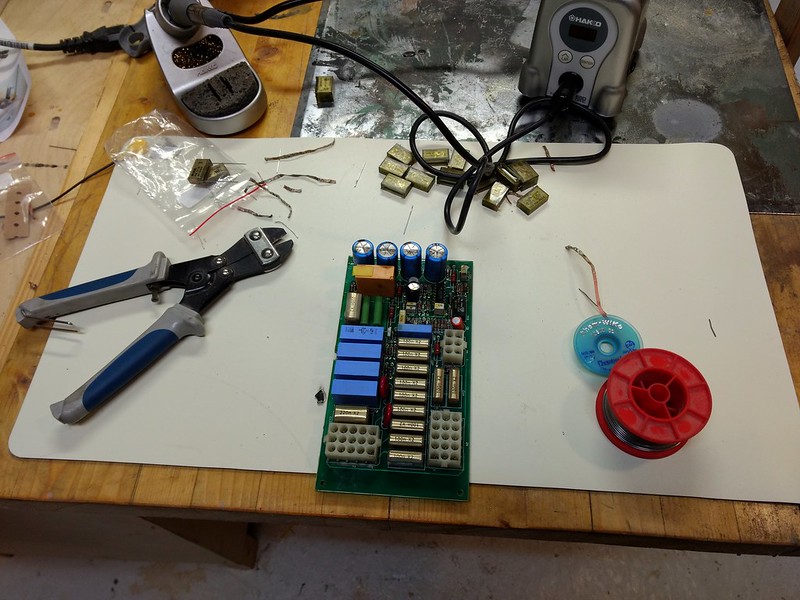 Also what the PSU power supply turned out like, only one ground outlet for now, only had one black. 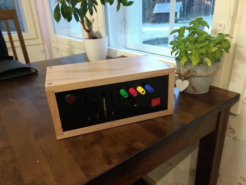 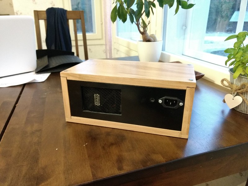 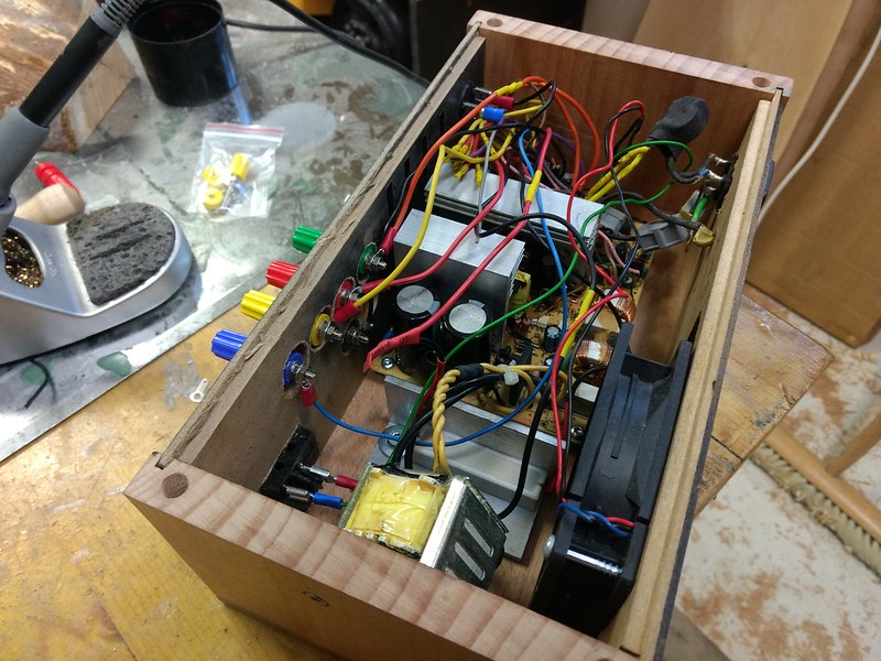 Not entirely happy with the fit of the wooden parts, might redo it in the future, for now it works. I attached the dummy load resistor to a piece of aluminum angle iron with thermal paste.
|
|
#
?
Oct 27, 2018 08:36
|
|

|
99% isopropyl alcohol and a hoghair brush get a lot of forms of soldering crap off of PCBs.
|
|
#
?
Oct 27, 2018 08:42
|
|
|
BattleMaster posted:99% isopropyl alcohol and a hoghair brush get a lot of forms of soldering crap off of PCBs. Don't forget the kimwipes, otherwise you just end up diluting it and spreading it around sometimes.
|
|
#
?
Oct 27, 2018 15:49
|
|


|
I use an old toothbrush Don't use it on your mouth again, though, unless you really need to get all the oxides off your teeth
|
|
#
?
Oct 27, 2018 19:25
|
|

|
I didn't have any isopropyl so I tried denatured. I wouldn't call it a resounding success but better than before. I did the other board which required taking the welder apart some more, but I got it done and back together and I didn't ruin it! Infact the arc is much smoother now, especially at low currents.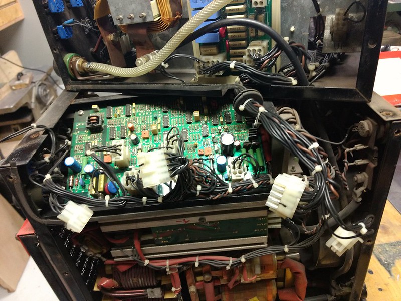
|
|
#
?
Oct 27, 2018 19:55
|
|
|
His Divine Shadow posted:I didn't have any isopropyl so I tried denatured. I wouldn't call it a resounding success but better than before. I did the other board which required taking the welder apart some more, but I got it done and back together and I didn't ruin it! Infact the arc is much smoother now, especially at low currents. For future reference, denatured alcohol can be okay, but it's less standardized than IPA (denatured just means they added toxic stuff to ethanol so you can't drink it), so it might have more water content, or additives that could dissolve plastic parts. If you absolutely must use it, wipe up as much residue as you can, and wait until it's fully dry before applying power.
|
|
#
?
Oct 27, 2018 20:17
|
|
|
Shame Boy posted:An easy thing to verify would be to just pop the lid off and take a look at the circuit board. Make sure none of the capacitors look suspicious (bulged, leaking, etc.) and also look to see if there's any like, gunk on the board. There's some weird silicone-y goop some vendors previously used to glue stuff in place and keep it from vibrating, that after a few years apparently breaks down and becomes conductive. As far as I know the only kind of goop that does this is black colored, so if you see any black gunk use a multimeter to see if it's conductive at all. Thanks, good idea. The caps all look nice, and the only goop I see is some yellowish glue. Notably there are two Big Boi capacitors that are glued in place and I'm afraid of them but I faced my fear and found that the goop is not conductive. The buzz sounds like uh, well it sounds like an old poorly grounded guitar amp, actually. Which is why i checked if grounding the ground screw did anything (it didn't). A new development though, is that now it's not buzzing, but instead the left channel is just extremely weak.
|
|
#
?
Oct 28, 2018 19:37
|
|
|
Anyone ever use... whatever this is? https://www.youtube.com/watch?v=9e7KgF3fWGI
|
|
#
?
Oct 30, 2018 03:41
|
|
|
What's the best cheap multimeter for household stuff right now? I always need one at my parents' house and theirs is a garbage analog thing that's falling apart.
|
|
#
?
Oct 31, 2018 18:53
|
|
|
shovelbum posted:What's the best cheap multimeter for household stuff right now? I always need one at my parents' house and theirs is a garbage analog thing that's falling apart. Whatever meter Harbor Freight runs a coupon for. I wouldn't trust it for most of my projects, but it's useful for seeing if a battery is dead, if a cable is broken, or if your mom was wrong about which breaker cuts power to the smoke alarm you're about to get zapped trying to rewire.
|
|
#
?
Oct 31, 2018 23:12
|
|
|
Just make sure to buy some extra 9-volt batteries too. The cheap meters seem to have a constant slow drain, and if the batteries die they just start giving super weird measurements instead of alerting you and shutting down like an expensive one. Don't expect that the meter you pull out of grandma's hardware drawer will just work. Analog meters are actually much better in that sense, because for voltage and current measurement they're nothing but a calibrated resistor network.
|
|
#
?
Nov 1, 2018 01:57
|
|
|
Really any $20-$40 auto-ranging amazon one is probably fine. In addition to my fancy pro meter I have one of these that works nearly as well for 99% of jobs: https://www.amazon.com/gp/product/B071H8PR61/ That one in particular isn't sold anymore but there's virtually no difference between it and any of the other auto-ranging multimeters in the same price range  e: Apparently Amazon still sells it but it's $70 now and it's not really worth that much
|
|
#
?
Nov 1, 2018 02:13
|
|
|
A lot of the guys I work with swear by Extech meters in general I think also
|
|
#
?
Nov 1, 2018 02:19
|
|
|
Extech probably makes the best cheap meters.
|
|
#
?
Nov 1, 2018 02:47
|
|
|

|
| # ? May 28, 2024 02:46 |
|
|
For the price point, the quality is good, and their catalog selection is wide. I use a 380947 clamp meter for work every day. Not fast, but accurate enough.
|
|
#
?
Nov 1, 2018 03:27
|
|