


|
Nah you can run 500A through 12-mil PCB traces no problem.
|
 #
?
Sep 8, 2016 21:37
#
?
Sep 8, 2016 21:37
|
|

|

|
| # ? May 18, 2024 21:54 |
|
|
rawrr posted:AFAIK that's for steppers; the servos that are usually paired with those boards are just DC motors with step down gears and a potentiometer for position sensing, so when it's not moving it doesn't draw any current. That's why I said "under load" - if you tug on a servo it will detect it's not in the right position and try to correct for it. If you put a constant force it will do that constantly.
|
|
#
?
Sep 8, 2016 22:57
|
|


|
insta posted:Nah you can run 500A through 12-mil PCB traces no problem. thats what I thought 
|
|
#
?
Sep 9, 2016 01:14
|
|

|
ekuNNN posted:Yes, 670 to be exact. They don't have to do any hard work or anything though. I plan to control them by daisy-chaining 42 of these boards: https://www.adafruit.com/products/815 
|
|
#
?
Sep 9, 2016 01:24
|
|

|
I know, project has to be finished end of this month too 
|
|
#
?
Sep 9, 2016 01:31
|
|
|
insta posted:Nah you can run 500A through 12-mil PCB traces no problem. But yeah apart form the sarcasm, should i just wire up every 16 servo board, or like every 5 boards or whatever? Also because, im pretty inexperienced at working with these kinds of loads, can you just connect two power units to power a whole bunch of these board if you hook up the +5v and GND further along the daisychain?
|
|
#
?
Sep 9, 2016 01:39
|
|
|
I have a feeling that the limiting factor on daisy chaining current is going to be the PCB trace, except I don't know how to calculate that. I have a feeling that Adafruit wasn't expecting anyone to want to daisy chain more than a couple of them together, too, so they don't seem to have advice on that. But if you can find out how/find someone who knows how, then figuring out what the limit is should be pretty easy - as long as the current is below the limit minus like a 10% or 20% margin.
|
|
#
?
Sep 9, 2016 02:15
|
|
|
Your worst case load sounds pretty unlikely. If you can model or simulate a typical use case, run 5-10 adafruit boards' worth of servos doing that, measure the peak and average current, scale it up and multiply by 1.5, and you should be okay. Fuse it at 10% less than your supply's max just in case the motors all get jammed. Edit: is there a compelling reason you want to daisy chain power to the extent the traces can handle? Seems pretty unlikely that 670 servos are collocated closely enough that that'd be a cable savings. Just power them in parallel. In the case where you'd want to daisy chain, just jumper from input to input off board. KnifeWrench fucked around with this message at 02:52 on Sep 9, 2016 |
|
#
?
Sep 9, 2016 02:48
|
|


|
Don�t buy Adafruit boards if you�re buying that many. That�s a major waste of money.
|
|
#
?
Sep 9, 2016 03:14
|
|

|
Or do buy Adafruit's boards, because they're reliable and well-documented and fully supported and not everyone is a dirt poor goon whose time is worthless. Furthermore, have you priced out commercial PLCs and servo controllers recently? Adafruit's boards are an incredible deal in comparison.
|
|
#
?
Sep 9, 2016 05:30
|
|


|
rockcity posted:I'm looking to build a set of Christmas lights to replicate the ones from Stranger Things. I did a ton of searching around for addressable lights and most of them would have required a ton of modifying and re-wiring to get them to look how I want them to, but I stumbled across a site selling ones that actually look like Christmas lights rather than just an LED strip light. Sparkfun put up a video of their take on this project. Since budget isn't much of an option for the company that sells stuff they used addressable LEDs wired together and put old school lamps over them as diffusers/covers: https://www.youtube.com/watch?v=ZkAxEGFXsic https://github.com/sparkfun/Stranger_Things_Wall
|
|
#
?
Sep 9, 2016 05:34
|
|


|
KnifeWrench posted:Edit: is there a compelling reason you want to daisy chain power to the extent the traces can handle? Seems pretty unlikely that 670 servos are collocated closely enough that that'd be a cable savings. Just power them in parallel. Yeah, thats what I'm planning. I was just sanity checking cause I'm nervous about powering so many servos together Sagebrush posted:Or do buy Adafruit's boards, because they're reliable and well-documented and fully supported and not everyone is a dirt poor goon whose time is worthless. Yeah, I have the money in this project to buy them, but not the time to figure out getting those boards built myself or to custom design some other board.
|
|
#
?
Sep 9, 2016 11:49
|
|
|
Rexxed posted:Sparkfun put up a video of their take on this project. Since budget isn't much of an option for the company that sells stuff they used addressable LEDs wired together and put old school lamps over them as diffusers/covers: Awesome! That will definitely help me with putting together the code for it, though looking at people's code, it seemed pretty simple to begin with.
|
|
#
?
Sep 9, 2016 13:29
|
|
|
Sarcasm aside, you are far better off with 21 separate 5v/10A supplies. You should be able to find them for $10/ea in quantity on eBay, and they're a lot easier to work with than 500A cables. Run two boards per supply (that still seems like a ton of amperage -- what size servos?), and use regular 16awg stranded PVC insulation wire. For the daisychaining, just use ground and signal between the boards, keep the 5v itself isolated. My gut feeling is you can run 15 separate 5v @ 5A supplies chained 3 ways, and 1-2 10A ones on certain boards.
|
|
#
?
Sep 9, 2016 13:31
|
|
|
insta posted:that still seems like a ton of amperage -- what size servos? I thought so too at first but the stall current of something like a HS-311 is supposedly around 0.6A at 5V so the total theoretical stall current of all 670 of them would be around 400 A, add a 20% safety margin like was described and there's your 500
|
|
#
?
Sep 9, 2016 14:11
|
|
|
Parallel Paraplegic posted:I thought so too at first but the stall current of something like a HS-311 is supposedly around 0.6A at 5V so the total theoretical stall current of all 670 of them would be around 400 A, add a 20% safety margin like was described and there's your 500 500A resistive losses gotta be insane
|
|
#
?
Sep 9, 2016 15:19
|
|

|
A U.S. residential circuit can�t handle it, by the way, if that�s a problem. 400 A � 5 V = 2000 W 120 V � 15 A = 1800 W
|
|
#
?
Sep 9, 2016 15:24
|
|
|
Platystemon posted:A U.S. residential circuit can’t handle it, by the way, if that’s a problem. I can't imagine he's going to plug 670 servos into a single three-pronged wall socket. If you want to see a fire inspector cry, though, build it like that and invite them over to take a look
|
|
#
?
Sep 9, 2016 17:50
|
|
|
ekuNNN posted:Yes, 670 to be exact. They don't have to do any hard work or anything though. I plan to control them by daisy-chaining 42 of these boards: https://www.adafruit.com/products/815
|
|
#
?
Sep 9, 2016 20:18
|
|


|
Platystemon posted:A U.S. residential circuit can�t handle it, by the way, if that�s a problem. I realised before, but I appreciate the warning  Collateral Damage posted:Can I ask what you need 670 servos controlled by a single controller for? We're basically making a screen out of servos. White pixels are servos in one position, Black pixels servos in another position. It doesnt Have to be controlled by a single controller, but the less controllers I have to buy the better.
|
|
#
?
Sep 9, 2016 23:13
|
|
|
ekuNNN posted:I realised before, but I appreciate the warning If it's just two positions for each piece you could use latching solenoids instead, they'd probably be a bit more energy efficient and don't require PWM drivers to control, just a simple on/off signal. What's the "pixel" made of, is it like a flipdot? Because we have way more efficient ways of dealing with flipdots. (In case someone doesn't know what a flipdot is:) https://www.youtube.com/watch?v=Y0r_Q96qiwM
|
|
#
?
Sep 9, 2016 23:44
|
|
|
ekuNNN posted:We're basically making a screen out of servos. White pixels are servos in one position, Black pixels servos in another position. It doesnt Have to be controlled by a single controller, but the less controllers I have to buy the better. e: And if you have to custom build it, as PP said if you're only using two absolute positions anyway, solenoids are going to be a much better solution than servos. Collateral Damage fucked around with this message at 23:55 on Sep 9, 2016 |
|
#
?
Sep 9, 2016 23:47
|
|
|
Parallel Paraplegic posted:I thought so too at first but the stall current of something like a HS-311 is supposedly around 0.6A at 5V so the total theoretical stall current of all 670 of them would be around 400 A, add a 20% safety margin like was described and there's your 500 You don't need to operate in worst case though just protect against it with fuses etc. And realistic operating current can easily be an order of magnitude less in this case. So just measure the current draw of a servo in the planned scenario and go from there.
|
|
#
?
Sep 10, 2016 04:46
|
|

|
Servos let you set each "pixel" to a variety of angles, though, so that could lead to some neat effects. I'm thinking like a gigantic DLP chip. Cover it with mirrors and make an optical phased array to selectively blast squirrels in your backyard with a focused beam of sunlight.
|
|
#
?
Sep 10, 2016 17:47
|
|
|
Does anyone have any resources for teaching soldering? I've been soldering for ages, but I may actually be semi-formally teaching it to a small group at work in the near future and that'd be my first time where it wasn't just an informal one-on-one thing.
|
|
#
?
Sep 10, 2016 19:05
|
|
|
Get one of those video visualizer things that has a zoomable webcam and connects to a projector, so you can show what you're doing blown up on the wall. That's what I do whenever I'm teaching finicky manual skills. Super super useful. At least, that's what I do in classes of ~20 people. If it's a small group at work it may be sufficient to just get a regular webcam and a large monitor. Also, teach in small chunks and give everyone a chance to reinforce that particular lesson by trying it before moving on to the next thing.
|
|
#
?
Sep 10, 2016 20:37
|
|
|
Collateral Damage posted:So like a giant servo driven flip-dot display? How big is each pixel going to be? I'm pretty sure you can get off the shelf flip-dots up to at least a few inches in dot size. Nah, its about puilling floating stuff underwater, and letting it drift back up. solenoids, or at least the stuff i looked at was all too short a distance. I'll show the project here when ts finished beginning of next month
|
|
#
?
Sep 11, 2016 01:16
|
|
|
(crossposted from electronics stackexchange) I have a 1258MHz transmitter running at 1W output power. I want to switch it between two antennas while it's in the field. Can I use a pair of any standard MOSFETs for this, assuming the power dissipation of the FET is adhered to? If not, what do I look for in the datasheet to know that a particular FET is appropriate? If a FET isn't appropriate, what kind of device would be? I'm not oscillating the thing at anything more than 1hz (at worst!), so I don't think I need the special "RF" components.
|
|
#
?
Sep 12, 2016 02:30
|
|
|
Anyone have experience with load‐bearing conductors? I want to put a Nixie tube on the pull handle of a pendulum clock. Parameters are indoors, 2 m long, actual tension maybe 30 N (7 lb), transferring 500 mW at human‐safe voltage (e.g. 20 mA at 24 V DC; I need a HVDC converter on the other end regardless), wound and unwound from a small drum every few days. The cables can�t be too thick or they won�t fit on the drum, and I want it to look good. Load‐bearing copper and current‐bearing stainless steel are both silly things, but at least for stainless steel I think I have a decent idea of how it would behave�high but manageable resistance, good mechanical performance. Copper, on the other hand, isn�t often used for its tensile strength. I am thinking to use small‐diameter plastic‐coated steel rope (I�d call it �cable�, but that doesn�t seem to be the trade name) as one conductor for its tensile strength and slack copper wire (either magnet wire or fine braided wire) for the second conductor, tying hitches around the steel rope regularly to keep them together. If anyone has a better idea, let me know. I did imagine exotic solutions like single‐wire power transfer, LASERs, and induction, but those are probably bad ideas.
|
|
#
?
Sep 13, 2016 14:07
|
|
|
Platystemon posted:Anyone have experience with load‐bearing conductors? Why does the conductor need to carry the load? Can't you just add a chain in parallel?
|
|
#
?
Sep 13, 2016 14:33
|
|
|
KnifeWrench posted:Why does the conductor need to carry the load? Can't you just add a chain in parallel? I�m not going to lie; it�s as much for technical challenge as for practical purposes. I wouldn�t use chain, though. I�d use something like Dyneema fishing line. Allowing that, what would you use for the parallel conductors? Platystemon fucked around with this message at 14:47 on Sep 13, 2016 |
|
#
?
Sep 13, 2016 14:42
|
|
|
Platystemon posted:I�m not going to lie; it�s as much for technical challenge as for practical purposes. Any given insulated cable? If it's not supporting weight it can be literally anything that can take 24V at 0.5A, pick wire that's aesthetically pleasing I guess?
|
|
#
?
Sep 13, 2016 14:49
|
|
|
DIY & Hobbies � The Learning Electronics MEGATHREAD: Use wires.
|
|
#
?
Sep 13, 2016 14:58
|
|
|
Steel will easily transmit that amount of power with nearly zero degradation. Make sure you use a short length of "automation cable" to make the turn onto the pendulum arm. It's designed to flex millions of times in its lifetime.
|
|
#
?
Sep 13, 2016 14:59
|
|
|
Now that�s the sort of advice I was looking for. Thanks. I thought of how pendant lights handled it and how elevators handle it, but not how robots handle it. Platystemon fucked around with this message at 15:16 on Sep 13, 2016 |
|
#
?
Sep 13, 2016 15:12
|
|
|
Do those automation/flex cables have special alloys or just a special weave or something else? I know it is expensive but not much about how it is engineered to be special.
|
|
#
?
Sep 13, 2016 15:32
|
|


|
All the automation cable I've worked with has been somewhat stiff, and specifies a minimum bend radius. You'll probably end up with a teardrop loop (a 270 degree turn) instead of a 90. This will spread the flex out over more of the cable. Neat project ")
|
|
#
?
Sep 13, 2016 15:33
|
|
|
McMaster�Carr has a really good selection of wire. No load‐bearing wires, sadly. Pages 828 and 829 have the good stuff. Long-Life Continuous-Flex Wire, Stranded Carbon Fiber, 38 Gauge sounds interesting. Shame it�s $2∕foot and can�t be soldered to. quote:Carbon fiber wire has 12,000 flexible strands that are nearly invisible on X-rays and imaging equipment. �Long-Life Continuous-Flex Wire, Metallic Tinsel with Kevlar Core, 33 Gauge�, �32 Gauge Miniature Continuous-Flex Wire�, or even �Flexible Miniature High-Temperature Wire, 36 Gauge� ought to work, though. They�re all basically the same price, so I like the sound of the first. Platystemon fucked around with this message at 18:46 on Sep 13, 2016 |
|
#
?
Sep 13, 2016 18:39
|
|
|
So I got this welder with a bum LCD panel. It's a pretty old machine, 1990s era something. I took off the covers tonight to have a closer look at the panel. I'd really like it replaced as its job is to show what amperage I am using.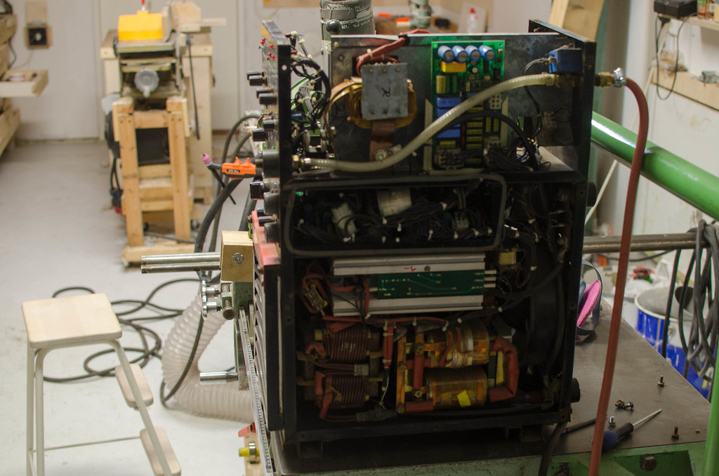 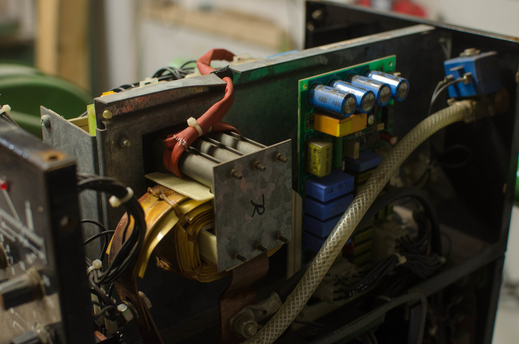 Here's the display itself, mounted on a circuit board. I counted 20 pins on one side, so a 40 pin LCD. Googling that gives me a bunch of results. Would it just be a matter of buying one and swapping it out, a plug and pray operation essentially?  Rest of the machine if anyone cares, it's some kind of early inverter. It was made in Finland during the heyday of the finnish electronics sector which had a real boom in the 90s. 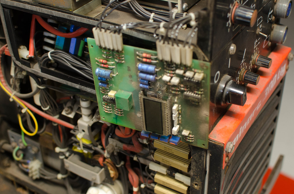 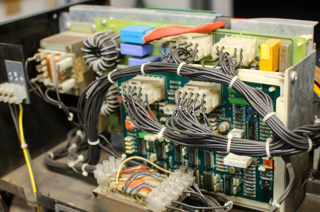 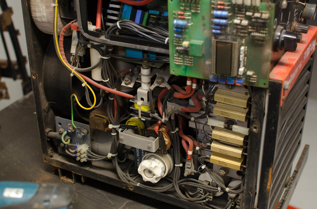
|
|
#
?
Sep 14, 2016 19:46
|
|

|

|
| # ? May 18, 2024 21:54 |
|
|
insta posted:(crossposted from electronics stackexchange) I don't have intimate knowledge of designing these kinds of systems, but have a hunch that what you want may be kind of tricky to design. Even though you may not be switching between antennas quickly, the 1 GHz signal needs to pass through the switch without being attenuated. If you were to buy ordinary high power FETs to do this I'd be shocked if they could respond to GHz signals. Why not just buy an RF switch? Peregrine Semiconductor sells a lot of surface mount RF switches which could do what you are interested in. Various companies also sell RF switches with coaxial connectors, which may be more convenient for you to use. The connectorized switches will be more expensive though, though. silence_kit fucked around with this message at 20:16 on Sep 14, 2016 |
|
#
?
Sep 14, 2016 19:59
|
|
