


|
As a comparison I checked McMaster and found I could download the 3d model of the 4000 lb gantry that they sell... So, uh, might be a good place to start? I imported it into Fusion and found all the dimensions to be there... They are using a 100 X 200 beam, ~7mm web. Exterior beam is 100 mm square, 6mm thickness. Interior square tube is 3.5 inch (88.9mm) to slide into the 100mm square. 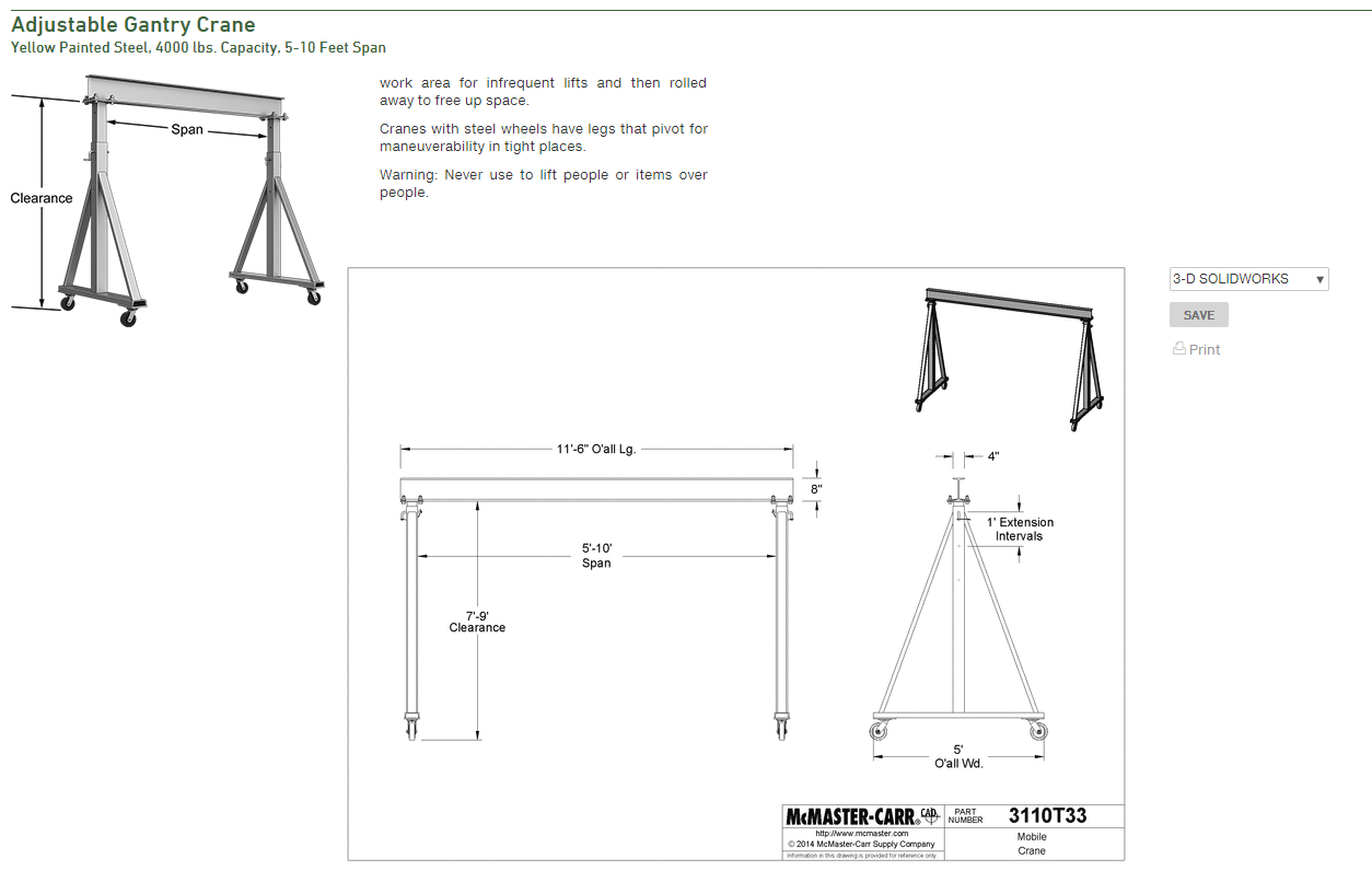
|
 #
?
Dec 1, 2018 03:22
#
?
Dec 1, 2018 03:22
|
|


|

|
| # ? May 10, 2024 13:14 |
|
|
Chillbro Baggins posted:I'd go with ~4"/100mm just to be safe. Yooper posted:Exterior beam is 100 mm square, 6mm thickness. Interior square tube is 3.5 inch (88.9mm) to slide into the 100mm square. 
|
|
#
?
Dec 1, 2018 04:52
|
|
 Bad Angus! Bad!
|
Chillbro Baggins posted:For an example of safety factor, climbing ropes are generally rated to take ~2000lbf/9kN. 10x or so the weight of your average fit person, maybe 3x the actual load if it arrests a fall. This will actually be on castors once it's done, it's so I can pick up my milling machine, lathe etc and move them around.
|
|
#
?
Dec 1, 2018 07:38
|
|

|
Yooper posted:As a comparison I checked McMaster and found I could download the 3d model of the 4000 lb gantry that they sell... So, uh, might be a good place to start? I imported it into Fusion and found all the dimensions to be there... I had been looking for some reference dimensions but had to go by eye. The I-beam I am using is an IPE-140 which is 140x73 and it's only 1700mm long, this design is over 3500 mm. I had help with the selection of the i-beam from engineers. I also showed them this last night so hoping for some input from that source.
|
|
#
?
Dec 1, 2018 07:48
|
|
|
M_Gargantua posted:The bigger worry's I'd have with the design would be an off axis loading that would torque it. That design as is has little lateral strength. And you are putting different size square stock inside each other so the total height can be adjusted? How are you going to lock it in place? How are you going to anchor it to the floor? It would be pretty useless locked to the floor, it's going to be mobile, it will lift whole machines an inch or so off the ground so I can move them, tables and other heavy parts that are just too heavy for me to lift comfortably would be the second thing I am using it for, none of that would top over 200kg max I think. My heaviest machine is 1200kg but I think I should dimension it to the hoist capacity of 1600kg. Lateral = sideways racking? So make the upper diagonals longer? The uprights would be locked using a bolt of some kind through the holes, a replica of a commerical solution at any rate. EDIT: I am looking real hard at bigger profiles but it's a real pain in the rear end, these two profiles with the wall thickness of the bigger one resulted in a fit with a millimeter of play in either direction. That's probably precisely what is needed. Haven't found another combination that yields the same, square pipes come in increments of 10, i.e. 70, 80, 90, 100. So I could get a 100x100x5mm square tube and a 90x90x5mm tube, but that would have no slop at all so it most likely would not fit, these things tend to have seams on the inside too. His Divine Shadow fucked around with this message at 08:14 on Dec 1, 2018 |
|
#
?
Dec 1, 2018 07:55
|
|
|
If you're loading 1200kg I'd definitely design for about 4800 or so if it's minimal load movement. Maybe some locking tags for snatch straps or similar so you can lock it in place so it doesn't swing sideways too much if you're lifting the lathe
|
|
#
?
Dec 1, 2018 08:19
|
|


|
Buckling mode simulation in Fusion 360 for 4x the load, doesn't look good... But oh yeah the load I put in was 4.8 tons so that's a load of 19 tons   This is with the bigger sized uprights, 100x100x4mm and 90x90x4mm, this is another size combo that fits into the sizes that you can find over here. I am not 100% on the fusion and the structural constraints, ideally they should both be able to move in X and Y axises but that makes the simulation fail, so I locked the bottom of one leg and left the other free. I also made the bottom diagonals longer, 15 degree inclination instead of 45 so they connect higher up. Same simulation using 1600kg of force or 15690 newtons looks pretty much the same but that load is 11.9 times the stated one, so again around 19 tons. I wish I knew how to make fusion stop adding on and show me visually what happens at exactly the load I put in instead of continuing on to various failure modes.
|
|
#
?
Dec 1, 2018 09:19
|
|
|
His Divine Shadow posted:Buckling mode simulation in Fusion 360 for 4x the load, doesn't look good... But oh yeah the load I put in was 4.8 tons so that's a load of 19 tons You can change the display from safety factor to displacement (or stress, or a bunch of other mech.eng non-sense).
|
|
#
?
Dec 1, 2018 12:28
|
|
|
His Divine Shadow posted:It would be pretty useless locked to the floor, it's going to be mobile, it will lift whole machines an inch or so off the ground so I can move them, tables and other heavy parts that are just too heavy for me to lift comfortably would be the second thing I am using it for, none of that would top over 200kg max I think. My heaviest machine is 1200kg but I think I should dimension it to the hoist capacity of 1600kg. To get square tube to slide easily within other square tube will require rework or exceptional luck. I don't think they'll be perfect enough from the supplier to slot together directly. Lateral X would be the verticals wanting to splay outward at the base as you add weight up top, Lateral Y would be the whole thing wanting to tip over if whatever youre holding sways front to back. Your design as is will probably snap at the base if you don't triangluate it against front to back motion like the McFaster example. e; This sim looks very much like a widely distributed force rather than a small area force.
|
|
#
?
Dec 2, 2018 03:12
|
|


|
So just to show what I mean this is a 6ft S6x17.25 A36 beam with a 1800kg load spread over a 4" area around the center. (200:1 deformation exaggeration) This is just the beam alone. I'm going to end up doing a more comprehensive model now that I'm into it. This reported a 2.9 FOS.  And this is the profile of where the weight is distributed (mirrored onto the other side too). If I knew the dimensions of the dolly I could spread it out further but in smaller contact points to simulate rollers. 
|
|
#
?
Dec 2, 2018 03:25
|
|
|
Don't worry about a perfect nest between the tubes. You're probably going to adjust this one side at a time and it would be pretty annoying if they were tight. I would consider putting the small tube on the bottom so there's a lot of big tube to use as a handle and you wouldn't get pinched when lowering.
|
|
#
?
Dec 2, 2018 05:43
|
|
|
To be honest I am wondering if it's worth all the effort, the material costs alone are going to be so high I am realizing. I am considering just buying a 2 ton shop crane / engine hoist.
|
|
#
?
Dec 2, 2018 07:32
|
|
|
M_Gargantua posted:To get square tube to slide easily within other square tube will require rework or exceptional luck. I don't think they'll be perfect enough from the supplier to slot together directly. I honestly don't see where their design is different from what I made in regards to that. I assume you're talking about the A frame style feet at the bottom, do you just mean they should be longer? Both designs seem to be about the same, perhaps theirs are wider at the bottom and the diagonals go farther up for better stability. OTOH they have no diagonal bracing at all on the top like I do. Here was the latest image with bigger verticals:  edit: And here I made the bottom A frame even wider and increased the diagonals, tbh my version is looking beefier than the mcmaster one now, with the exception of the i-beam. But I might be wasting my time on this since I am no longer sure I ought to be making one.... 
His Divine Shadow fucked around with this message at 07:55 on Dec 2, 2018 |
|
#
?
Dec 2, 2018 07:37
|
|
|
Still working in fustion and I think I got the simulation to work properly when I swapped to a static load stress instead of a buckling simulation. Responded with more info than it ever did before: The width of the legs are now 1.4 meters. But I realize this is too wide for my shop, 1.2 meters max is what I can get away with. I am thinking perhaps I can and make a bigger a-frame, which should be a more stable design, perhaps allow me to get by with smaller stock size and no need to worry about profiles fitting into each other.
|
|
#
?
Dec 2, 2018 11:07
|
|
|
Divine, what sort of floor do you have in your shop?I use a lever and some (homemade and overbuilt) skates to move around smaller machines (hardinge, XLO, harig, crystal lake).
|
|
#
?
Dec 3, 2018 03:39
|
|


|
I've had that suggestion before but people don't know my requirements fully when they recommend that. It's not just moving machines around and getting them on and off pallets. This mill (1300kg) in order to continue disassembling it and repair the galling damage on the x-axis dovetail I will need a crane to lift the table. The same goes for the milling head and sliding top parts which I also need to get out for cleaning and inspection, and just in general usage of this machine a crane will be needed to remove and add parts. My floor is concrete for what its worth. And after further discussion with local machinists last night I have decided to give up the gantry crane idea and get myself a HF style 2-ton crane that I can modify and beef up.
|
|
#
?
Dec 3, 2018 05:31
|
|
|
Any recommendations for 4 1/2� angle grinders? I�m looking at stuff under $100 and in the 7-10 amp range.
|
|
#
?
Dec 3, 2018 15:49
|
|

|
rump buttman posted:Divine, what sort of floor do you have in your shop?I use a lever and some (homemade and overbuilt) skates to move around smaller machines (hardinge, XLO, harig, crystal lake). What do you think of your Crystal Lake grinder? Is it the belt over top unit?
|
|
#
?
Dec 3, 2018 16:00
|
|
|
I haven't used it much, we got it in the 80s, and have sparsley used it in our custom mold shop. The thing is very stout, a real machine tool. We just don't have that much of use for it. It's belt driven.  We joke about a few of our machines being more towards museum pieces than tools we use. We've also got a Hauser jig bore from the 4o's and a deckel pantograph. The Hauser is 8500 lbs and still holds insane tolerances. The deckel is pretty cool, but very tiring to use. We don't really use any of the three machines anymore but that are all pretty dope in the overbuilt machines of yore kinda way. rump buttman fucked around with this message at 02:34 on Dec 4, 2018 |
|
#
?
Dec 3, 2018 17:41
|
|
|
coathat posted:Any recommendations for 4 1/2� angle grinders? I�m looking at stuff under $100 and in the 7-10 amp range. Maketa is the go to for grinders.
|
|
#
?
Dec 4, 2018 06:00
|
|

|
coathat posted:Any recommendations for 4 1/2� angle grinders? I�m looking at stuff under $100 and in the 7-10 amp range. The grinder quality is negotiable; abrasive quality isn't. Given $100 I'd buy the Harbor Freight special and name-brand wheels instead of the inverse. Of course, that wasn't actually your question; you can def get a decent Makita, Bosch or Milwaukee for that budget, and they'll all serve well. If you can buy it from somewhere with a good return policy, I'd feel much less reluctant to cheap out; up in Canada we have Princess Auto for our garbage-tier power tools, but unlike HF their return policy is no-questions-asked full-refund as long as they still carry the thing and it's in the system, so reliability isn't a big concern when you know you can get the sticker price back if needed.
|
|
#
?
Dec 4, 2018 07:22
|
|

|
Ambrose Burnside posted:The grinder quality is negotiable; abrasive quality isn't. Given $100 I'd buy the Harbor Freight special and name-brand wheels instead of the inverse. FWIW I bought a PA grinder yeaaaaarrs ago, it chucked a ball bearing out of its' gearbox (yes, like right through the cast housing) and kept on wire wheelin' for 6+ months before I retired it. They're not built great but they take a beating really well. And cheap. That said I would buy a good makita, milwaukee, or one of the heavy duty hitachi (the green ones) any day.
|
|
#
?
Dec 4, 2018 07:37
|
|


|
We have makita grinders at school and they cop an absolute beating off a bunch of high school kids day in day out without issue. Our Milwaukee cordless drills on the other hand are a pile of poo poo. On the newest ones we have the drill stops working even with a brand new battery. The only way to fix it is to pull the battery out then put it back in again.
|
|
#
?
Dec 4, 2018 10:59
|
|
|
rump buttman posted:I haven't used it much, we got it in the 80s, and have sparsley used it in our custom mold shop. The thing is very stout, a real machine tool. We just don't have that much of use for it. It's belt driven. We've got some folks here that wax nostlagic about them. To me everything looks pretty light duty. I wonder if the nostalgia is just because your standard OD grinders weren't as nice back then. I think a modern Studer or Weldon would grind circles around one of those. Also OSHA lol. Anyone got a good source for a high quality work spindle? I'm in need of an upgrade and I'd like to buy one instead of designing another one.
|
|
#
?
Dec 4, 2018 14:58
|
|
|
The crystal lake design, osha be damned, is a great design for dead nuts grinding. Belts really let the thing purr. Compared to modern machines, it's gonna suck big time. Infinitely so in the jobshop and production side of machining. For toolrooms? They are pretty handy. It's came in handy for us in the past when we've had to make custom cores that needed to be dead nuts or when we have core/pins that are to long to OD with a spin fixture attached to a tool pate on our surface grinder. As far as its duty, it's all relative. Our specialty is plastic injection molds that can fit between 14 inch tie-bars and under 500lbs fully assembled. Most of the delicate parts are under 20lbs. It's pretty loving built for what we do.  1" standard for scale
|
|
#
?
Dec 4, 2018 17:04
|
|
|
A friend needs a part made for on old chandelier and asked me about it. I�ve had some odd bits of furniture hardware cast once before but it was very expensive and I was thinking of giving this a shot myself. I used to do some welding/blacksmithing and have an old coal/charcoal forge and the parts to put together a propane forge with a Ron Reil style propane burner. I figured I�d do lost wax, but don�t really know much about the details of the process except a generally understanding of how it works. Will a propane forge get hot enough to melt brass? Where do you get brass to melt? What kind of a crucible do I need? Am I going to blow myself up? Any books/websites I should investigate? The part in question: https://imgur.com/a/VDHzjar It�s a pretty simple part and it might be easier to have it milled out of solid stock, but I�m still interested in the casting process generally-I can see lots of possibilities.
|
|
#
?
Dec 11, 2018 20:10
|
|

|
Kaiser Schnitzel posted:A friend needs a part made for on old chandelier and asked me about it. I’ve had some odd bits of furniture hardware cast once before but it was very expensive and I was thinking of giving this a shot myself. I used to do some welding/blacksmithing and have an old coal/charcoal forge and the parts to put together a propane forge with a Ron Reil style propane burner. I figured I’d do lost wax, but don’t really know much about the details of the process except a generally understanding of how it works. Will a propane forge get hot enough to melt brass? Where do you get brass to melt? What kind of a crucible do I need? Am I going to blow myself up? Any books/websites I should investigate? It would be not only safer but probably faster to hacksaw and hand-file that from a piece of flat and a piece of square stock, then braze them together. Brass is soft, it'll go a whole lot faster than you think.
|
|
#
?
Dec 11, 2018 20:19
|
|

|
Been under with a bad cold for a while now... Starting to feel a little better. Got myself a 2 ton shop crane and assembled it last night, it seems it will reach where it needs to, in the 1500kg configuration here and there is still a little more height to go on the hydraulic and that chain will be cut as short as I can possibly get it. But the extended support feet won't fit around or under the pallet. The crane is built mainly from 70x70x3mm square tubing. I will be buying some of that and welding a central support post between the rear of the base and the main beam, those metal bands... I don't give much for whatever support they are supposed add.... And I will weld more square tubing at a 90 degree angle on the sides of the base to build new mount points for the extended feet. That will create a space of 85cm between the feet, so a euro-pallet will fit with a little margin. Think that will be perfect. And some extra structure to stiffen everything up. Hard to explain what I mean but I got a mental image of it all... Think it will turn out pretty good. 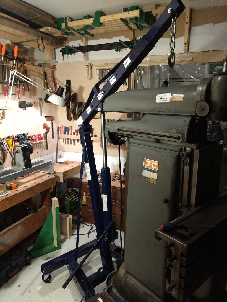
|
|
#
?
Dec 14, 2018 08:16
|
|
|
His Divine Shadow posted:Got myself a 2 ton shop crane and assembled it last night, Funny, I've got that exact same crane and used it to assemble my own lathe+mill. And I also had to modify it to make the feet wider. (did it in a lovely and dangerous way, no pix) The wheels on my crane were out of round by a mm or so, enough that once I had several hundred kgs in the air it became almost impossible to move. Had to turn them down. I've still got mine and have used it a lot but I don't really think you should come too close to the load margins.
|
|
#
?
Dec 14, 2018 17:31
|
|

|
I've read the crane isn't really meant to be moved when handling such heavy loads, so my plan is to build my own machine skates and just use those when moving something in that weight range. Also got some nebulous ideas of beefing up the crane as well to add margins.
|
|
#
?
Dec 14, 2018 18:53
|
|
|
will the machines always be on pallets, because if so, maybe a pallet jack instead of a crane?
|
|
#
?
Dec 14, 2018 19:04
|
|

|
His Divine Shadow posted:my plan is to build my own machine skates and just use those when moving something in that weight range. Also got some nebulous ideas of beefing up the crane as well to add margins. See if you can find some gondola skates cheap. We in the grocery-store-rearranging biz us 'em at four-foot intervals to move the aisles (gondola shelving) around. I was present for one store where they turned all the aisles 90 degrees, while the shelves were fully loaded. That was fun. (And by fun I mean all-hands-on-deck absolute panic to keep them from tipping.) Still kinda hoping for one of my client's competitors to go under so I can score some fire-sale gondola shelving to outfit my shop, though it's not THAT expensive on the regular secondhand market. Random Google result 4' with three uppers for $120, additional shelves  per, but shipping probably expensive. per, but shipping probably expensive.Of the two 800-pound gorillas, I prefer Madix over Lozier, but you can (mostly) mix and match, they're standardized these days (the uprights don't play well together, but both types of shelf fit in a pair of uprights from both brands). As opposed to some stores I've redone that hadn't been touched since Johnson was president ... the second Johnson, at least. There was some weird poo poo before Madix and Lozier took over and made shelves that fit each other's uprights. Edit: if you outfit your shop with grocery-store shelves, be sure you get that poo poo absolutely loving dead-nuts square -- one of my accounts is a warehouse-type store, where they have pallet racks above the gondolas, and bump the shelf bases with the forklifts ... the "shelf stretcher" is our version of "go fetch a bucket of prop wash", but I actually have one -- a 3-pound drilling hammer. My coworkers all carry rubber mallets or light-duty claw hammers, for the ol' tappy-tap-tap, I've been apprenticing in this job (going to work with Mom on summer vacation) since I was 12, getting paid taxable income for it for 8 years, I know all the tricks (most of the tricks involve either a big fuckoff hammer or a metal-cutting saw, maybe the occasional screwdriver-as-cold-chisel). I can force a 48" shelf into a 47.5" space if I have to. I also keep a cordless angle grinder, drill, recip saw, and circular saw (Mom and I are the only two on our crew who can grok pegboard, and sometimes the other crew who do pegboard aren't there to cut it for us) with the biggest available battery in the car, in case there's an inconveniently-placed roof-support post (as do a couple of my client's more knowledgeable showrunners -- the ones that got to management by working their way up from the trenches, stocking and/or rearranging the shelves, as opposed to the college boys that have always been management.) We cut the shelves, not the column, of course. And then jury-rig something to hold up the floppy back of the shelf, having a foot-wide gap in its reinforcing ribs. Although I and the maverick bosses have only-half-jokingly talked about cutting the column when it's in a really annoying spot. Chillbro Baggins fucked around with this message at 04:57 on Dec 15, 2018 |
|
#
?
Dec 15, 2018 03:50
|
|
|
Leperflesh posted:will the machines always be on pallets, because if so, maybe a pallet jack instead of a crane? Definitely not, I want it down from the damned thing just for keeping on working on it.
|
|
#
?
Dec 15, 2018 07:10
|
|
|
Started on the modification of the crane. It had to come apart again for this. Here I have two 70x70x4mm pieces cut to length, these will be welded on where they sit now.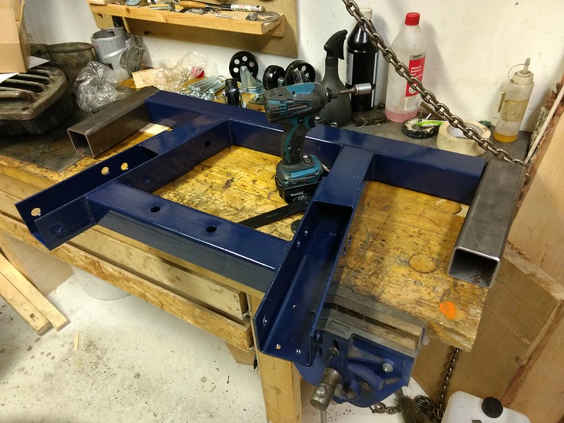 Then similar U-profiles will be welded on to these new pieces, in the same fasion that the angled supports are now made. Then I will cut two shorter bits of the same square profile and weld them between the angled and straight U-profiles. You can see there is a cross-member between the two angled U-profiles in the photo, to which the main post and crane is attached later. I will weld the new cross-members along the same line to stiffen up the base frame. Problem, don't ghot any U-profile and couldn't find any suitable so I plan to make my own from these 6mm plate steel (1/4") 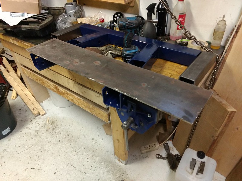 And and cut the pieces to size. I will get 6 pieces of 315x80mm plates out of this. 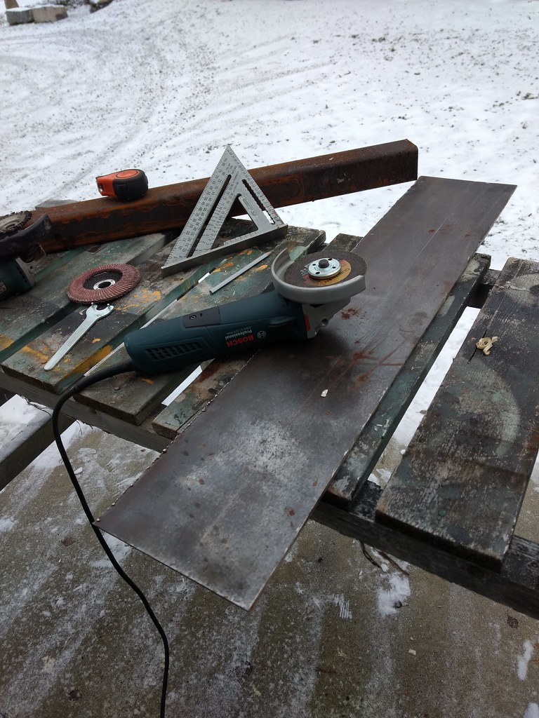 Not the easiest thing to cut straight with the angle grinder. 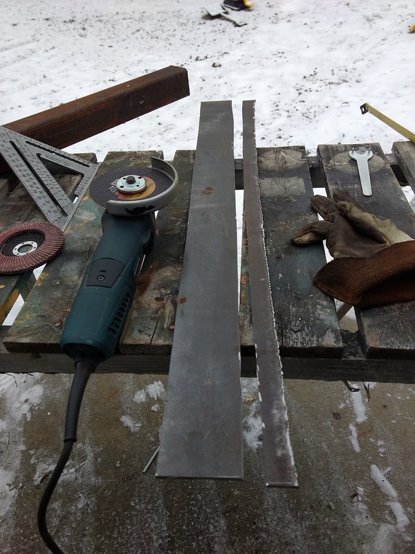 Rough mockup of how I imagine it, will add some sheet metal for shims when I do the actual welding.  Unsure if I ought to TIG or stick weld this. I think stick is probably easier, 7018 is practically made for this kind of work, but I can TIG indoors were it's warm. It's 2PM here and the sunlight is fading. EDIT: Actually, I might need to reconsider how I strengthen up the frame, might need to make a "lid" on the inner u-profiles anyway or that might be a structural weak point. I don't think that will matter that much since I think the legs would be almost permanently installed in the outer supports. His Divine Shadow fucked around with this message at 16:20 on Dec 16, 2018 |
|
#
?
Dec 16, 2018 13:04
|
|
|
His Divine Shadow posted:Started on the modification of the crane. It had to come apart again for this. Here I have two 70x70x4mm pieces cut to length, these will be welded on where they sit now. Tbh stick is probably gonna be way better for this application but I'm no professional
|
|
#
?
Dec 16, 2018 23:46
|
|
|
Yeah I stick welded one profile last night, started with the TIG but no this was too small and too slow. 1/8 rods made pretty quick work of it. Left it clamped up so it could cool in place, Sometimes I wonder if I would be better served with a MIG than a stick/tig combo after all, but I think it's just because I don't practice enough with either TIG or stick so I am always rusty and having a difficult time of it. They do have their pros after all, TIG allows me to work on really tiny things and it is clean, stick allows me to weld outside in any weather and to weld heavy stuff, wind only helps blow away the smoke. Sometimes though you watch videos of people mig welding and it's just like a metal hot glue gun. Looks super easy and gets nice results. But I bet I would want a TIG/stick if I had a MIG welder. So practice practice practice! His Divine Shadow fucked around with this message at 08:11 on Dec 17, 2018 |
|
#
?
Dec 17, 2018 05:22
|
|
|
I've never used a stick welder tbh. I learnt mig first and once you get a hang of the settings it's literally a hot glue gun for metal. I learnt tig later and it owns but I won't do anything except mild steel and heavy stainless with it. Most of what I'm welding is home brewery related anyway so it's all thin wall 316 gear and gets the tig treatment
|
|
#
?
Dec 17, 2018 12:45
|
|
|
I actually quite enjoy stick welding when I get into the swing of it, and no gas required. Gas is such a loving expense here. Paid 90 euros last time I swapped in my TIG bottle (80-85cf size I think), mig gas is slightly cheaper. And this welder has 300 amps capacity so I can weld some heavy poo poo if I want to.
|
|
#
?
Dec 17, 2018 14:46
|
|
|
I don't know how often flux core is used in Suomi but we're starting to use it more often in our shop for jobs where we don't want to lug the big welder out. Given the limited use we don't mind it.
|
|
#
?
Dec 17, 2018 15:33
|
|
|

|
| # ? May 10, 2024 13:14 |
|
|
managed to pitch my bosses on prototyping a custom hook design for a client with The Ancient Arts and it turned out p well for a shop that just waterjets everything had to make the tooling from scratch but that's part of the fuuuun first up, a (small) universal stock bender + dies and adjustable bending bar. most work done on the waterjet, it's pretty easy to undersize the dowel holes and then ream them to spec afterwards    here's the actual hook, bent around a custom profile tool (also waterjetted). the inside of the profile is cut out so i can get the bending bar in there for leverage. also note the cutouts to accomodate the shackle being in place during fabrication; everything was a pretty tight fit but it worked out ok  almost done, just needs a sandblasting and a circlip groove cut higher up (im really stupid for not doing this pre-forging but whatever). the tubing on the hook near the bottom is actually polyurethane, it's there to act as a bumper to accomodate a range of [suspended things] 
|
|
#
?
Dec 17, 2018 17:28
|
|